ÉTUDE DU RELAIS FULL-DUPLEX DANS LES
ENVIRONNEMENTS INTÉRIEURS
STUDY OF FULL-DUPLEX RELA Y IN INDOOR ENVIRONMENTS
MÉMOIRE PRÉSENTÉ
COMME EXIGENCE PARTIELLE DE LA MAÎTRISE EN INGÉNIERIE
PAR
KAZI MUST AFIZUR RAHMAN
Mise en garde
La bibliothèque du Cégep de l’Témiscamingue et de l’Université du Québec en Abitibi-Témiscamingue a obtenu l’autorisation de l’auteur de ce document afin de diffuser, dans un but non lucratif, une copie de son œuvre dans Depositum, site d’archives numériques, gratuit et accessible à tous.
L’auteur conserve néanmoins ses droits de propriété intellectuelle, dont son droit d’auteur, sur cette œuvre. Il est donc interdit de reproduire ou de publier en totalité ou en partie ce document sans l’autorisation de l’auteur.
Warning
The library of the Cégep de l’Témiscamingue and the Université du Québec en Abitibi-Témiscamingue obtained the permission of the author to use a copy of this document for non-profit purposes in order to put it in the open archives Depositum, which is free and accessible to all.
The author retains ownership of the copyright on this document. Neither the whole document, nor substantial extracts from it, may be printed or otherwise reproduced without the author's permission.
DEDICATION
This work is dedicated to my family, Research director, friends, thesis committee, and the staff of the Université du Québec en Abitibi-Témiscamingue (UQAT), School of Engineering. The endless support I have received from ali parties allowed me to complete this and without their help, I'd have given up long ago.
ACKNOWLEDGEMENT
First of ali, I would like to thank my research director Professor Dr. Nadir Hakem, for giving me the opportunity to pursue my graduate studies at the Université du Québec en Abitibi-Témiscamingue (UQAT), and for his support and guidance throughout this journey. Not only have I benefited from his deep knowledge in and outside of the laboratory, but I have also learned a great deal from his way of doing research that will surely help in my career. This thesis would not have been possible without his continuons trust, patience, and encouragement. Furthermore, I would like to express my gratitude to him for always challenging me and providing feedback on my work and for being accessible so I could learn from his extensive knowledge and experience in the areas of wireless research.
I wish to express my appreciation to the members of Masters superv1sory committee, Professor Dr. N ahi Kandi!, Professor Dr. Ismail Ben Mabrouk, for taking the time out oftheir busy schedule to review my reports and attend the seminar.
Also, I gratefully acknowledge the financial support provided by UQAT-LRTCS through the UQAT École d'ingénierie Award. Without such generosity, I would not have been able to concentrate full y on my master's studies.
I am thankful to my friends and colleagues (past and present) of the Laboratoire de Recherches Télébec en communications Souterraines (LRTCS). In
particular, I thank Abdennour Ben Terki for his endless support and French translation. Finally, I would like to express my endless gratitude to my family. My parents instilled a passion for science in me when I was still young. They spare no effort to support me studying abroad. Without their love and support, I would never have been able to study at UQAT.
TABLE OF CONTENTS Acknowledgement ... ... iv L . tst oJ .rF· tg ures ... ... vm ... List of Abbreviations ... ... x Abstract ... ... 1 Résumé ... 2 Œ~1 ... 3 Introduction ... 3 1.1. Research Problematic ... 4
1.2. SI Cancellation Techniques: A Reviw ... 5
1.3. Contribution of Thesis ... 6 1.3. Structure of Thesis ... 7 Œ~2 ... 8 Wireless Communication ... 8 2.1. Introduction ... 8 2.2. Channel Impairments ... 9 2.2.1. Path Loss ... 9
2.2.2. Free Space Path Loss ... 1 0 2.2.3. Shadow Fading Mode!.. ... .... 11
2.2.4. Multipath Propagation ... ... 11
2.2.4.1. Reflection ... .. 12
2.2.4.2. Diffraction ... .. 12
2.2.4.3. Scattering ... ... 13
2.2.5.1. Fast Fading ... . 13
2.2.5.2. Slow Fading ... .... 13
2.2.6. Multipath Fading ... . 14
2.2.6.1. Flat Fading ... .. 14
2.2.6.2. Frequency Selective Fading ... . 14
2.3. Inter-Symbol Interference ... ... 14
2.4. Channel State Information (CSI) ... ... 15
2.5. CCI and Feedback ... ... 15
2.6. Communication Channel.. ... ... 16
2.6.1. Additive White Gaussian (AWGN) Noise ... .. 16
2. 7. Stationary Channel Model ... . 17
2.7.1. Rayleigh Fading Channel Madel.. ... . 17
2.7.2. Rician Fading Channel Madel.. ... .. 17
2.7.3 .. Nakagami-m Fading channel Madel.. ... .... 18
2.8. MIMO Communication System ... ... 18
2.9. Signal Encoding Technique ... ... 20
2.9.1. BPSK Modulation ... 20 2.9.2. QPSK Modulation ... 21 Chapter 3 ... . 23 Cooperative Communications ... 23 3.1. Introduction ... 23 3.2. Relay Function ... . 24
3.21. Amplify and Forward (AAF) ... 24
3.2.2. Decode and Forward (DAF) ... 26
3.2.3. Compressed andForward (CAF) ... 27
3.3. Half-Duplex Relay ... 27
3.4. Full-Duplex Relay ... 29
3.6. MIMO Relaying ... ... 31
Chapter 4 ... 33
Proposed FD-MIMO Relay ... ... 33
4.1. Introduction ... .33
4.2. The Relay System Model. ... 34
4.3. Proposed Two Stage Projection Approach ... .... 35
4.3.1. Projection ... .. .35
4.3.2. Nul! Space Projection (NSP) ... ... 35
4.3.3. Subspace Projection (SP) ... .36
4.3.4. Flat Channel Case ... 36
4.3.5. Selective Frequency Channel Case ... 38
4.3.6. Nul! Space projection (NSP) with short rank loop interference matrix ... .. 39
4.3.7. Subspace Projection Partly Cancelling Interference (SSPCI) with Full Rank (FR) Matrix ... ... 40
Chapter 5 ... 42
Results and Ana/y sis ... 42
5.1. Bit Error Rate (BER) ... ... .42
5.2. Signal-to-N oise Ratio (SNR) ... 42
5.3. BER perfonuance with BPSK Modulation ... 43
5.4. BER perfonuancewith QPSK Modulation ... ... 46
5.5. Result Analysis ... ... 50 Œ~6 ...
n
Conclusion andFuturework ... ... .... 51 6.1. Conclusion ... 51 6.2. Future W ork ... 52 References ... 53LIST OF FIGURES
Figure 2.1: Illustration of reflection, refraction, scattering, and diffraction of a radio
wave ... 12
Figure 2.2: ISI in Digital Transmission ... .. 15
Figure 2.3: The Additive Noise Channel. ... ... 16
Figure 2.4: MIMO Communication System. ... . 19
Figure 2.5: Signal Constellation Diagram for BPSK ... .. 20
Figure 2.6: Signal Constellation Diagram for QPSK ... .. 21
Figure 3.1: Dual-Hop Re lay Communication ... .. 24
Figure 3.2: Amplify and Forward Relaying System ... .. 25
Figure 3.3: Decode and Forward Relaying System ... ... 26
Figure 3.4: HD Re lay Protocols ... .. 28
Figure 3.5: FD Relay Protocols ... . 30
Figure 3.6: MIMO Cooperative Communication System ... . 32
Figure 4.1: Two-Hop Re lay Mode!. ... .34
Figure 4.5: Relay Loopback Interference Signal Cancellation by Using TSPA Scheme ... ... .37
Figure 5.1: BER vs SNR for flat channel with BPSK Modulation ... .43
Figure 5.2: BER vs SNR for Selective Frequency Channel with BPSK Modulation ... .. 44
Figure 5.3: BER vs SNR for High Selective Frequency Channel with BPSK Modulation ... .45
Figure 5.4: Compare to ZF, MMSE and Proposed TSPA with BPSK Modulation .. .46
Figure 5.5: BER vs SNR for flat channel with QPSK Modulation ... . .47 Figure 5.6: BER vs SNR for Selective Frequency Channel with QPSK
Modulation ... .... 48
Figure 5.7: BER vs SNR for High Selective Frequency Channel with QPSK Modulation ... .48
3GPP AF AWGN BER BF BPSK CCI CR CSI D dB DF
DH
FD FRHD
LI LTE LTE-A LOS MMSE MIMO NLOS NSP OLOS QPSK R LIST OF ABBREVIATIONSThird Generation Partnership Proj ect Amplify-and-forward
Additive white Gaussian noise Bit error rate
Beamforming
Binary phase-shift keying Co-Channel Interference
Cognitive Radio
Channel state information Destination Decibels Decode-and-forward Dual-hop Full-duplex Full-rank Ralf-duplex Loopback Interference Long Term Evaluation
Long Term Evaluation-Advance Line of Sight
Minimum Mean Square Error Multiple-input multiple-output
Non-Line of Sight Null Space Projection
Obstructed Line Of Sight Quadrature phase-shift keying Relay
s
SourceSPA
Space Projection AlgorithmSP
Subspace ProjectionTSPA
Two Stage Projection AlgorithmSI
Self-InterrerenceSNR
Signal-to-noise ratioWSN
Wireless Sensor NetworkExpanding the coverage of network with different techniques is necessity and demand oftoday's !ife. As the population increases, the demand for more solutions to give more capacity and to reach everyone on the whole world with network also increases. Recent studies have confirmed that interferences, such as co-channel interferences (CCis) and self-interferences (Sis), have an enormous impact on wireless communication systems and can cause significant performance degradation. Relaying techniques, in which an origin node communicates to the destination node with the help of intermediate node, have been introduced as a cost-effective solution to address the ever growing need for high data rates and available services over the air. As such, it is crucial to design relay systems that can not on! y provide high spectral efficiency but also full y take advantage of the relay channel diversity.
With this objective in mind, this thesis investigates the SI's and CCI's cancellation techniques for Full-Duplex (FD) Amplify-and-Forward (AF) relay equipped Multiple-Input-Multiple-Output (MIMO) antenna system.
This thesis is concerned to develop an efficient SI cancellation algorithm for MIMO relays in the indoor wireless communication system. Transmit and receive simultaneously the same radio signal create an SI around the relay transceivers due to the loop-back signais. The main challenge of implementing FD-MIMO relay is to mitigate the performance deterioration induce or involve by the SI. This work presents an efficient algorithm for mitigating this SI by using Two Stage Projection Algorithm (TSPA) which consists oftwo steps called Null Space Projection (NSP) and Subspace Projection (SP) to reduce or cancel the SI. Simulation results show that the SI of the proposed method is efficient! y minimize.
RÉSUMÉ
Élargir la couverture des services du réseau aux endroits difficiles et aux régions éloignées est un besoin de plus en plus nécessaire de nos vies quotidiennes actuelles et futures. L'augmentation de la population et la demande accrue de services et de solutions de communication requièrent l'augmentation de la capacité des moyens de communication tout en permettant une couverture plus efficiente et plus étendue des territoires et régions faiblement peuplées dans le Canada et dans monde. Des études récentes ont confirmé que des interférences comme les interférences dans le même canal (ICC) et les interférences mutuelles (SI) ont un impact énorme sur les systèmes de communication sans fil et peuvent entraîner une dégradation significative des performances. Les techniques de relayage, dans lesquelles une source émettrice communique avec un récepteur destinataire l'aide d'un nœud intermédiaire, ont été introduites comme des solutions pour répondre au besoin croissant de débits plus élevés et de couverture étendu pour les communications sans fil. En tant que tel, il est essentiel de concevoir des systèmes de relais capables non seulement d'offrir une grande efficacité spectrale du signal radio, mais aussi de bénéficier pleinement des facilités de la diversité antennaire. Pour répondre à cet objectif, ce mémoire présente une étude sur une technique originale de réduction et d'annulation des interférences induite par un relayage quasi instantané sur un même signal radio en utilisant les antennes multiples du relais. Transmettre et recevoir simultanément le même signal radio au niveau du relais, créent une auto-interférence en raison des signaux de bouclage. Le défi principal de la mise en œuvre du relais est d'atténuer et d'annuler la destruction ou la perte de l'information relayée. L'originalité de du travail réside dans la proposition d'un algorithme efficace utilisant une double projection 1 'une à 1' entrée du relais et une autre à la sortie du relais. Les résultats obtenus démontrent une réduction significative des interférences comparativement à d'autres travaux.
CHAPTERl
INTRODUCTION
Wireless communication is one of the very few inventions which has been able to shrink the world in an exceptional manner. The standards that define how wireless communication contrivances interact are expeditiously converging and will sanction the building of a global wireless network that will distribute a broad range of services. Recent communication system operates over a wide variety of communication channels including a convoluted pair ofwires, coaxial cable, optical fibers, and wireless channels. Ali practical channels introduce sorne distortion, noise, and interference. Wireless communication systems face incrementing challenges due to the ever-growing demand for high data rates and Feasible services over the air.
Modern wireless Communication is the fastest rising and most vibrant high-tech areas in the communication arena. Current wireless communication systems face increasing challenges for high data rates, reliable communications, coverage enhancements, and Jess power requirements. Multiple-input multiple outputs (MIMO) is an antenna system for communications in which antennas are used at both transmitter and receiver. Relays that receive and transmit the signal between the sources and destinations to increase the throughput extend coverage of communication links. MIMO relaying can be recognized as an effective candidate increase the data rate, provide reliable communication and enhance the wireless communication coverage. Cooperative FD-MIMO relaying scheme provides a promising technique to enhance coverage area, system reliability, the throughput ofwireless communication system.
Cooperative relaying is a novel technique for wireless communications promising gains in throughput and energy efficiency. In cooperative relaying techniques, the re lay nodes provide support in transmission from one node to another node. In [1-4], a
cost-effective method has been proposed to fulfill sorne of the demands in the future wireless network system where there is no communication link between one nodes to another node orthe link is weak. In particular, in the context of cellular networks, the adaptation of re lay technology [ 5], the interface environment becomes increasingly complex.
The deployment of re lay node has been shown to extend coverage, fill coverage hole, enhance reliability, and improve spectral efficiency per unit area. This can be achieved without installing high costly extra base stations, e.g., site acquisition and backhaul cost. As, relaying is one of the key features currently being considered in severa! wireless standards such as 3GPP, LTE, etc., it is essential for future wireless standards to have re lay schemes that not on! y increase the reliability of the wireless network but also present a high spectral efficiency [ 6-7].
In the cooperative relaying communication system, due to the broadcast nature of wireless transmission, few nodes in the network link may li sten to the transmitted signal from the source end. When a direct communication between the source and destination fails, the channel variations ofthose nodes keep a copy of the transmitted signal. This could help to re-transmit the source signal to the destination. The relay mainly can function in two different approaches: The Amplify-and-Forward (AF) relay and the Decode-and- Forward (DF) re lay. The AF re lay amplifies the received signal and then forwards it to the destination. The D F relay first decode and re-encode the received signal and then send it to the destination.
1.1.
Research Problematic
In wireless communication system, interferences have a significant impact on a wireless system's performance, and it causes the performance degradation of the system. Interferences occur when unwanted signais interrupt wireless communication, including multipath propagation, shadowing, channel fading, Doppler shift, noise, path Joss, and loopback self-inference etc. The multipath propagation Joss and the loopback
interference are the mam reasons of performance degradation. The multipath propagation phenomenon that marks in wireless signais reaching the receiving antenna by non-line-of sight (NLOS). The effects of multipath comprise of constructive and damaging interference and phase shifting of the signal. In digital telecommunications, multipath can cause errors and affect the quality of communications. A relaying technique plays a vital role to overcome this problem. But it also suffers from loopback Sis, CCis when the simultaneous data transmission and reception occurs in the same frequency channel.
1.2
SI Cancellation Techniques: A Review
This an ineluctable interrogation for SI cancellation techniques in full-duplex is what is the propagation characteristics of SI channel. Previously many sc herne has be en applied prior to low noise amplifier or analog-to-digital converter techniques. Proper SI cancelation techniques requires a clear understanding of SI channel propagation characteristics and mode ling. The SI channel has diverse characteristics of propagation pfforward channel A few preliminary studies concerning propagation characterization of SI channel have been described. In [8], A FD relay SI channel are measured at 2.6GHz for outdoor-to-indoor communications. The measurement was done for two different cases: a solid relay and separate relay. Especially, for a separate relay scenario, relation of antenna suppression and separation distance is investigated. In [9], indoor mobile single-input-single output (SISO) SI channel propagation characteristics of a shared single omni-dipole antenna with circulator are studied, signifying that the corresponding SI channel power delay profile has three components: leakage path and reflection due to antenna port mismatch, space multipath due to surrounding environment. In [10], the SI channel and antenna suppression of SISO bandwidth in varions circumstances are analyzed for ultra-wideband 3GHz to lOG Hz. In [Il], the authors are studied the performance of self-interference cancellation, where sorne parts are related to the SI channel characteristics. They are tried to find the environmental
reflections limit cancellation performance that passive SI suppression can achieve. Authors in [12], assume that the SI channel is Ricean distributed and characterize K-factor for the SI channel prior to RF cancellation, after RF cancellation, and after digital base band cancellation. However, little attention has been paid to MIMO FD SI channel. The FD SI cancelation technique can be implemented via digital and analog approach. For the digital approach, the transmit signal in digital baseband and properly reconstruct SI by adjusting the attenuation and phase accordingly. The reconstructed SI signal is converted/up-converted to RF analog domain, and combined with SI signal prior to low noise amplifier via a coupler [13-17]. For analog cancellation approach, one of the most widely used approaches is multi-tap structure, which is similar to analog FIR filter. In [19-20], authors propose a 12-tap Analog SI cancellation with variable attenuator and fixed delay line for shared single antenna circulator configuration, working with the wide bandwidth, 80MHz, and data rates used by the latest 802.11ac in the 2.4GHz spectrum. In addition, RF/ Analog SI cancellation will introduce nonlinear distortion due to higher transmitted power, which effectively increases the receiver noise. Authors in [21, 22] try to solve this problem by proposing RF 1 Analog SI cancellation nonlinear suppression technology, in which the nonlinear distortion is modeled by memory polynomial. In the subsequent cancellation stages, the mode! estimations are subtracted instantaneously from the received signal containing nonlinear distortions. Also, the authors are conducted on AF re lay system has ignored the CCis in [22-26]. However, in practice, the system's achievable performance is inevitably degraded by CCis generated by external interfering sources. Moreover, in [27-35], the analyses are limited to interference mode! and proposed interference cancellation algorithms to reduce or cancel the interferences. Despite ali of the approaches as mentioned above, complete cancellation of the interference signal has not been achieved to date.
1.2.
Contribution of Thesis
In future wireless networks require relaying protocols that can fully exploit the channel as weil as pro vide high spectral efficiency. Motivated by this fact, the objective of this thesis is to investigate the loopback interference around the relay and a mathematical method to analyze the performance of the re lay system in the presence of inferences. We proposed a two-stage projection algorithm (TSP A) to cancel the loopback interference around the re lay.
1.3. Structure of Thesis
The rest of the thesis is structured as follows:
Chapter 2 provides sorne background material and introduces important concepts which will be used throughout the thesis.
In the next chapter we introduce cooperative communications and outlines the used protocols as weil as the different techniques.
Chapter 4 presents a mathematical analysis of dual-hop amplify-and-forward FD-MIMO relaying system in the presence of interferences. Moreover, in this chapter we discuss the proposed approach in detail to cancel the SI.
In chapter 5 the simulations are carried out and based on the proposed approach. The BER, SNR and performance metrics are also included in this chapter.
Finally, Chapter 6 concludes the thesis by reaffirming our contributions and further studies.
CHAPTER2
WIRELESS COMMUNICATION
2.1.
Introduction
Wireless communication systems are the fastest developing technologies in communications commerce over the past few decades due to the massive demand for mobile access. The first inauguration of wireless communications was back in 1895 when Guglielmo Marconi transmitted a three-dot Morse code for the letter 'S' over a distance of 3 kilometers using electromagnetic waves [36]. Then, wireless communication has gone through an outstanding development regarding combined circuitry and scientific advances to the complex networks which we have now. From satellite transmission, radio and television broadcast to the continuing development of 4G for mobile communications ali stimulated by the never-ending quest for higher throughput, reliability, faster data transfer and cost efficiency. Exploiting the technical development in radio hardware and integrated circuits, which allow for the implementation of more complicated communication schemes, would require an evaluation of the fundamental performance restrictions ofwireless networks [37].
The wireless network system can usually be observed as a set of links trying to communicate with each other. However, the broadcast nature ofwireless channels, one may think of those links as a set of antennas distributed in the wireless system. Transmission between these antennas suffers from much degradation which inspires considerable research on how to effectively combat these adverse effects that impair signal transmission. Cooperative relaying is one of the techniques that could combat these problems. It is a unique technique for wireless communications systems, which helps to have promising gains in throughput and spectral efficiency. The simple idea of cooperative relaying is: A deviee transmits a signal to a destination. The third deviee
listens to this transmission and relays the message to the target. Then the destination combines these received signal to improve decoding. Sorne ofthese channel problems will be outlined for a clearer understanding of the Cooperative Communication methodology [36,37].
2.2.
Channel Impainnents
The conditions or factors that degrade or disturb the communication between the source to destination is called channel impairments. We are going to discuss the channel impairments factors as given below:
2.2.1. Path Loss
In a wireless communication system, where a transmitter communicates with a receiver by sending an electromagnetic signal via a wireless medium, the strength of the signal attenuates as it traverses the medium and, thus, becomes weaker as the propagation distance increases. Beyond a certain distance, the attenuation becomes unacceptably great, and repeaters or arnplifiers would be required to boost the signal at regular intervals. These problems are more complicated when there are more than one receivers, where the distance from the transmitter to receiver is variable [37]. The amount of degradation in the signal strength concerning the distance can be characterized by the ratio between the transmitted power, Pt and the received power,Pr which is denoted by [3 8]:
P L -_Pt
Pr (2.3)
This ratio is used to quantify the effect of path Joss, and the value may depend on the geographie environment as weil as certain radio properties, such as the spaciousness of the environment, the transmission distance, the radio wavelength, heights of the transmitter and receiver, etc. The path Joss is usually represented in decibels by:
Several path loss models exist, such as, the free space model, two-ray model, log-normal model, etc. [64].
2.2.2. Free Space Path Loss Model
In wireless communication networks, electromagnetic waves propagating through free space practice an attenuation or reduction in power density. This phenomenon is known as path loss and is caused by many factors which in elude absorption, diffraction, reflection, refraction, the distance between transmitter and receiver, height and location of the antenna, atmospheric conditions moisture in air and knife edge scenanos, including vegetation and trees.
For an ideal isotropie antenna, free space path loss could be calculated using the formula [3 7]:
P, ( 4rrd)2 ( 4rrf d)2
Pr A_2 cz
Where:
Pt~ signal power at the transmitting antenna
Pr~ signal power at the receiving antenna
Je~ carrier wavelength f ~ carrier frequency
d ~ propagation distance between antennas c ~ speed oflight (3 x 10⁸mjs)
(2.5)
Considering non-isotropie antennas where their gain is taken into consideration, the following equation is used:
Pt (4rr)2 (d)2 (M)2 (Cd)2
- = = =
-Where:
Gt~ gain of the transmitting antenna
Gr~ gain of the receiving antenna
At ~effective area of the transmitting antenna
Ar ~ effective are a of the receiving antenna
From the above relation, the received signal power is contrariwise related to the distance between the source and the destination. It implies that the cl oser the receiver or re lay to the source, the greater is the detected power of the signal [37]. Howsoever, real-life conditions are not "free space." Since the earth acts as a reflecting surface, other severe models may apply [38].
2.2.3. Shadow fading Model
In communication system, fading may either be due to multipath propagation, referred to as multipath induced fading, weather received signal strength fluctuation around the mean value due to radio signal blocking by buildings ( outdoor), walls (indoor), and shadow from obstacles affecting the wave propagation, sometimes referred to as shadow fading. When the received signal shadowed by observations such as buildings, hills or walls, it results in variation of local mean received power.
Pr (dB)= ?,.(dB)+ G5
Where ?,.(dB) is received signal power due to the path Joss.
2.2.4. Multipath Propagation
In a mobile wireless communication system, a signal cau be transmitted from source to destination through multiple reflective paths which are known as multipath propagation and is demonstrated in Figure 2.1. Multipath propagation causes instabilities in signal 's amplitude, phase and angle of arrivai creating multipath fading. The three (surface reflection, direct path, and bottom reflection) propagation mechanisms plays a role in the multipath fading:
Direct wave
Tx
Rx
Sc-attering
Di ffracti~nFig.2. J: Iflustrati
on
ofm,tllti patll. ref)ecl:i
on, retraction,
s.catteting, dift'racti on
or
a
radio wave
t.2.4.l.R.etlectiou
It occurs wh6n
liprop;agating
olectr.omilSn~ti~BignaJG!lcountcrs a smooth stltface
that 1s largerelâti veto the si gnal' s wavel ength. An.mdication ofthi sis shown in Fig~.~
re
~n2.2.4.2.Dlflhctiou
It occurs
a~the
e<:lge
or a
dense
lïo<:ly
wlucll ts 1
arg~tcompar.ed t.o
Ille
$Jgnal'
$wavel ength as indit ated in Figure 2.
1.
It is tènned shadowing
fc)r
as mu ch as· the signal
CaJ11·each tbe rece!Ver eve11 if 1\. e11COU11ters
a:
cOin pact body
2.2.4.3.Scattering
It occurs when the propagating radio wave encounters a surface with dimensions on the order of the signal's wavelength or Jess and causes the incoming signal to spread out (scatter) into severa! weaker outgoings in ali directions.
2.2.5. Doppler Effect
In wireless system, the Doppler Effect is the relative motion between the transmitter and the receiver causes Doppler shifts. Local scattering typically cornes from many angles around the mobile. This scenario causes a range of Doppler shifts, known as the Doppler spectrum. The maximum Doppler shift corresponds to the local scattering components whose direction exactly opposes the mobile trajectory. Due to Doppler spread, fading effects can also be classified as fast fading and slow fading. 2.2.5.1. Fast Fading
It is a scenario where the channel impulse response changes rapidly within the symbol duration. It could also be described as a situation where coherence time of the canal, TD, is smaller than the symbol time of the transmitted signal. Here the channel imposes an amplitude and phase change which varies considerably over the term of use.
2.2.5.2. Slow Fading
Slow fading is the result of shadowing by buildings, mountains, hills and other objects. In this situation, the coherence time of the channel is large relative to the delay constraint of the canal. The channel imposes an amplitude and phase change that is roughly constant over the period of use.
2.2.6. Multipath Fading
Multipath fading is an attribute that needs to be taken into account when designing or developing a wireless system. In wireless Communication system, the signal will reach the receiver not only via the straight path but also as an outcome of reflections from objects such as buildings, bills, ground, water, etc. that are adjacent to the main path.
Multipath fading cau affect wireless communications channels in two fundamental ways. This cau give the way in which the effects of the multipath fading are mitigated.
2.2.6.1.Flat Fading
Flat fading or non-selective fading occurs when the bandwidth of the transmitted signal B is smaller thau the coherence bandwidth of the canal resulting in a situation where ali frequency components of the received signal differ in the same ratios simultaneously.
2.2.6.2.Frequency Selective Fading
It is experienced if the bandwidth of the signal is larger thau the coherence bandwidth of the channel. De-correlated fading is thus experienced by the different frequency components of the signal.
2.3. Inter-Symbol Interference (ISI)
In wireless communication, ISI is a form of distortion of a signal in which one symbol interferences with subsequent symbols. It is an undesirable phenomenon as the earlier symbols have the similar effect as noise, thus making the communication Jess reliable. In exercise, communication channels have a limited bandwidth, and bence transmitted pulses are spread during transmission. This pulse spreading cau result in an overlap of pulses over adjacent time slots, as shown in Figure 2.2. The signal overlap
may lead to an error at the receiver. This phenomenon is referred to as Inter-Symbol Interference (ISI). 0 1 1 1 1 ~T T T T~ 1 1 1 1 1 1 1 1
Fig.2.2: ISI in Digital Transmission
2.4. Channel State Information (CSI)
Channel state information (CSI) which represents the state of the communication link from the transmitter to the receiver. The C SI de fines how a signal propagates from the source to the destination and signifies the mutual effect of, i.e., scattering, fading, and power delay with distance. The technique is called Channel estimation. The CSI makes it promising to adapt transmissions to current channel conditions, which is vital for attaining reliable communication with high data rates in multi-antenna systems.
2.
5.
CCI and Feedback
In mobile networks, frequency reuse introduces CCI to the wireless communication system. In a more realistic analysis, it is important to consider CCI effect on the relay constructed communication system. This CCI issue is experienced in both the relay and the destination. Also, in practice, CSI is not perfect. Therefore, it is important to study the systems with imperfect CSI.
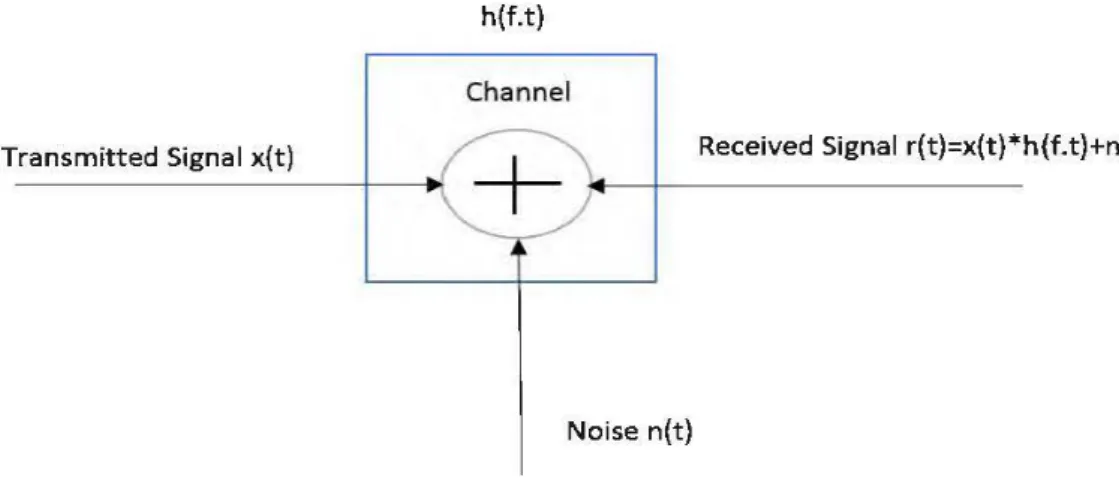
2.6. Communication Channel
To design a communication scheme, ail issues which may affect the propagation of the signal must be considered. Renee, there is a need to investigate the effects of fading and noise on mobile channels. Sorne typical communication channels are introduced in the following sub-section.
h{f.t) Cha nnel
Transmitted Signal x(t) Received Signal r(t)=x(t)*h(f.t)+n(t)
Noise n(t)
Figure 2.3: The additive noise channel
2.6.1. Additive White Gaussian Noise (AWGN) Channel
In this channel, the on1y impairment that encounters the propagation of the transmitted signal is the thermal noise, which associated with the physical channel itself, as well as the electronics at, or between, transmitter and receiver. In AWGN channel the signal is demeaned by white noise which has constant spectral density and a Gaussian distribution of amplitude. In this model h(f. t) is always assumed to be li(f. t) .
2.7. Stationary Channel Model
2.7.1. Rayleigh Fading Channel Model
In this mode!, channel is considered stationary. This type of fading occurs when there are multiple indirect paths between transmitters and receivers and no clear dominant path, such as an LOS path. It represents a worst-case scenario. It could be dealt with analytically by providing insights into performance characteristics that can be used in challenging environments, such as downtown urban settings. A Rayleigh random variable R has the probability distribution:
2r
(-r
2 ) PR(r) =-;;-*expD
2.7.2. Rician Fading Channel Model
In this mode!, channel is considered stationary which means that h(f. t) = h(f) fort. Rician fading describes a situation where there is a direct LOS path in addition to severa! indirect multipath signais and the distribution is found to be Rician. The pdf of such function is given by:
Where Œ2 is the variance of the in-phase and quadrature components. A is the
amplitude of the signal of the dominant path and /0 is the zero-order modified Bessel function of the first kind.
It is often applicable in indoor environments, smaller ce lis or more open outdoor environments. The channels can be characterized by a parameter K, defined as follows:
Power in the dominant path
K = - : : - - - : - - - : - - - : - ' - - .
Power in the scattered path
When K ~ 0, the channel is experiencing Rayleigh fading (i.e., numerator is zero) and when
K ~ w the channel is experiencing A WGN (i.e., denominator is zero) [38].
2.7.3. Nakagami-m Fading Channel Model
Stationary channel also considered in this model where h(f. t) = h(f) for
t.
Nakagarni-m Fading often applies to land-mobile, scintillating ionospheric and indoor-mobile links. The PDF ofNakagami-m is given by:x::O:O (2.7)
Where rn is the Nakagarni-m fading parameter in range of~ :S
m
:S co and r(.) is the2
gamma function defined as:
In the special case rn ~ 1, Rayleigh fading is recovered from (2. 7). For rn
>
1, the fluctuations of the signal strength reduce compared to Rayleigh fading.2.8.
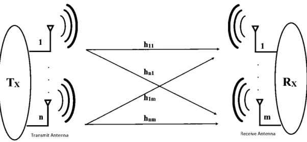
MIMO Communication System
A MIMO scheme uses multiple antennas at both the transmitter and receiver to improve the communication system performance by use of diversity and multiplexing techniques. MIMO system is a cost effective and it provides higher spectral efficiency,
improve throughput capacity, and advances the reliability, and improved resistance to interference [39].
~(
1Tx
Transmit Antenna Receive Antenna
Transmitter Receiver
Figure 2.4: MIMO Communication system.
There are three key MIMO techniques that have been proposed in the literature, such as, precoding, spatial multiplexing, and diversity coding. Precoding is a technique that uses the knowledge of CSI at the transmitter and the receiver to design precoder for multi-stream beamforming. In a situation where CSI is not available at the transmitter, diversity coding can be used to achieve better diversity gain like MRC system. In diversity coding method, the signal is transmitted by applying space-time coding at the transmitter.
A Basic MIMO system is illustrated in Figure 2.4. This MIMO system consists of n transmit antennas and rn received antennas. The channel between the
i
th receive antenna and the jth transmit antenna is denoted as h;j . Therefore, received signal can be modeled as:y=
Hx
+n
(2.8)Where y is the received signal vector, x transmitted signal vector, n is the noise vector and His the channel matrix where each (i,j) component represent the h;j .
2.9. Signal Encoding Technique 2.9.1. BPSK Modulation
BPSK is a simple form of phase shift keying which uses two phases, each separated by 180°. This modulation technique is the most robust of ali PSKs since it requires the maximal leve! of noise or distortion to commit the demodulator achieve a wrong decision. However, it on! y modulates at 1 bit/symbol which makes it quite unsuitable for high data-rate applications in limited bandwidth cases. The demodulator is usually unable to tell which constellation point is which when there is an arbitrary phase-shift introduced by the communications channel thus data is often differentially encoded before modulation [ 40].
----
.
Figure 2.5: Signal constellation diagram for BPSK The BER ofBPSK in AWGN cau be written as:
Pb= Q
(~)
or
Pb=~er fe(~)
Since there is on! y one bit per symbol, this is also the symbol error rate. Where:
• Eb ~ Energy-per-bit
• E5 ~ Energy-per-symbol ~ nEb with n bits per symbol
• Tb ~ Bit duration
• T5 ~ Symbol duration
•
~o_
Noise power spectral density (W/Hz)• Pb~ Probability ofbit-error
• Sb~ Symbol of bit b
2.9.2. QPSK Modulation
QPSK modulation technique uses four points on the constellation diagram, equispaced around a circle with all phases and can encipher two bits per symbol. When analyzed mathematically, it can be shown that BPSK can be used to twofold the information rate compared with a BPSK scheme while maintaining the same bandwidth of the signal orto retain the data rate of BPSK but halving the bandwidth needed. Due to bandwidth limitations, QPSK has an advantage because it transmits twice the data rate in a given bandwidth than BPSK does at the same BER. The only demerit is that QPSK transmitters and receivers are quite complicated thus more expensive. Contrasting encoded QPSK is often used in practice to counter the phase ambiguity problems at the receiving end [ 41].
As a result, the probability ofbit-error for QPSK is the same as for BPSK:
0
no 1u
Figure 2.6: Signal constellation diagram for QPSK
However, to achieve the same bit-error probability as BPSK, QPSK uses twice the power (since two bits are transmitted simultaneously). The symbol error rate is given by:
= 2Q
(ft!)_
Qz(ft!)
(2.10) If the SNR is high (as is compulsory for practical QPSK systems) the probability of symbol error may be approximated as:CHAPTER3
RELA Y AND COOPERATIVE COMMUNICATION
3.1.
Introduction
The progress of wireless communications from analog to digital led to the enhancement of earl y propagation models, which provided information about power, to also considertime and delay information. Further consideration of the space domain either with space diversity or smart antennas or, nowadays, MIMO systems has also pushed the evolution of propagation mode ling toward more complex spatiotemporal considerations. In wireless communication, users often suffer from channel fading where the signal attenuation varies significantly over the transmission. This can be overcome using proper diversity methods such as spatial, temporal, and frequency diversity. Achieving same collaboration between distributed relay nodes that help to establish a communication link between an origin transmitting node and a destination receiving node. Severa! theoretical studies have been carried out on cooperative communication, and these studies suggest that cooperation required Jess transmitted power at the origin and the relay node. It makes cooperative diversity is interference Jess and a power efficient communication method. Also, it enhances the coverage and the throughput of the system [42-45].
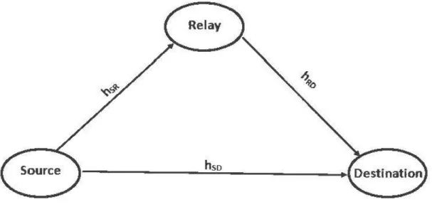
In this work, we study dual hop transmission, which is a three-node network consisting of a source, a destination, and a relay. Figure 3.1 illustrates a simple schematic of the dual hop communication system. Here, fading channels source-relay, re lay-destination, and source-destination are denoted as h5r,hrd and hsd• respectively. For this system, received signal at the relay node can be obtained as: [46].
Ysr =
~hsrX
+ nr
Where P5 is the average transmit power at the source, x is the signal transmitted at the
Figure 3.1: Dual-hop relay comrmmicat.ion.
Dual hop system can be classifi.ed into two broad categories, depending on how
the receive signal processing is done at the relay node. This can be split in two
sub-groups regenerative (decode-and-fOIW3fd) and non-regenerative
(amplify-and-forward) systems.
3.2.
Refa)• Function
Right. up till the present time, the limit of the general relay charmel alongside its
ideal relay fwtctions are obscure. Thus, severnl relay functions have been proposed in
the literature. Due to prnctical conslraint, relay opera:ting in the literalure are causal,
i.e., the signal transmitted by the relay at a given time can only be a function of
previously received signais. Basic relay fwtctions include decode-and-forward (DF),
compress-and- forward (CF), and amplifY-and-forward (AF).
3.2.1. Amplify and forward (AAF)
In
AF, the relay nodes receive the signal and forwards amplified signal to the
destination node. AF gives subsiilntial gains with using simpler signal processing. Not
only AF can be ernployed in practice, butit also has lower implementation loss, simpler implementation method, and very cost effective.
AF relaying scheme is illustrated in Figure 3.2 [47]. In the AF relaying system,
h5d, hsr, and h,.d to indicate the charmel coefficient of the source-to-destinationlink,
the source-to-relaylink, and the relay-to-destinationlink. The received signal Ysr at the rel a y node is subject to an amplification factor G be fore fmwarding it to the destination node. The received signal Y rd at the destination is given by equation:
Yrd = G_.J'P';flrdYsr
+
1lr (3.1)\Vhere Gis the complex channel gain betweenrelay andreceiver. PRis the average transnùt power at the relay.
Destina tio n
Figure 3.2: Arnplify and forward relaying system [72]
The AF relaying scheme can be classified into tw"o categories based on the availability of the channel station information (CSI) at the relay node, i.e., CSI assisted AF relaying and fixed gain AF relaying. The CSI assisted scheme adopts charmel rneasurements to compensate the instantaneous fading amplitudes ofthe source-relay link. The fixed gain scheme, in contrast, amplifies and forwards the received signal
with a fixed gain, which may either rely on average CSI information (i.e., semi-blind) or be CSI independent (i.e., blind relays) and such approach results in reduced processing overheads and implementation complexity at the relay. On the other hand, co-channel interference (CCI), caused by aggressive reuse of frequency in a cellular system, can dram atically degrade the performance of the system [ 48].
3.2.2. Decode and Forward (DAF)
In a DF relay scheme as shawn in figure 3.3 [45], Decoding is the reverse of encoding. It converts encoded data communication transmissions and files to their original states. The received signal is decoded and re-encoded (Y
sr)
to estimate x. Then the estimated signalx
is forwarded to the destination to complete the transmission. This signal estimation can be carried out in syrnbol by symbol or by the entire code ward by considering the system required performance and corn plexity at the re lay. The received signal Yrd at the destination can be obtained as:(3.2)
Where Pr is the average transmit power at the relay and nd is the noise at the destination.
Re~
h RD
Source
Destination
3.2.3. Compressed and Forward (CAF)
The compress-and-fotward (CF) scheme allows the re lay station to compress the received signal from the source node and fotward it to the destination without decoding the signal where Wyner-Ziv coding can be used for optimum compression. The Wyner-Ziv coding scheme is obtained by adding a quantizer and a de-quantizer to the Slepian-Wolf coding scheme. Therefore, a Wyner-Ziv coder design could focus on the quantizer and corresponding reconstruction method design.
3.3.
Half-Duplex Relay
Van der Meulen in 1971 [48] was first introduced the relay channel. Later, in the similar work of [ 47], Co ver and Gama! laid the foundation to the information-theoretic understanding of the re lay channel. Earlier theoretical works assumed that the relay could operate in full-duplex (FD) mode, i.e., the reay can transmit and receive data at the same time over the same frequency band [ 49-53]. This assumption was believed to be impractical due to the vast difference in transmitting and receive signal powers levels, which results in self-interference. Thus, motivated by wireless scenarios, the focus on the re lay channel was shifted to half-duplex (HD) operation.
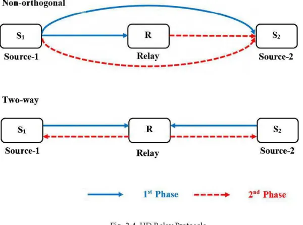
Pioneer works on HD were relaying focused on dual-hop strategies, e.g., [54-57]. In HD protocols, datais transmitted from source to destination through the relay in two phases as shown in figure 3.4. In the first step, the node of origin N1 sends to the re lay R, whereas the relay communication to the destination node N2. For the 3GPP next generation mobile communication systems, the dual-hop strategies can be easily implemented in practice to improve the network coverage of the network [30].
The half-duplex relay uses two main mies in transmission one is non-orthogonal, and the other is two-way. In two-way protocol, a cooperation composed of two-time slots: during the first time slot, the source communicates with the re lays and destination. In second time slot, when only the relays communicate with the
destination, the protocol is called as orthogonal or two-way. On the contrary, the protocol is not orthogonal when the both source and relays commnnicate with the destination. As shown in figure 3.4, the non- orthogonal relay does not send back the data, but it keeps it on forwarding. Node 51 sends data to both re lay and the 52 node in
the first phase, in blue (Continuous) line on Fig 3.4, while in the second phase, red (dot) line, the relay and 51 nodes send the data to the 52 node or destination again.
Two way, on the other hand, guarantees the success of transmission in two ways. The first phase is the sending path from 51 node to 52 node through the relay where the
second one is the opposite path from 52 to 51 node through the same relay node [59].
Non-orthogonal
[ s,
r===== •[
R}----~
,,
~~Source-1 ... Relay _._..,...,.. Source-2
---Two-way
(..____s---',
~-
__________
~'----R---'~-
__________ : (s,
l
Source-1 Re lay Source-2
t •t
Phase --·--~ 2nd PhaseFig. 3.4. HO Relay Protocols
In the protocols discussed above, node 51 wants to commnnicate to node 52 v1a
the relay, i.e., information flows from 51 to 52 (51 --t 52 ). These protocols can thus be
3.4.
Full-Duplex Relay
From the ab ove discussion, we can see that half-duplex constraint of the re lay has a significant impact on spectral efficiency on relay protocols. Full-Duplex (FD) wireless operation for this part has been shown to be practicable through a novel combination of self-interference (SI) mitigation scheme [60-64]. In particular, to avoid saturating the receiver front end, severa! techniques be fore analog-to-digital conversion have been proposed. For instance, basic analog cancellation methods include antenna separation [60-62], orientation [60] and directionality [65]. Despite these advances in cancellation techniques, the self-interference remains a challenge as it cannot be completely mitigated in practice. As such, different from earlier information theoretical works, the self-interference must be explicitly taken into account when assessing, designing and analyzing FD protocols.
Similar to HD schemes, FD protocols can be classified depending on whether the direct source-destination link is used or not in transmission. In fact, the idea of cooperative relaying can be traced back to the works of van der Meulen and Co ver in [ 48,49], respectively, which make use of the direct link for FD communication. Specifically, in FD relaying schemes, the source transmits to the relay and the destination, while the relay simultaneously receives the signal from the source and transmits to the destination, as shown in Fig. 3.5. Similar to their HD counterparts, FD dual-hop relaying has two main limitations when the direct connection is not under heavy shadowing. First, although the source is allowed to transmit continuously, the rate of the FD dual-hop scheme might be degraded due to the self-interference created at the destination node from the direct link. Furthermore, this protocol does not provide any diversity benefits. Thus, as in the HD scenario, cooperative FD techniques that make use of the direct link for transmission might be able to off er data rate and diversity advantages.
Dual-hop .... -~~ ~ - ~~~~ ~~
,,
(
St
r
i
R
}
'~'--S-2
___,) \ Il Source-1(
_ _
s.
r===
Source-1 \ 1'
'-~,
Re layi
R}
1 \ 1 \ 1 \,
',-~ Relay Source-2~
s2
]
Source-2---+
Self-interferenceFig.3.5. FD Relay Protocols
It is important to note that for both FD protocols in Fig. 3.5, the potential gains of FD relaying might not be realizable due to the level of residual self-interference at the relay node. Renee, the ideal FD schemes previously proposed in the literature need to be re- analyzed under such scenario.
3.
5.
Cooperative VS Relaying Communications
The concept of cooperative relaying is a promising means to counteract the effects of small-scale fading. It builds on the idea of cooperative diversity and exploits alternative communication paths by getting assistance from other nodes in the area of sender and receiver of a currently exaggerated communication link. These additional no des act then as relays, i.e., a dedicated or temporarily chosen wireless node that helps in forwarding information from a source node to a destination node. The relayed
information flow as a result of this creates a communication path concurrent to the direct communication flow from source to destination or communication via other re lays. The relay channel model includes a source node, a relay node, and a destination node, as shown in Figure 3.1.
The work in [52], was based on the analysis of the capacity of a three-node network consisting of a source, a relay, and a receiver. The assumption was that all links function in the same frequency band. Therefore, the system could be decomposed into a broadcast channel concerning the source and a multiple access channels concerning the destination. While mostly analyzed capacity in an A WGN channel, the motivation now is more on the concept of diversity in a fading channel. Secondly, in work on the relay channel, the relay's sole aim is to aid the main channel, whereas, in cooperative communication, the total system resources are fixed, and users act both as information sources as well as relays [67]. Therefore, although the historical importance of the first works on relay channel is indisputable, recent work in cooperation has taken a somewhat different emphasis [68].
3.6.
MIMO Relaying
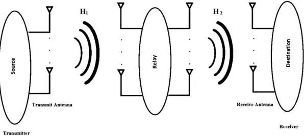
The MIMO relaying is fascinating research direction that can optimally make use of the main resources ofwireless fading channel, and attain the benefits ofboth MIMO and cooperative communication. We investigate the MIMO relaying systems in our
study, such as two stage projection based FD amplify and forward MIMO relying.
Receive Antenna
Receiver Transmitter
Fig. 3.6: MIMO cooperative communication system.
Iwo stage projection algorithms based FD-MIMO relaying systems can be used to im prove the link reliability wh en a self-Interference is present between the source and transmitter. In this case, it is important to have multiple antenna at the transmitter to apply two stage projection. The receiver (relay, destination) can be either single antenna or multiple antenna. In chapter 4, we discuss further on two stage projection based FD-MIMO relaying system.
CHAPTER4
PROPOSED
FD-MIMO
RELA Y
4.1. Introduction
This chapter focuses on relay self-interference cancellation v1a two-stage projection. The projection algorithm applied through this chapter depending on the matrix rank.
The interference creates in the relay node when the unwanted signal sources are added to the primary signal, and it is the main reason for the signal corruption. In
relaying communication, signal travel from a source to a destination is decidedly affected by the interference generated by other deviees. In this way, if deviees in the zone of the receiver transmit at the same time and on the same frequency, their signais interfere at the receiver with the useful signal from the sender and thus block appropriate reception. The CCI cause high error rates, and this has a vast destructive impact on the system performance. In general, CCI in a relaying system can be considered either at the relay, destination or both relay and destination node. As mentioned previously, most of the existing works are based on zero-forcing, minimum mean error square and null space projection. Though, in wireless communication networks, the interferences signais can cause different involvement attenuation, particularly in cellular networks. This main constraint motivated current study to derive a new mathematical analysis of a realistic situation. This mode! considers an AF relay system over Rayleigh fading channels in the presence of interferences at relay node. Therefore, the system mode! considered in this chapter is adequate for indoor wireless communication.
The main contribution of this the sis work is that a new mathematical method for accurate and efficient cancellation of SI around the relay, evaluate the bit error rate performance of amplify and forward FD-MIMO relays system for different modulation scheme.
4.2. The Relay System Mode[
Considera three-link dual-hop amplifies and forward (AF) relaying system in the indoor wireless system. AF relay protocol is defined for cooperative relay communication, i.e. , it improves the perfonnance of the wireless communication system. AF relay an1plifies its received signal and maintaining fixed average transmit power. In our re lay system model, AF is employed be cause it requires relatively simple signal processing.
1-h-...R.
:Relay (R)
H L.I Loop rock s igmal (or·~
Self tnterl~ërt«:
Fig.4.1: Two-hop relay model.
The relay model includes Transmitter(Tx), Relay (R) and Receiver (Rx) nodes shown in Fig.4.1. The transmitter node is equipped with a set of Nrx antennas whereas the receiver node has N Rx antem1as. The re lay node is equipped with two sets of
antennas. The first set, have (NR)antem1as and is dedicated to receiving meanwhile the second set include (Nr )transmit antem1as.
which represent respectively the MIMO complex cham1el matrices from the transmitterto relay node and from the relay node to a receiver. The signal vector x(n) defined as a complex vector x(n) E <CNTxxt,
transmitted by the source node. The complex signal vectors r(n) andt(n). stated as
r(n) E ICNRx 1and t(n) E cNrxt, denote the received and transmitted signal at the relay
node respectively. Huis the loopback self-interference signal which reduces the channel capacity from the transmission to reception and makes the relay system unstable in FD MIMO. The self-interference complex channel matrix, induce by the relay, is denoted by HuE ICNRxNr, as showninfigure 4.1.
4.3.
Proposed Two Stage Projection Approach
Proposed two stage projection algorithm (TSPA) consist of null space projection (NSP) and subspace projection (SP).
4.3.1. Projection
A projection matrix P is a
n
xn
square matrix that gives a vector space projection from !Rl.n to a subspace w. The columns of P are the projections of the standard basisvectors, and
w
is the image of P. A square matrix Pis a projection matrix if and only if P2 =P. An orthogonal projection is a projection for which the range and the null space are orthogonal subspaces. A projection is orthogonal if and only if it is self-ad-joint, which means that, in the context of real vector spaces, the associated matrix is symmetric relative to an orthonormal basis:p = P'. Where P' denoted as ad-joint matrixof P. The projection randomly selects the 'closet' subspace onto the matrix. For example, a linear system like Ax = b which does not have a solution, may be approximated by a linear system A x =
b
for which there does exista solution and where the vectorb
is chosen so that it is close to b.4.3.2. Null Space Projection (NSP)
Null space projections are distinct by their null space and the origin vectors used to describe their range. When these base vectors are orthogonal to the null space, then
the projection is an orthogonal projection and where one projects a vector, onto a subspace and the vector in the subspace which is "closest" to the same vector. An
example, in NSP the spatial receive and transmit filters are selected such that the transceivers receives and transmits in different subspace i.e., transmit beams are projected to the null-space of the loopback SI channel combined with the receive filters and vice versa.
4.3.2. Subspace Projection (SP)
The subspace is known as the column space of the matrix A. Subspace consists of ali possible values of the vector x. It is precisely the subspace of Kn spanned by the column vectors of A. The row space of a matrix is the subspace spanned by its row vectors. When one projects a vector v onto a subspace, the vector in the subspace which is "closest" to v. The simplest case is of course ifthe vector is already in the
subspace, then the projection of onto the subspace is the vectoritself.
According to the multipath propagation, proposed scheme splits into two cases.
4.3.4. Flat Channel Case
In this case, the multipath parameter of the channel dis smaller than signal symbol time (Ts), which means that the one symbol will interfere mainly with itself. The signal received by the re lay is expressed as,
r(n) = HrxRx(n)
+
Hut(n)+
w(n) (4.1) Where w(n) E ICNRx1denote an additive white Gaussian noise (AWGN) and Hut(n)is the loopback interference signal received by the re lay. Where t(n) is the transmitted signal in the relay.
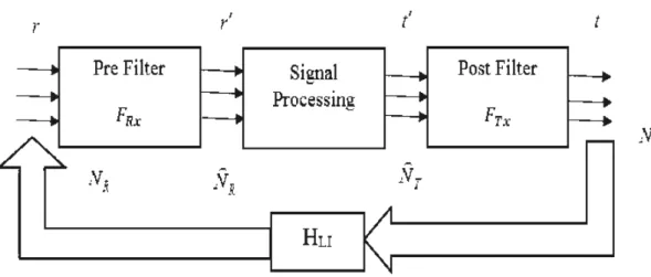
Fig . 4 .2: Re lay loopback inte1femce cacellation by us ing TSPA scheme. A pre-projection filter, w hich is cal led the loop back signal suppression filter denoted by
FRxand
defined asFRx
E f.NRxFJR and post filterwhich is called transmitweight filer
Frx
defined byFrx
E r,RrxNr are depicted in fig.4.5. Without Joss ofgenerality, we can assume that
NR
=::;NR
andNr
=::;Nr
because the end to end communication cannot improve by the increasing the number of dimensions. The output signal of the pre-filter r'(n) E éRx t and the input signal of the post filtert' (n)
E r,Nrxt.Now, the output of the pre-filter r ' (n) with loop back interference can be written as,
(4.2) In equation 4.2, the first part represents the desired signal exposed to white Gaussian noise and the second part is channelloopback inte1ference.
As shown in fig. 4.2, relay used two adaptive filters, pre-filter
FRx
and post filterFrx
to respectively process the input and output signal in 01·der to cancel the SI. Which means that both filters will collaborate
to
define the right message to send with a view to suppressing the channel loopback interference. To achieve this goal, according to equation 4.2, the second prut should be zero (cf. equation 4.3) is a necessary and sufficient condition to optimize both adaptive fi l ter weights.( 4.3) 4.3.5. Selective Frequency Case
For this case, the maximum multipath d induced by the channelloopback is more thau one-time Ts duration. The number of subsequent symbols that interfere with one symbol, denoted by L, is estimated by equation 4.4.
[ d+
Tsl
L = - - '
Ts
(4.4)Now, according to the mode! in fig.4.3 and due to the inter symbol interference the output signal f (
n)
is rewritten as,f(n) = {FRx(HrxRx(n)
+
w(n))}
+
{FRxHuT(n)} (4.5) Where T(n) = [t1(n) t2(n) tNr(n)Yis anarrayofrelayoutcomingsignals,one per transmitting antenna and defined as:
t(n) = [t;(n) t;(n -1) t;(n- L
+
1)] (4.6) The t; (j) is the transmit signal by the i th re lay antenna at sample time j. The output of the post filter re lay node is,t(n) = Frxt'(n) (4.7)
Where
t' (
n) indicated the input signal of the post filter. Let,t' (
n) =[t' 1 (n),
t'
2 (n),Substitute equation (4.7) in equation (4.5) we get,
r'(n) = {FRx(HrxRx(n)
+
w(n) )}+
{FRxHuGTén)} (4.8) Where T' (n) = [ {1 (n) {2 (n)t
fJr]
T andG
is the diagonal matrix of theadaptive filters.

![Figure 3.2: Arnplify and forward relaying system [72]](https://thumb-eu.123doks.com/thumbv2/123doknet/7651790.237531/37.918.171.699.494.775/figure-arnplify-forward-relaying.webp)
![Figure 3.3: Decode and forward relaying system [72]](https://thumb-eu.123doks.com/thumbv2/123doknet/7651790.237531/38.918.206.664.743.972/figure-decode-and-forward-relaying-system.webp)