ÉCOLE DE TECHNOLOGIE SUPÉRIEURE UNIVERSITÉ DU QUÉBEC
MANUSCRIPT-BASED THESIS PRESENTED TO ÉCOLE DE TECHNOLOGIE SUPÉRIEURE
IN PARTIAL FULFILLMENT OF THE REQUIREMENTS FOR THE DEGREE OF DOCTOR OF PHILOSOPHY
Ph.D.
BY
Cristóbal OCHOA LUNA
NONLINEAR CONTROL OF A SEVEN DEGREES-OF-FREEDOM EXOSKELETON ROBOT ARM
MONTREAL, MARCH 21, 2016
© Copyright
Reproduction, saving or sharing of the content of this document, in whole or in part, is prohibited. A reader who wishes to print this document or save it on any medium must first obtain the author’s permission.
BOARD OF EXAMINERS
THIS THESIS HAS BEEN EVALUATED BY THE FOLLOWING BOARD OF EXAMINERS
Mr. Maarouf Saad, Thesis Supervisor
Department de genie électrique, École de technologie supérieure
Mr. Guy Gauthier, Chair, Board of Examiners
Département de génie de la production automatisée, École de technologie supérieure
Mr. Vahé Nerguizian, Member of the jury
Département de génie électrique, École de technologie supérieure
Mr. Philippe S. Archambault, Member of the jury
School of Physical & Occupational Therapy, McGill University and Centre of Interdisciplinary Research in Rehabilitation (CRIR)
Mr. Wael Suleiman, Independent External Evaluator
Electrical and Computer Engineering Department, Engineering Faculty, Université de Sherbrooke
THIS THESIS WAS PRESENTED AND DEFENDED
IN THE PRESENCE OF A BOARD OF EXAMINERS AND THE PUBLIC ON JANUARY 21, 2016
FOREWORD
The present work is part of the project that has as final objective to develop an upper arm robotic exoskeleton to perform a variety of rehabilitation tasks as well as help in daily life activities. Design and construction of the robot as well as the first control approaches and passive rehabilitation schemes were developed in the work of Mohammad H. Rahman in his Ph.D. studies at École de technologie supérieure (ETS), research summarized in the thesis cited below. Also the work of Thierry Kittel-Ouimet in his M.Sc. studies at ETS yielding to the thesis also cited below.
1. Kittel-Ouimet, Thierry. 2012. « Commande d'un bras exosquelette robotique à sept degrés de liberté ». Master in electric engineering thesis. Montréal, École de technologie supérieure, 154 p.
2. Rahman, Mohammad Habibur. 2012. « Development of an exoskeleton robot for UPPER-LIMB rehabilitation ». Doctor of Philosophy thesis. Montréal, École de technologie supérieure, 206 p.
ACKNOWLEDGMENTS
I wish to express my deepest gratitude to my advisor, Dr. Maarouf Saad for all his teachings and the shared knowledge; but especially his invaluable guidance, patience and his enormous qualities as a mentor and as a person. Without them, the achievement of the present work would have not been possible.
I want to thank as well all my research team: Dr. Philippe S. Archambault, Dr. Jawhar Ghommam, Dr. Wen-Hong Zhu, Dr. Mohammad H. Rahman, Abdelkrim Brahmi, Thierry Kittel-Ouimet and Bruce S. Ferrer for their important contributions to this research. Also I want to thank Dr. Guy Gauthier, Dr. Aimé Francis Okou and Dr. Ilian Bonev for their teaching during the initial part of my studies. I wish to express my gratitude to Dr. Maarouf Saad, Dr. Guy Guthier, Dr. Philippe S. Archambault, Dr. Vahé Nerguizian and Dr. Wael Suleiman for being part of the committee who agreed to review and evaluate this research work. Thanks to Dr. Kash Khorasani for his contribution in my education.
I would like to thank the National Council on Science and Technology of Mexico (CONACYT) for the support under grant No. 211951 jointly with Professor Maarouf Saad and École de technologie supérieure, for the most part of my studies. As well as for the important financial support that Dr. Saad provided in the final part of my studies.
Overall, I want to express my warmest thanks to my parents and sister for their unconditional love and support in all possible ways. To the rest of my family that always supported me in many different means, welcomed me on vacations with all the affection and warmness and forgave the extremely short time that I could spent with them during the last six years.
My most sincere thanks to my friends, back in Mexico and the ones that I made here in Canada; for sharing so many fun and stress-relieving moments, as well as the support and encouragement.
COMMANDE NON LINÉAIRE D'UN BRAS EXOSQUELETTE ROBOTIQUE À SEPT DEGRÉS DE LIBERTÉ
Cristóbal OCHOA LUNA RÉSUMÉ
Les progrès dans le domaine de la robotique ont permis l’intégration de plus en plus de dispositifs robotisés pour la réadaptation des personnes avec un handicap physique. Ce travail de recherche englobe tout le domaine de la robotique de réadaptation; il présente l’évolution du robot ETS-MARSE, un exosquelette à sept degrés de liberté destiné à être porté par le bras humain. Les développements incluent l’étude et l’implémentation d’une approche de contrôle non linéaire relativement nouvelle, ainsi que différents programmes de réadaptation.
Une des caractéristiques d’un robot de réadaptation est qu’il est utilisé par un grand nombre de patients qui ont des conditions physiologiques et biomécaniques diverses. L’implémentation de la technique de contrôle non linéaire, connue sous le nom de Virtual Decomposition Control, atteint cette exigence grâce à son adaptation de paramètres internes qui présente un comportement robuste pour les différentes caractéristiques des utilisateurs de robot. En outre, cette technique simplifie la complexité des robots possédant de hauts degrés de liberté par son innovante décomposition du système. De plus, elle lui assure une stabilité asymptotique et un excellent suivi de trajectoires.
Parmi les différents programmes de réadaptation, nous pouvons nommer : la réadaptation passive, la réadaptation active-assistée et la réadaptation active. La première suit des trajectoires prédéfinies et s’appuie sur l’efficacité du dispositif de commande. Les deux autres programmes ont besoin d’une méthode de compréhension de l’intention du mouvement de l’utilisateur; ils peuvent donc prendre une action de suivre, guider, retenir ou corriger le mouvement. À cet effet, notre première approche utilise un capteur de force comme l’interface humain-robot afin de transformer, par l’intermédiaire d’une fonction d’admittance, les forces que l’utilisateur exerce sur l’effecteur du robot et exécuter la réadaptation active-assistée ou la réadaptation active. Enfin, entre les principaux développements de ce travail, une approche est présentée, dans laquelle la nécessité d’un capteur de force pour effectuer certaines tâches de réadaptation active est supprimée. Au moyen d’un observateur non linéaire, les forces d’interaction sont estimées et l’intention de mouvement de l’utilisateur s’ensuit. Les résultats expérimentaux montrent l’efficacité de toutes les approches proposées. Tous les essais qui ont été faits sur des humains ont été testés avec des sujets qui ne présentent aucun handicap.
Le suivi de trajectoires du robot est exécuté dans l’espace articulaire; certaines trajectoires sont données dans l’espace cartésien et transformées à l’espace articulaire en utilisant la technique du pseudo-inverse de la matrice jacobienne. Cependant, cette option est limitée; la prochaine étape obligatoire pour améliorer les nombreuses fonctions du robot est de résoudre sa cinématique inverse. Parmi les autres progrès qui sont en développement, l’une d’entre
elle est une approche pour la classification et la modélisation des signaux électromyographiques afin d’obtenir des informations auprès des utilisateurs du robot. Les premiers résultats utilisant cette méthodologie sont présentés. La téléopération et les capacités haptiques sont également dans la phase initiale de développement.
Mots-clés: 7DDL réadaptation exosquelette, Virtual Decomposition Control, réadaptation active, réadaptation active-assistée, admittance, observateur non linéaire
NONLINEAR CONTROL OF A SEVEN DEGREES-OF-FREEDOM EXOSKELETON ROBOT ARM
Cristóbal OCHOA LUNA ABSTRACT
Advances in the field of robotics have allowed increasingly integrating robotic devices for rehabilitation of physical disabilities. This research work is encompassed into the field of rehabilitation robotics; it presents the development of the robot ETS-MARSE, a seven degrees-of-freedom exoskeleton designed to be worn in the human arm. The developments include the study and implementation of a relatively novel nonlinear control approach, as well as different rehabilitation schemes.
One of the characteristics of a rehabilitation robot is that it deals with a wide number of patients that have different biomechanical and physiological conditions. The implementation of the nonlinear control technique known as Virtual Decomposition Control addresses this issue with its internal parameters’ adaptation that presents a robust behavior to different characteristics of the robot users. Besides, this technique simplifies the complexity of high degree-of-freedom robots by its innovative sub-systems decomposition. All of above, while ensuring the system asymptotic stability and excellent trajectory tracking.
Between the different rehabilitation schemes, we can mention: passive, active-assistive and active rehabilitation. The first one follows predefined trajectories and relies on the efficiency of the controller. The two other schemes require understanding the user’s intention of movement and take an action in order to guide, restrain, correct or follow it. For this purpose, we present an approach that utilizes a force sensor as the human-robot interface in order to transform, via an admittance function, the forces that the user exert to the robot end-effector (handle), and execute active-assisted or active rehabilitation. Finally among the main developments of this work, an approach is presented in which the need of a force sensor to perform some active rehabilitation tasks is removed. By means of a nonlinear observer, the interaction forces are estimated and the user’s intention of movement followed. Experimental results show the effectiveness of all the proposed approaches. All the tests involving humans were tested with healthy subjects.
Trajectory tracking of the robot is executed in joint space; some trajectories are given in Cartesian space and transformed to joint space by means of the pseudoinverse of the Jacobian technique. However this option is limited; a mandatory next step to improve many functionalities of the robot is to solve its inverse kinematics. Between other progresses that are in development, is an approach to process electromyographic signals in order to obtain information from the robot’s users. First results on this methodology are presented. Teleoperation and haptic capabilities are also in the initial stage of development.
Keywords: 7DOF rehabilitation exoskeleton, Virtual Decomposition Control, active rehabilitation, active-assistive rehabilitation, admittance, nonlinear observer
TABLE OF CONTENTS
Page
INTRODUCTION ...1
CHAPTER 1 RESEARCH PROBLEM ...5
1.1 Literature review ...6
1.1.1 Overview of control inputs and control strategies ... 7
1.1.2 End-effector type upper-limb rehabilitation robots state of the art ... 8
1.1.3 Exoskeleton type upper-limb rehabilitation state of the art robots ... 9
1.1.4 Limitations of current approaches ... 10
1.2 Research objectives and methodology ...10
1.2.1 Development of the nonlinear control law ... 11
1.2.2 The sensing interface ... 11
1.2.3 Inverse Kinematics... 11
1.2.4 Implementation and experimentation ... 12
1.3 Originality of the research and contribution ...12
CHAPTER 2 VIRTUAL DECOMPOSITION CONTROL OF AN EXOSKELETON ROBOT ARM ...15
2.1 Introduction ...16
2.2 Characteristics of the Motion Assistive Robotic Exoskeleton for Superior Extremity ...20
2.3 Analysis of the ETS-MARSE robot with Virtual Decomposition Control (Zhu et al., 1997) ...22 2.3.1 Kinematics ... 23 2.3.2 Dynamics ... 25 2.3.3 Control ... 29 2.3.4 Stability Analysis ... 31 2.4 Experimental Results ...34
2.4.1 Varying subjects experiment ... 35
2.4.2 Varying velocity experiment... 40
2.4.3 Active rehabilitation experiment ... 42
2.4.4 Parameter adaptation ... 43
2.4.5 Discussion of experimental results ... 45
2.4.6 Safety ... 45
2.5 Conclusions and Future Work ...46
CHAPTER 3 ADMITTANCE-BASED UPPER LIMB ROBOTIC ACTIVE AND ACTIVE-ASSISTIVE MOVEMENTS ...49
3.1 Introduction ...50
3.2 System Overview ...53
3.3 Virtual Decomposition Control of the ETS-MARSE ...55
3.3.2 Kinematics ... 57
3.3.3 Dynamics ... 59
3.4 Active-assistive and active rehabilitation ...63
3.4.1 Trajectory planner ... 63
3.4.2 Active-assistive rehabilitation based on an admittance-modified trajectory planner ... 65
3.4.3 Active rehabilitation based on an admittance-modified trajectory planner ... 66
3.5 Experimental results...70
3.5.1 Active-assistive rehabilitation ... 70
3.5.2 Active rehabilitation, constrained free movement ... 73
3.6 Conclusions ...76
CHAPTER 4 COMPLIANT CONTROL OF A REHABILITATION EXOSKELETON ROBOT ARM WITH FORCE OBSERVER ...77
4.1 Introduction ...78
4.2 Nonlinear control: Virtual Decomposition Control and Force Observer ...81
4.2.1 Nonlinear force observer ... 81
4.2.2 Stability Analysis ... 85
4.2.3 Admittance control ... 87
4.3 Experimental results...88
4.3.1 System architecture ... 88
4.3.2 Joint space task ... 90
4.3.3 Cartesian space task ... 93
4.4 Conclusions ...95
DISCUSSION OF THE RESULTS ...97
CONCLUSION ...99
RECOMMENDATIONS ...101
ANNEX I ADITIONAL AND FUTURE WORK: ELECTROMYOGRAPHY, TELEOPERATION AND HAPTIC CAPABILITIES ...109
ANNEX II VIRTUAL DECOMPOSITION CONTROL ...115
LIST OF TABLES
Page
Table 1.1 End-effector type upper-limb rehabilitation state-of-the-art robots ...8
Table 1.2 Exoskeleton type upper-limb rehabilitation state-of-the-art robots ...9
Table 2.1 ETS-MARSE Modified Denavit-HartenbergParameters ...22
Table 2.2 Varying subjects experiment range of motion ...37
Table 2.3 Statistical analysis of performance variation ...39
Table 2.4 RMS error of varying velocity experiments ...40
Table 3.1 ETS-MARSE Denavit-Hartenberg modified parameters ...56
Table 3.2 Robot active-assistive rehabilitation reference trajectory ...71
LIST OF FIGURES
Page
Figure 1.1 Methodology ...12
Figure 2.1 Joint range of motion of ETS-MARSE ...20
Figure 2.2 7DOF Exoskeleton robot arm ...21
Figure 2.3 Virtual decomposition into 14 subsystems ...23
Figure 2.4 Block diagram of the system (with the equations used in each step in the parentheses)...30
Figure 2.5 ETS-MARSE with human subject ...34
Figure 2.6 Experimental setup with control architecture ...35
Figure 2.7 Schematic diagram, reaching movement exercise ...36
Figure 2.8 RMS joint tracking error along the 28 tests for each controller ...38
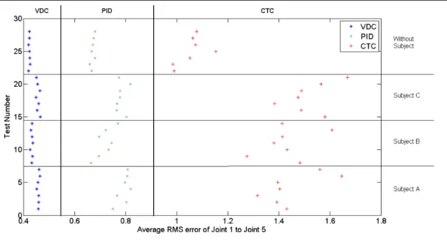
Figure 2.9 Average (joint 1 to joint 5) RMS error of each test ...39
Figure 2.10 VDC results for different speeds test ...41
Figure 2.11 PID results for different speeds test ...41
Figure 2.12 Experimental setup for active rehabilitation ...42
Figure 2.13 Cartesian trajectory, forces and torques for active rehabilitation ...43
Figure 2.14 Left: Robot initial position. Right: Joint 4 trajectory ...44
Figure 2.15 Parameter adaptation of joint 4 ...44
Figure 3.1 Subject wearing ETS-MARSE robot arm ...54
Figure 3.2 ETS-MARSE system hardware overview ...55
Figure 3.3 7DOF exoskeleton robot arm ...56
Figure 3.4 Virtual decomposition in 14 subsystems ...57
Figure 3.6 Block diagram of the system...67
Figure 3.7 Active rehabilitation with walls ...68
Figure 3.8 Virtual wall collision and reset path ...69
Figure 3.9 Active-assisted rehabilitation with walls ...69
Figure 3.10 Reference trajectory tracking ...70
Figure 3.11 Trajectory modified with high degree of help ...72
Figure 3.12 Trajectory modified with low degree of help ...72
Figure 3.13 Comparison of forces-torques between high and low degree of assistance from the robot ...73
Figure 3.14 Virtual walls as obstacle for active rehabilitation ...74
Figure 3.15 Virtual walls as obstacle and starting point for robotic assistance in active rehabilitation ...75
Figure 4.1 7DOF exoskeleton robot arm ...82
Figure 4.2 Subject wearing ETS-MARSE robot arm and virtual interface ...90
Figure 4.3 Joint space exercises ...91
Figure 4.4 Joint space exercise estimated torques and joint positions ...91
Figure 4.5 Joint 3 position and estimated and measured force for joint space test ...92
Figure 4.6 Cartesian space trajectory test results ...93
LIST OF ABBREVIATIONS AND ACRONYMS DOF Degrees-of-freedom
CRIR Interdisciplinary Research Center in Rehabilitation CTC Computed Torque Control
DC Direct Current
EBC Electromyographic Based Control EMG Electromyographic ETS École de technologie supérieure FBC Force Based Control
FPGA Field Programmable Gate Array HMI Human Machine Interface
MARSE Motion Assistive Robotic-exoskeleton for Superior Extremity mDH Modified Denavit-Hartenberg parameters
PD Proportional-Derivative PI Proportional-Integral
PID Proportional-Integral-Derivative RMS Root-Mean-Square
SMC Sliding Mode Control
SCARA Selective Compliant Assembly (or Articulated) Robot Arm
UE Upper Extremity
US United States
LIST OF SYMBOLS AND UNITS OF MEASUREMENTS UNITS OF MEASUREMENT ° or deg degree µs microsecond σ standard deviation A ampere cm centimeter g gram Kg kilogram m meter mNm millinewton meter ms millisecond N newton Nm newton meter
rpm revolutions per minute
s or sec second
V volt W watt SYMBOLS
αi-1 angle from to , measured about
ai-1 length from to , measured about
di distance from to measured about
, , Unitary vectors of the Cartesian coordinate system main axes. force/moment transformation matrices from frame to frame linear/angular velocity vector of frame { }
augmented velocity vector VDC Jacobian matrix
augmented required velocity vector link parameters vector
estimated parameters vector ∗ required net force/moment vector
required force/moment vector
∗ net torque for the joint
link force/moment vector control torque in Nm
INTRODUCTION
Since the beginnings of robotics, robots have been associated with human beings. In fact, their first activity was their use in the industrial environment to replace or help people in repetitive, dangerous or tedious tasks, and those that require high precision. Subsequently the relation was enriched with a greater exchange of information, for example in areas as robot teleoperation and service robots; nowadays, the relation has arrived at the level of cognitive and physical interaction in the called wearable robots. These robots can be defined as: “those worn by human operators, whether to supplement the function of a limb or to replace it completely” (Pons, 2008).
We can classify wearable robots into two general types, prosthetic and orthotic robots. The first ones have the purpose of replacing a member lost by amputation; the second ones, also called exoskeletons, map the structure of the limb and adapt to it to re-establish or to complete some functional lost. Among the purposes for the wearable robots we can mention: the increase of power, e.g. military applications; teleoperation, e.g. aerospace industry; and rehabilitation, in which our research work is focused. Additionally we can classify them, in a general way, as upper-limb and lower-limb exoskeletons, depending if they are worn in the arms or in the legs respectively.
This thesis presents the development of a robotic orthosis for the upper-limb to be used in rehabilitation, the robot ETS-MARSE (Motion Assistive Robotic-exoskeleton for Superior Extremity). The ETS-MARSE has seven degrees of freedom (DOF) designed to correspond with the main DOF of the human arm at shoulder (3DOF), elbow (1DOF) and wrist (3DOF) levels. The developments included in this work are the study and implementation of a novel control approach and some passive, active-assisted and active rehabilitation schemes. In rehabilitation when assistance is mandatory or might be needed, a therapist, apparatus or robot could participate; in our case, the proposed robot will be in charge of the assistance according to the necessary rehabilitation scheme. Passive rehabilitation is the kind of rehabilitation in which the subject should not provide effort and the rehabilitation task is
carried out by the robot. Active-assisted rehabilitation is the kind of rehabilitation where the subject receives partial assistance from the robot. In active rehabilitation, the subject performs the exercise by itself and the robot became the object of the exercise and an excellent way to measure the subject’s performance.
The ETS-MARSE is commanded in passive mode by pre-generated trajectories, either in joint space or Cartesian space, which correspond to different rehabilitation exercises. In active-assisted mode the predefined trajectory is followed by the robot, but it is allowed to be modified by the user in variable degrees. In active mode, the robot responds to the user intention of movement by following it and only assists according with time and spatial constrains.
The first chapter of this document describes the research problem. First, the chapter presents the identification and justification of the research problem, where the problematic that validates the present project is presented. A review of the existing literature is given and the outline of the state of the art of this area of research. Immediately, the objectives of the project, so much general as specific, are declared. Finally, it is presented an overview of the methodology used.
The second chapter presents the first paper of this research work. It is called “Virtual Decomposition Control of an Exoskeleton Robot Arm” and was published in Robotica in October, 2014 (Ochoa Luna et al., 2014b) (on-line version). This paper deals with two important issues in rehabilitation robotics: The first one is the capacity to adapt to different patients without significantly varying its performance. It is demonstrated that VDC through its internal parameter adaptation is capable to adapt to the whole robot-human system and have a robust behavior in comparison with Computed Torque control and PID control. The second is that with the novel subsystem decomposition of the VDC, the dynamics of the ETS-MARSE (a 7DOF robot) results in simpler dynamics to be handled by the control computation.
The third chapter is the second journal paper titled “Admittance-Based Upper Limb Robotic Active and Active-Assistive Movements” and was published online in the International Journal of Advanced Robotic Systems in September, 2015 (Ochoa Luna et al., 2015). It deals with the first approach to active-assisted and active rehabilitation modes. Both approaches uses the VDC control encompassed in a compliant control. The active-assistive approach uses the virtual work principle and an admittance function to transform the measurements from a force sensor (in the handle of the robot) into trajectory variations that allows the system to understand the user’s intention of movement. The admittance is anchored to a predefined trajectory; this allows, by changing its coefficients (spring and damping) to provide more or less degree of help to the user. In the active approach, this anchor is detached and the force transformation results on real-position differentials instead of trajectory ones; allowing the subject to move freely in space. A virtual environment is presented to guide the movement in the first case and in the second to restrain the free environment by virtual walls.
The fourth chapter contains the third research paper titled “Compliant Control of a Rehabilitation Exoskeleton Robot Arm with Force Observer” that was send to the IEEE/ASME Transactions on Mechatronics in March 2016. In our research we realised that the use of a force sensor to guide the movements of the robot, especially at the handle level, could easily result in the damage of such sensor. Also the high cost of elaborated sensors presents a problem for this kind of robots, among other complications. This third paper shows how a nonlinear observer could be used to estimate the user intention of movement instead of a force sensor. The observer successfully estimates the interaction forces between the subject and the robot, and uses this information through a compliant control, as in the second paper, to follow the user’s intention of movement.
After, the discussion of the results and the conclusion of the thesis based in the manuscripts described above are given. Finally, to present the additional content, Annex I presents results of this research that were not encompassed in the three main papers product of this thesis; as well as the present and future work for the ETS-MARSE. Between the results shown is an
approach to process and read information from electromyographic (EMG) signals. This method was used in another journal paper: “EMG Based Control of a Robotic Exoskeleton for Shoulder and Elbow Motion Assist”, published in the Journal of Automation and Control Engineering in 2015 (Rahman et al., 2015a); as well as in combination with the force sensor control described in Chapter 3, in the paper: “Force-Position Control of a Robotic Exoskeleton to Provide Upper Extremity Movement Assistance” published in the International Journal of Modelling Identification and Control in 2014 (Rahman et al., 2014). The EMG approach is also used in the development of a Neuro-Fuzzy controller to command the ETS-MARSE with the EMG signals from the user’s arm. An approach using a haptic device for teleoperation and eventually haptic capabilities for the ETS-MARSE is also described. Annex II presents an overview (not centered in the ETS-MARSE) of the implementation of VDC for manipulator-like robots.
CHAPTER 1 RESEARCH PROBLEM
In everyday life as consequence of traumas, accidents, work-related injuries, geriatric disorders, sport injuries, among others, diverse types of physiological consequences exist that bring limitations of diverse kind. Between them we can mention: social, occupational, and personal, that result into a decrease in the quality of life of large number of people. Among the main causes, one of the more important nowadays is stroke; it is considered by the World Health Organization (WHO) as a global epidemic. According with the WHO each year 15 million people suffer a stroke worldwide; of them 5 million die and another 5 million are left permanently disabled (Mackay and Mensah, 2004). In Canada, the amount of people suffering consequences of stroke is very large. In 2003, the number of people from 12 years of age and older that were living with the effects of a stroke was 272 000; and yearly, between 40 000 and 50 000 are hospitalized by this condition (Health Canada, 2006).
Among the survivors of a stroke often a burden is placed on their life (physical, emotional and cognitive effects). One of the most common effects after a stroke is weakness or inability to move one side of the body (hemiparesis), which affects up to 90 percent of stroke survivors (Van der Loos and Reinkensmeyer, 2008). Spasticity affects roughly 40 percent of stroke survivors, and is characterized by stiff or tight muscles that constraint movement (National Stroke Association®, 2012). The main treatment for these cases is rehabilitation: the process of helping a patient to achieve the highest level of independence and quality of life possible. When rehabilitation is possible, implies many hours of highly skilled and extensive physiotherapy procedures; the amount of people that can bring this support are not sufficient to carry out with all the patients (Bureau of Labor Statistics, 2015; Gupta, Castillo-Laborde and Landry, 2011; Landry, Ricketts and Verrier, 2007). Hence, the use of robots in rehabilitation is a very important point of interest; in fact, in rehabilitation for the arm for example, it has shown promising results (Klamroth-Marganska et al., 2014; Norouzi-Gheidari, Archambault and Fung, 2012; Patton et al., 2006). The aim of the proposed exoskeleton is to be able to supply robotic rehabilitation and contribute to help people to
reduce the disability consequences or the disability period and make a significant improvement on their quality of life.
1.1 Literature review
The idea to utilize orthoses is not a recent idea. In 1883 professor H. Wangenstein stated the concept of a light-weight exoskeleton that would allow to walk about normality, designed with the purpose that the scientists with some injuries that cannot be healed could continue their noble work, controlled by the power of the user’s mind (Pons, 2008). This description, referred to a pneumatic orthosis for the legs, can be considered as the first one where the characteristics existing in the current exoskeletons developments were mentioned.
The studies in the field of upper-limb robotic rehabilitation, the subject of this research work, have been conducted since the middle of the 20th century. The first rehabilitation robots came in the 60’s and early 70’s with the Case Western University Arm and the Rancho Los Amigos Golden Arm (drove joint by joint by a series of tongue-operated switches) respectively (Siciliano and Khatib, 2008). In the mid 70’s in the Department of Veterans Affairs the first command type interface appeared (Seamone and Schmeisser, 1985). In relatively recent dates, an increase number of efficient experimental implementations of rehabilitation robots for the upper-limb have been obtained; among them, there are still different purposes and diverse number of human joints actuated. We find some examples that are focused only on the hand (Chiri et al., 2012; Hu et al., 2013; Jiang et al., 2005; Wege, Kondak and Hommel, 2006), that is by itself a very complex area. Some others are focused in just some of the degrees of freedom of the arm, like elbow (Hu et al., 2007; Vitiello et al., 2013) or wrist training (Hu et al., 2009; Krebs et al., 2007). Some are combined, as shoulder and elbow (Masiero et al., 2007) or forearm and wrist (Gopura and Kiguchi, 2007) or elbow, forearm and wrist (Rocon et al., 2007). Finally there are some robots, as the ETS-MARSE, that deal with the entire arm (shoulder, elbow, forearm and wrist), which will be described in the next subsections of this chapter. Besides rehabilitation, we have upper-limb orthoses for purposes like power augmentation (Kazerooni and Guo, 1993; Sankai, 2006) or as haptic
devices for virtual reality and teleoperation (Tsagarakis, Caldwell and Medrano-Cerda, 1999).
In the study of the state of the art that follows, only robots that are aimed to provide rehabilitation to the whole arm (shoulder, elbow, forearm and wrist) are mentioned. We classify them into two main types: end-effector type and exoskeleton type. The first ones attach to the human arm at specific contact points and manipulate it by applying forces to the distal segments of the arm; the second ones, are designed to be worn by the users and model the human arm mechanics and axis of movement. This analysis starts with a brief description of the main approaches in control inputs and control strategies.
1.1.1 Overview of control inputs and control strategies
The source that commands the robot behavior has evolved greatly since the first developments in the area. It has advanced through joysticks, sensors operated by another part of the body, preprogrammed routines and others, to reach nowadays high-order schemes that mimic with human physiological actions and responses. Two of the techniques most used in our days are force control (Perry and Rosen, 2006) and EMG-based control. Work in the subject of EMG signals has shown that an active EMG-driven robotic rehabilitation has some advantages over the passive robotic rehabilitation; e.g. reducing the spasticity on the elbow joint compared against passive rehabilitation (Hu et al., 2008). Also, the use of EMG signals to study the arm motion provided an improve continuous-profile of force and motion (Artemiadis and Kyriakopoulos, 2008), over previous work that deals only with the initiation and ending of the motion.
With respect to the control strategies, we can find PD controllers used in combination with nonlinear techniques as Computed Torque Control (CTC) (Brackbill et al., 2009), Neuro-Fuzzy controllers (Rahman et al., 2006), Neuro-Fuzzy Controllers based on Sliding Mode (Sun, Sun and Feng, 1999), CTC combined with Fuzzy Control (Song et al., 2005) to overcome the CTC disadvantage of requiring precise knowledge of the dynamical model of the robot.
1.1.2 End-effector type upper-limb rehabilitation robots state of the art
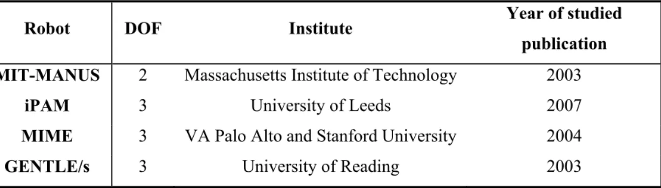
Table 1.1 End-effector type upper-limb rehabilitation state-of-the-art robots
Robot DOF Institute Year of studied
publication MIT-MANUS 2 Massachusetts Institute of Technology 2003
iPAM 3 University of Leeds 2007
MIME 3 VA Palo Alto and Stanford University 2004
GENTLE/s 3 University of Reading 2003
Among some of the end-effector based devices for rehabilitation we can mention: The MIT-MANUS, a 2DOF planar robot to provide physical rehabilitation with extremely low inertia and friction that has presented successful results in tests at the Burke Rehabilitation Hospital (Krebs et al., 2003). The iPAM robotic system, it uses two manipulator-like robots aimed to provide assistive upper-limb therapeutic exercises for post-stroke patients. It has a total of 6DOF and holds patient’s arm at that upper arm and forearm level (Jackson et al., 2007). The MIME system; in it, a robot manipulator (PUMA-560) applies forces to the patient that would normally be provided by a therapist. It restricts hand and wrist movement and the focus of the rehabilitation task is aimed to the forearm using goal-oriented movements. It has also been tested to prove the efficiency of robotic rehabilitation in post-stroke hemiparesis (Lum et al., 2002; Lum, Burgar and Shor, 2004). The GENTLE/s system, it utilizes an active 3DOF haptic master robot attached to the wrist of the patient. It uses tele-presence and virtual reality as the method to provide rehabilitation. This approach encourages the patients to exercise for longer periods of time; it has been tested with stroke patients (Coote et al., 2008; Loureiro et al., 2003). A very important characteristic of this type of robotic devices is that they do not actively support the extremity. Table 1.1 lists the systems described above.
1.1.3 Exoskeleton type upper-limb rehabilitation state of the art robots
Table 1.2 Exoskeleton type upper-limb rehabilitation state-of-the-art robots Robot DOF Institute Year of studied publication ETS-MARSE 7 École de technologie supérieure 2015
CADEN-7 7 University of Washington 2007
ABLE 4 Interactive Robotics
Unit of CEA-LIST 2010
SARCOS 7 University of Southern California 2005
Between some of the exoskeletons devices for rehabilitation we can mention: ETS-MARSE, our project, a 7DOF manipulator-like exoskeleton (Rahman et al., 2015b). It has been developed to the point of having passive, active-assisted and active rehabilitation routines. It remains pending to improve security protocols for the human-machine interaction and to initiate tests with patients to validate the effectiveness of such schemes to provide rehabilitation. The CADEN-7 (Perry, Rosen and Burns, 2007), a 7DOF exoskeleton currently in the third generation of this project. It is controlled by two PCs, one for the low level control (servo control) and the other that calculates the force feedbacks that need to be rendered and applied by the exoskeleton arm, retrieving information from three multi-axis force/torque sensors and can run the virtual environment to be simulated to the user. It can perform different tasks, under four modalities: active and passive mode of rehabilitation, assistive device, haptic device and master device. The ABLE robot, an anthropomorphic upper limb exoskeleton which innovative actuators design allows it to be highly reversible (Garrec, 2010). The 4DOF version was being tested for rehabilitation proposes and the design to create a forearm-wrist module with the remaining 3DOF was under development. The Sarcos Master Arm system (Mistry, Mohajerian and Schaal, 2005), a 7DOF hydraulic model. Besides rehabilitation, it is used to model and study issues of motor control in the human arm by applying forces in the joints as perturbations to learn about the human use of arm redundancy to adapt to this constrains. Table 1.2 lists the systems described above.
1.1.4 Limitations of current approaches
Besides the extensive research and great progress in the field of upper-limb robotic rehabilitation, we still can mention a list of limitations that encompass both hardware design and control algorithms. As the main hardware limitations, we can mention:
Limited degrees of freedom;
Limited range of motion with respect to human range of motion; Complex and robust structures;
Big-sized joint actuators; Weak joint mechanisms;
Inadequate or not-present safety measurements; Lack of adequate gravity compensation;
Complex coupling mechanisms for arm attachment;
Use of wires with intricate routing mechanisms for power transmission. As the main limitations in control approaches we can mention:
Use of linear control techniques as PD and PID;
Very heavy computational demands to handle very complex dynamic models;
Use of simplified models that can introduce lack of robustness and decrease tracking performance;
Chattering when Sliding Mode Control is used.
1.2 Research objectives and methodology
The global objective of this project is to obtain an arm orthosis that can offer passive, active-assistive and active rehabilitation to physically disable people, with full shoulder, elbow and wrist rehabilitation capabilities. To achieve this main objective the ETS-MARSE exoskeleton was used, developed in its mechanical part and first control approaches in a preceding research work of our research group (Rahman, 2012). The focus of the work described in this thesis is to apply a suitable control algorithm for the robot positioning and to develop a sensing interface between the human and the robot that can provide the control of the
exoskeleton by direct command from the person; i.e., to capture the intension of movement of the user to provide active-assisted and active rehabilitation. To that purpose, the following specific objectives with the described methodology were applied during this research project:
1.2.1 Development of the nonlinear control law
Different control techniques were studied. Because the nonlinear nature of the kinematic chain model of a human arm, the resultant model is nonlinear. Nevertheless, approaches as regular and enhanced PID were studied as well as the most used nonlinear control techniques as computed torque control and sliding mode control. A relatively new technique was implemented: Virtual Decomposition Control. A direct comparison between VDC, CTC and SMC was done. Because its advantages, already described, VDC is now used as the main nonlinear control law of the ETS-MARSE.
1.2.2 The sensing interface
This objective involved the analysis, study and implementation of the human-machine interface to obtain the motion intention for the active-assisted and active rehabilitation modes. Force control was implemented by means of the virtual work principle transformation and an admittance function. As the input to the controller, a force sensor was used as well as a nonlinear perturbation observer. Studies in the area of EMG signals were started and the first result towards control directed by means of these signals were implemented and presented. Teleoperation was begun to be studied.
1.2.3 Inverse Kinematics
In order to perform rehabilitation tasks, some trajectories must be provided in Cartesian space. Although the redundancy problem was not solved, an approach to manage some Cartesian trajectories through the Jacobian pseudo-inverse technique was implemented.
1.2.4 Implementation and experimentation
Besides design and simulation with a variety of tools (MATLAB, Mathematica, and LabVIEW), all the control techniques and methods studied in this research work were implemented on the ETS-MARSE.
To summarize the structure of the present work, Figure 1.1 condenses the methodology described above.
Figure 1.1 Methodology
1.3 Originality of the research and contribution
Besides that in this area extensive studies, models, and projects have been done, still remain in front many options to improve and contribute to this technology as well as many problems and areas of opportunity that need to be solved. Particularly, completely satisfactory results that offer passive, active-assisted an active rehabilitation to the 7DOF of the human arm are
not available yet commercially. One of the important contributions of this work is that our robot covers the main seven degrees-of-freedom of the human arm and it presents passive, active-assisted and active rehabilitation schemes. In the particular case of the control, the integration to the ETS-MARSE of the Virtual Decomposition Control, a relatively new approach that showed advantages over other classic techniques, is an important aspect of this research.
In general, the results contribute in an area of constant growth, permitting to complement the existing knowledge in the field. Finally, the most important contribution will be to help people with physical disability to assist the rehabilitation process, helping them to return to a productive and more independent life, improving in a significant way its quality of life.
CHAPTER 2
VIRTUAL DECOMPOSITION CONTROL OF AN EXOSKELETON ROBOT ARM Cristóbal Ochoa Luna1, Mohammad Habibur Rahman1, 2, Maarouf Saad1, Philippe
Archambault2, 3, and Wen-Hong Zhu4
1Department of Electrical Engineering, École de technologie supérieure,
1100 Notre-Dame West, Montreal, Quebec (H3C 1K3) Canada.
2School of Physical & Occupational Therapy, McGill University,
3654 Prom Sir-William-Osler, Montréal, Québec (H3G 1Y5) Canada.
3Centre for Interdisciplinary Research in Rehabilitation (CRIR),
2275 Laurier Avenue East, Montréal, Quebec (H2H 2N8) Canada.
4Space Exploration, Canadian Space Agency,
6767 Route de l'Aéroport, Longueuil (St-Hubert), Quebec (J3Y 8Y9) Canada.
This paper was published in Robotica on October 14, 2014
Abstract:
Exoskeleton robots, which can be worn on human limbs to improve or to rehabilitate their function, are currently of great importance. When these robots are used in rehabilitation, one aspect that must be fulfilled is their capacity to adapt to different patients without significantly varying their performance. This paper describes the application of a relatively new control technique called Virtual Decomposition Control (VDC) to a seven degrees-of-freedom (DOF) exoskeleton robot arm, named ETS-MARSE. The VDC approach mainly involves decomposing complex systems into subsystems, and using the resulting simpler dynamics to conduct control computation, while strictly ensuring global stability and having the subsystem dynamics interactions rigorously managed and maintained by means of virtual power flow. This approach is used to deal with different masses, joint stiffness and biomechanical variations of diverse subjects, allowing the control technique to naturally adapt to the variances involved and to maintain a successful control task. The results
obtained in real time on a 7DOF exoskeleton robot arm show the effectiveness of the approach.
Keywords: Exoskeleton robot, Virtual Decomposition Control, passive rehabilitation, active rehabilitation, upper-limb impairment, dynamic variations.
2.1 Introduction
Orthotic robots, or exoskeletons, mimic and adapt to the structure of an injured limb to improve, re-establish or complete some of its functionality (Pons, 2008). Following occupational and sport injuries, traumas, geriatric disorders (Department of Economic and Social Affairs, 2013) and strokes (Mackay and Mensah, 2004), etc., diverse types of physiological complications can arise, possibly leading to social, labour and personal limitations, and consequently decreasing the quality of life of a large number of individuals. One of the symptoms most often diagnosed as a result of a stroke is the loss of function on one side of the body. The main treatment for this is rehabilitation, which requires hours of highly skilled and extensive procedures. The number of people qualified to provide such support is hardly enough to treat all patients affected. Rehabilitation can be supplemented with the use of robots, especially wearable (orthotic or prosthetic) robots (Garrec et al., 2008; Nef et al., 2009; Rahman et al., 2012c). These robots can help people by reducing the impacts of their disabilities and by significantly improving their quality of life.
Passive arm movement therapy is a form of treatment used among patients who are unable to actively move their arms throughout their complete range of motion, following a neurological insult, such as a stroke, which can lead to weakness or paralysis. In passive rehabilitation, the affected limb is moved by external forces (therapist or robot) while the patient relaxes. Active rehabilitation for its part focuses on long-term results; it encourages subjects to move their arms by themselves in order to build muscle strength and flexibility. These issues must therefore be properly addressed in rehabilitation robotics. In the area of upper limb rehabilitation, which was initialized in the middle of the twentieth century (Van
der Loos and Reinkensmeyer, 2008), it was not until very recently that truly functional experimental implementations were obtained with the full capabilities of the whole arm (shoulder, elbow and wrist) (Perry and Rosen, 2006; Tsagarakis, Caldwell and Medrano-Cerda, 1999). Different studies have shown that the use of robotic tools in rehabilitation provides intensive therapy that leads to measurable functional gains (Eschweiler et al., 2014; Lo and Xie, 2012; Norouzi-Gheidari, Archambault and Fung, 2012; Sarakoglou et al., 2007). To that end, work in our laboratory has led to the development of a seven DOF exoskeleton robot to ultimately assist patients with shoulder (3DOF), elbow (1DOF), and wrist (3DOF) movements (Rahman et al., 2015b). The primary objective of this research is to develop a robotic device that can offer passive and active rehabilitation, as well as daily assistance of the upper limbs, to physically disabled people.
A wide range of approaches have been proposed to control rehabilitation robots, ranging from simple PD controllers to nonlinear techniques such as Computed Torque Control (CTC) and Neuro-Fuzzy controllers. Some attractive combined approaches, such as an adaptive Fuzzy controller based on Sliding Mode Control (SMC), for example, was presented by Sun et al (Sun, Sun and Feng, 1999), and seems to be able to deal with the inherent chattering of the SMC, subject to model uncertainties and external disturbances. A combination of adaptive and robust control (Uzmay and Burkan, 2002) merges the advantages of both control laws, eliminating the disadvantage of adaptive controllers in transient behaviour and suppressing the steady-state error. Furthermore, a CTC with Fuzzy Control (Song et al., 2005) provides satisfactory results, subject to manipulator-structured and unstructured uncertainties. An adaptive control with an Artificial Neural Network was presented by Ciliz (Ciliz, 2005) for dealing with frictional uncertainties, which are highly difficult to model. Some other approaches use robust adaptive control that indicate an interesting way of dealing with system uncertainties and external disturbances (Li et al., 2008; Zhijun et al., 2008). However, some fundamental problems are yet to be solved.
In CTC, the main concern is that the control only shows moderate performance improvement when the dynamical model is not exactly known, and this is true even for robots with
relatively small numbers of DOF, such as 4DOF orthosis (Brackbill et al., 2009) for example. Neuro-fuzzy controllers are highly complex, and use different sets of rules and layers involving switching in different regions of operation. This is true even for 3DOF arm exoskeletons (Rahman et al., 2006). In most of the above-mentioned approaches (Ciliz, 2005; Li et al., 2008; Song et al., 2005; Sun, Sun and Feng, 1999; Uzmay and Burkan, 2002; Zhijun et al., 2008), the results are mainly restricted to simulations (i.e., a 2DOF manipulator (Sun, Sun and Feng, 1999), a two-link planar robot (Uzmay and Burkan, 2002) and a two-link elbow planar manipulator (Song et al., 2005)) or implementation on simple robots (i.e., successfully tested on a two-link SCARA type direct drive arm (Ciliz, 2005)).
As can be seen, two specific problems need to be considered together in exoskeleton research: the high number of degrees-of-freedom and the system variability (biomechanical and physiological). For these reasons, a novel application of the Virtual Decomposition Control (VDC) technique is introduced in this paper for the control of exoskeleton robots, in order to address two important issues: a) to facilitate the implementation of a high degree-of-freedom robot (7DOF in this case), and b) to cope with the changes in the dynamics of the robot-human system, due to the biomechanical and physiological characteristics of different patients. As robots become more complex, the complexity of the control task increases as well. Indeed, the complexity of the computation of robot dynamics is proportional to the fourth power of the number of degrees-of-freedom in Lagrangian dynamics (Zhu, Piedboeuf and Gonthier, 2006). This research deals with a complex 7DOF robot. The VDC approach allows us to break the system down into subsystems with relatively simpler dynamics and to apply the control directly over those subsystems. The Virtual Decomposition Control uses the dynamics of subsystems (rigid links and joints) to conduct control design, while rigorously maintaining the L2 and L∞ stability of the entire robotic system (Zhu and De
Schutter, 2002). This virtual decomposition yields simpler dynamic equations, both in their formulation and implementation. Proceeding as such maintains the complexity of the dynamics of the subsystems constant, meaning that as more and more DOF are added to the robot, the complexity of the total system increases linearly. With the system broken down into simpler subsystems, the VDC handles the dynamic interactions among subsystems
mathematically through the definition of virtual power flows. Thus, even with the subsystem decomposition, the highly nonlinear dynamics of the robotic system are not decoupled, thereby maintaining the control and stability of the entire system.
An additional advantage of the VDC is its ability to manage, through its parameter adaptation, the inherent variability that is present in human dynamics. In addition to the imperfect knowledge of the dynamics of the body structures, different individuals will display differences in body mass, weight distribution, limb length, etc. Moreover, muscular and neurological conditions can change the visco-elastic properties of muscles and joints. For controllers that need to know the dynamical model of the system (e.g., CTC), variations in all these parameters could have a negative impact on the performance of the robot. In our previous research (Rahman et al., 2012b), SMC was implemented for dynamic trajectory tracking corresponding to typical passive rehabilitation exercises. Though SMC performed well, it also showed some limitations in dealing with different subjects. The adaptive characteristics of the VDC overcome this limitation by dealing with biomechanical and physiological variations, providing a better and constant performance of the exercises.
The original contribution of this paper is the application of the VDC to address the issue of dynamic variability, due to individual differences, in order to obtain constant performance by a rehabilitation exoskeleton arm. As well, the simplification of the control task of these multi-articulated robots, through the virtual decomposition process and the use of virtual stability and virtual power flows, allows a simpler computation for systems with high numbers of degrees-of-freedom. The experiments were carried out on different healthy subjects with the ETS-MARSE exoskeleton robot, designed by our research team.
This paper is organized as follows: section 2.2 presents a brief description of the robot and its characteristics. Section 2.3 lays out a detailed presentation of the control development. Finally, in section 2.4, the implementation of the control and experiments executed are explained and the results are presented and discussed, followed in section 2.5 by the conclusions of the work.
2.2 Characteristics of the Motion Assistive Robotic Exoskeleton for Superior Extremity
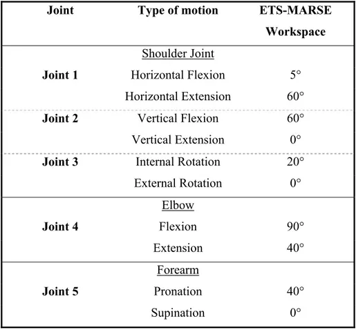
The wearable upper-limb exoskeleton robot, named “Motion Assistive Robotic Exoskeleton for Superior Extremity” (ETS-MARSE) has 7DOF, and was designed to correspond to the natural range of movement of the upper extremity of the human body. It is comprised of a shoulder motion support part (which assists in horizontal flexion/extension (Figure 2.1a), vertical flexion/extension (Figure 2.1b), and internal/external rotation (Figure 2.1c) of the shoulder), an elbow motion support part (Figure 2.1d) for elbow flexion/extension, a forearm motion support part which is responsible for forearm pronation/supination (Figure 2.1e), and a wrist motion support part (for flexion/extension (Figure 2.1f) and radial/ulnar deviation (Figure 2.1g) of the wrist).
Figure 2.1 Joint range of motion of ETS-MARSE
(a) shoulder joint: horizontal flexion/extension; (b) shoulder joint: vertical flexion/extension; (c) shoulder joint: internal/external rotation; (d) elbow flexion/extension; (e) forearm pronation/supination; (f) wrist
The exoskeleton is an open kinematic chain, manipulator-like robot, with seven revolute DOF ( = 7). The kinematics of any robot can be described with four parameters per joint, two describing the joint, and two for its connection with the adjacent joint. One parameter is the joint variable (angle if revolute, distance if prismatic), while the other three are constants (an angle or a distance, opposite of the joint variable and the angle and distance from joint to joint). This convention is known as the Denavit-Hartenberg notation; it has two variations, the original and the modified. As described in Craig (Craig, 2005), with the frames attached to the robot as shown in Figure 2.2, the modified Denavit-Hartenberg parameters are obtained and summarized in Table 2.1.
Figure 2.2 7DOF Exoskeleton robot arm
Frame {0} represents the base frame; frame {1}: shoulder horizontal flexion/extension; frame {2}: shoulder vertical flexion/extension; frame {3}: shoulder internal/external rotation; frame {4}: elbow flexion/extension; frame {5}: forearm pronation/supination; frame {6}: wrist flexion/extension and frame {7}: wrist radial/ulnar deviation. Axes shown are in positive direction
Table 2.1 ETS-MARSE Modified Denavit-HartenbergParameters i αi-1 ai-1 di θi 1 0° 0 d1 θ1 2 -90° 0 0 θ2 3 90° 0 d2 θ3 4 -90° 0 0 θ4 5 90° 0 d5 θ5 6 -90° 0 0 θ6-90° 7 -90° 0 0 θ7
2.3 Analysis of the ETS-MARSE robot with Virtual Decomposition Control (Zhu et al., 1997)
The first step in VDC analysis is to perform the virtual decomposition of the robot; in this case, the exoskeleton is a single open chain. This decomposition allows us to base control directly on subsystem dynamics, allowing it to remain relatively simple, i.e., proportional to the number of subsystems. Decomposition is done by placing virtual cutting points separating each joint and link of the system into a subsystem. Although the robot or the human arm does not have seven links (see Figure 2.2), this is a virtual decomposition, and is performed as such to express the system in its most basic operative units. This is a basic approach of VDC to maintain the equations of the system at their most simple expressions for computational handling; another advantage is that if a change is made to any actuator, only the dynamics of that joint will change, not the rest of the system. The result of the system decomposition is illustrated in Figure 2.3: it yielded a decomposition into fourteen subsystems, with the virtual cutting points represented by vertical dotted lines, linked to their respective frames by horizontal dotted lines.
Figure 2.3 Virtual decomposition into 14 subsystems
2.3.1 Kinematics
From the resulting modified Denavit-Hartenberg parameters for the decomposition shown in Figure 2.3, the homogeneous transform matrices of the system are obtained. Using them, it is necessary to calculate the force/moment transformation matrices between any consecutive { } frames for = 1, … , 6 (see Figure 2.3) as follows:
= ×
( ×) ∈ ℝ ×
(2.1)
where represents the rotation matrix from frame to frame and the vector pointing from to frame , and:
( ×) =
0 − (3) (2)
(3) 0 − (1)
− (2) (1) 0
(2.2)
where ( ) represents the th term of the vector.
The next step is to calculate , the linear/angular velocity vectors of the { } frames for = 1, … ,7 as follows:
= ∈ ℝ (2.3)
where is the linear velocity vector and is the angular velocity vector of the corresponding frame. Defining each joint position (angle) as to and using the previous linear/angular velocity vectors in (2.3), the augmented velocity vector is formed as follows:
= [ ⋯ ⋯ ] (2.4)
Factorizing the joint velocity vector = [ ⋯ ] in (2.4), we obtain:
= (2.5)
where is the VDC Jacobian matrix of the system:
= 0 ⋯ 0 ⋱ ⋮ ⋮ ⋱ ⋱ 0 … (2.6)
where = [0 0 0 0 0 1] , represents the 7× 7 identity matrix and 0 is a six-element zero vector. Note that the dimension of is 49 × 7; the aforementioned identity matrix and a block of 6 × 7 for each one of the seven degrees-of-freedom of the robot.
Finally, for the kinematics, it is necessary to calculate the required velocities, which are functions of the control requirements. They incorporate terms that allow the tracking of a control objective to the desired velocities obtained from the trajectory generator. In this case, position control is used such that the position is incorporated into the vector of required velocities.
= + ( − ) (2.7)
where = [ ⋯ ] is a 7 × 1 reference velocity vector, = [ ⋯ ] is the 7 × 1 desired velocity vector, > 0 is a control parameter, = [ ⋯ ] is the 7 × 1 desired position vector and = [ ⋯ ] the 7 × 1 position vector. From (2.6) and (2.7), the 49 × 1 augmented required velocity vector is obtained as follows:
= (2.8)
From (2.4), it can be established that:
= [ ⋯ ⋯ ] (2.9)
2.3.2 Dynamics
For the simulation, the dynamics of the robot was obtained using the Newton-Euler approach (Craig, 2005). To apply the VDC approach and to obtain the inverse dynamics that takes part in the control of the robot, it was necessary to calculate the required force/moment vectors for the links, , and then the net torques required by the joints, ∗ .
From the general formulation of a rigid body dynamics, in which one frame { } is used as the reference to express the dynamics, and another frame { } is assumed to be located at the centre of mass, the rigid body dynamics can be expressed as:
( ) + ( ) + = ∗ (2.10)
where (Zhu et al., 1997):
= − ( ×) ( ×) − ( ×) (2.11) ( ) = ( ×) − ( ×)( ×) ( ×)( ×) ( ×) + ( ×) − ( ×)( ×)( ×) (2.12) = ( ×) (2.13)
where ∈ ℝ is the mass of the rigid body, is a 3 × 3 identity matrix, = ( ) is time invariant, ( )∈ ℝ × denotes the moment of inertia
matrix around the centre of mass, ∈ ℝ × is the rotation matrix from frame to the
inertial frame, r ∈ ℝ is the vector pointing from frame to frame , ∈ ℝ is the angular velocity vector, = [0 0 9.81] ∈ ℝ and ( ×) and ( ×) are defined as in relation (2.2).
Substituting from (2.10) the dynamic model velocity vector by the required velocity
vector ∈ ℝ defined in (2.9), the following equation is defined:
where ∈ ℝ × is a regressor matrix composed of elements of / ( ) ∈ ℝ , the
velocity vectors ∈ ℝ and ∈ ℝ and terms from the vector of gravity propagation, and ∈ ℝ is the vector composed of the mass of the link, the elements of the vector pointing from the origin of the reference frame of the link toward its mass centre, and elements of the inertia tensor of the body. The exact representation of each element of and
is given in Appendix A.
By means of the linear parameterization expressed above in (2.14), the first step for the link dynamics is to obtain the required net force/moment vectors with the following equation:
∗ = + ( − ) (2.15)
for = 1, … ,7 where ∗ are the required net force/moment vectors, is a symmetric
positive-definite gain matrix, and are the velocities defined in (2.4) and (2.9), and ∈ ℝ is the estimated parameter vector. The estimation of the parameters in is defined as follows (Zhu et al., 2013):
= ( ), , ( ), ( ), (2.16)
for = 1, … ,7 and = 1, … ,13, where represents the th parameter of the th link, ( ) ∈ ℝ is a scalar variable defined as the th element in:
= ( − ) (2.17)
is the parameter update gain, ( ) and ( ) are the lower and upper bounds of respectively, and the projection function is a differentiable scalar function (Zhu and De Schutter, 1999) defined for ≥ 0 such that its time derivative is governed by:
with:
= 00 1
≤ ( ) ≥ ( ) ( ) ≤ 0 ( ) ≥ 0 ℎ
Once this step is complete, the required force/moment vectors at the cutting points are obtained as follows:
= ∗
= ∗+
(2.19)
for = 6, … ,1. The next step is the calculation of the dynamics of the joints. For = 1, … ,7 in (2.20) to (2.24), the following vector and parameter vector are defined:
= [ ( ) 1] (2.20)
= [ ] (2.21)
where the sub-index in the vectors is used to differentiate joint variables from the link variables introduced in (2.15), is the equivalent mass or moment of inertia, > 0 denotes the Coulomb friction coefficient, > 0 is the viscous friction coefficient and denotes an offset that accommodates asymmetric Coulomb frictions. The adaptation of the parameters defined in (2.21) is calculated as:
= ( ), , ( ), ( ), (2.22)
for = 1, … ,7 and = 1, … ,4, where represents the th parameter of the th joint, ( ) ∈ ℝ is a scalar variable defined as the th element in:
is the parameter update gain, ( ) and ( ) are the lower and upper bounds of respectively, and the projection function is a differentiable scalar function defined in (2.18).
Finally, the net torque for the joint ∗ is obtained as follows:
∗ = + ( − ) (2.24)
where ∗ is the net torque of the joint, denotes a feedback gain and ∈ ℝ defined in (2.22) denotes the estimate of ∈ ℝ defined in (2.21).
2.3.3 Control
To develop the control of the entire system, the torques resulting from the link and joint analysis are combined. First, it is necessary to extract the torque of the link force/moment vector as follows:
= (2.25)
for = 1, … ,7. With = [0 0 0 0 0 1] that was defined earlier, the control torque is designed as:
= ∗ + (2.26)
for = 1, … ,7. The flow diagram with the calculations needed in the VDC technique is shown in Figure 2.4.
Figure 2.4 Block diagram of the system
(with the equations used in each step in the parentheses)
Associating (2.26) with the traditional dynamic equation of a manipulator:
= ( ) + , + ( ) + ( , ) (2.27)
where ( ) is the manipulator’s × mass matrix, , the × 1 Coriolis and centrifugal terms vector, ( ) the × 1 gravity terms vector and ( , ) the × 1 torque friction vector. It is clear that in the case of VDC, the parameter adaptation that is defined in (2.15) and (2.24) from equations (2.10) to (2.14) for the rigid links and (2.20) to (2.21) for the joints, will incorporate not only the mass, inertia (moments and products) and centre of mass parameters of the links, and the moment of inertia and friction for the joints of the robot, but also the uncertainties and the disturbances introduced by the subject, which are not modelled. For example, the mass of the human arm (different from subject to subject) will be combined with the links’ mass; changes or displacements in the position of the arm of the subject, combined with changes in position of the centre of mass; and friction of the joints, combined with constraints of the movement caused by the subject’s limitations, such as difficulty to move due to spasticity or altered muscle tone.
2.3.4 Stability Analysis
Given the dynamics expressed in relation (2.27) and the control design given in (2.19) and (2.24), combined as indicated in (2.25) and (2.26), the asymptotic stability is ensured if the position and velocity errors converge asymptotically to zero:
→ ‖ ( ) − ( )‖ → 0 (2.28)
→ ‖ ( ) − ( )‖ → 0 (2.29)
with q and q vectors defined in (2.4) and (2.5) and and vectors defined in (2.7).
Using the Lyapunov approach, a non-negative candidate function is defined and then it is shown that the variation is a decreasing function. As explained in the previous section, the system dynamics has two parts. The first represents the link dynamics given by:
+ + = ∗ = 1 … (2.30)
And the second, given in relation (2.31), represents the joint dynamics, characterized by the torque resultant from the moment of inertia plus the torque from the Coulomb friction:
+ ( ) = ∗ = 1 … (2.31)
Therefore, considering the Lyapunov candidate function for the entire robot as:
= + (2.32)
where represents the non-negative Lyapunov candidate function related to the link dynamics and is the non-negative Lyapunov candidate function related to the joint
dynamics. Combined with the control equation (2.15) and the parameter adaptation defined in (2.16) and (2.17), is defined as follows:
=1
2 − − +
1 2
( − ) (2.33)
The non-negative Lyapunov candidate function related to can be defined as follows:
=1
2 ( − ) +
1 2
( − ) (2.34)
The derivative of the Lyapunov candidate function (2.32) is given as:
= + (2.35)
Before showing that relation (2.35) is always decreasing, it is necessary to define the virtual power flows as the inner product of the linear/angular velocity vector error and the force/moment vector error (Zhu and Lamarche, 2007; Zhu et al., 1997). With respect to a frame A:
≝ ( − ) ( − ) (2.36)
virtual power flows characterize the dynamic interaction between subsystems at its cutting points. They are analogue to power flows within a rigid body, but instead of being the inner product of a velocity vector and a force vector, they are the inner product of a velocity vector error and a force vector error. With definition (2.36), it follows that:
≤ − − − + − ∗− ∗
Considering (2.36) and the force/moment transformation matrices defined in (2.1) to transform the velocities expressed in (2.3) and the required velocities expressed in (2.9), and with the net force/moment and required net force/moment vectors (2.19), this yields:
− ∗− ∗ = − (2.38)
where the terms on the right side of (2.38) represent the virtual power flows at the two cutting points of each link.
can be written (Zhu et al., 1997) as:
≤ − ( − ) − + (2.39)
Considering an open chain structure, as is the case in this paper, and with = 0 and = 0, the total virtual power flows gives:
− = 0 (2.40)
Therefore, relationship (2.37) becomes:
≤ − − − (2.41)
and the function becomes:
≤ − ( − ) (2.42)
Finally, from relationships (2.41) and (2.42), and given positive gains and , the derivative of the Lyapunov function , given in (2.43), is always decreasing.