HAL Id: hal-02914515
https://hal.archives-ouvertes.fr/hal-02914515
Submitted on 20 Aug 2020HAL is a multi-disciplinary open access
archive for the deposit and dissemination of sci-entific research documents, whether they are pub-lished or not. The documents may come from teaching and research institutions in France or abroad, or from public or private research centers.
L’archive ouverte pluridisciplinaire HAL, est destinée au dépôt et à la diffusion de documents scientifiques de niveau recherche, publiés ou non, émanant des établissements d’enseignement et de recherche français ou étrangers, des laboratoires publics ou privés.
The Injection and Chopper-Based System at Arronax
C70XP Cyclotron
Freddy Poirier, Guillaume Blain, Francois Bulteau-Harel, Sophie Chiavassa,
Gregory Delpon, Teddy Durand, Massoud Fattahi, Xavier Goiziou, Ferid
Haddad, Charbel Koumeir, et al.
To cite this version:
Freddy Poirier, Guillaume Blain, Francois Bulteau-Harel, Sophie Chiavassa, Gregory Delpon, et al.. The Injection and Chopper-Based System at Arronax C70XP Cyclotron. 22nd International Conference on Cyclotrons and their Applications (CYC2019), Sep 2019, Cape Town, South Africa. pp.TUP006, �10.18429/JACoW-Cyclotrons2019-TUP006�. �hal-02914515�
THE INJECTION AND CHOPPER-BASED SYSTEM AT ARRONAX C70XP
CYCLOTRON
F. Poirier
†,1, F. Bulteau-harel, T. Durand, X. Goiziou, C. Koumeir, H. Trichet, A. Sengar
ARRONAX, Saint-Herblain, France
G. Blain, M. Fattahi, F. Haddad, J. Vandenborre, IN2P3/SUBATECH, Nantes, France
S. Chiavassa, G. Delpon, ICO, Saint-Herblain, France
1
also at CNRS - DR17, Rennes, France
Abstract
The multi-particle cyclotron of the Arronax Public Inter-est Group (GIP) is used to perform irradiation up to hun-dreds of µA on various experiments and targets. To support low and high average intensity usage and adapt the beam time structure required for high peak intensity operation and experiments such as pulsed experiments studies, it has been devised a pulsing system in the injection of the cyclo-tron. This system combines the use of a chopper, low fre-quency switch, and a control system based on the new ex-tended EPICS network. This paper details the pulsing sys-tem adopted at Arronax, updates and results for various in-tensity experimental studies performed with alpha and pro-ton beams. Updated work on the simulation of the injection is also shown, specifically towards high intensity future ir-radiation.
INTRODUCTION
The Arronax cyclotron has been performing irradiation for 9 years delivering beams with intensities ranging over several orders of magnitudes. Typically for experimental studies, the average intensity is below one µA, while high-est intensity irradiation for radio-isotope production can be at least up to 350 µA for proton and 20 µA for alpha in a single beamline. The cyclotron provides bunches inter-spaced by 32.84 ns (RF frequency = 30.45 MHz) translat-ing into 7.8x10⁷ particles per bunch for protons. To
con-form to the needs of the users for the range of beam inten-sities, several techniques are being employed based on the tuning of the source and the various magnet elements throughout the accelerator and specifically in the injection.
Additionally, a new chopper-based system located in the injection has been added and its characteristics and impact on the beam are being investigated in order to extend its use for high intensity operations.
CONCEPT AND LAYOUT
The pulsing chopper based system is designed to provide a variable number of trains of bunches to users from an in-itial continuous bunch structure, typical of cyclotrons. The present prototype design and functioning system allows thus to modify train duration and repetition. It is detailed in [1] as well as the first results at low intensity and the monitoring system that is being used.
The chopper system allows to bend away bunches at low energy (~40 keV for protons and 20 keV for other parti-cles) in the injection. Its main components are:
Two parallel copper plates within the beampipe A High Voltage (HV) switch (Behlke type) located
outside the beampipe and closed (<30 cm) to the plates.
Control electronics and a Raspberry Pi3 server within an EPICS network environment.
A Control System Studio-based (CSS) interface with a simple visualisation terminal.
At the present time, the CSS interface gives operators the possibilities to manually modify the duration, repetition and number of trains that the experimenters require.
The control electronics located outside the cyclotron vault serves as a counting board for the number of RF buckets, a trigger for the desired state (closed/open) of the switch and a mirror trigger for experimental use.
When the HV switch is closed, 3.3 kV is applied to the plates, ejecting bunches to the injection beampipe wall.
EXPECTED CAPACITIES
At low intensity, the resulting trains have been checked using a light detector and have indicated rise and fall times of the order of a few microseconds [1]. An extended scan over the repetition frequency and train duration has been performed and has shown the potential usage from 10 Hz to 50 kHz with trains from 164 ns up to the continuous case.
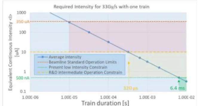
A relatively good linearity has been obtained for dura-tion above a few hundreds of ns and with repetidura-tion below 10 kHz. With this configuration at Arronax, Fig. 1 illus-trates the average intensity <I> required for protons to reach, in a single train, dosimetry level of 33 Gy/s at the plateau before the Bragg peak as a function of the train du-ration. The figure indicates that a 6.4 ms train at <I> = 500 nA can reach the considered dosimetry level, and 320 µs at <I> = 10 µA.
Figure 1: Avg. intensity as a function of the train duration to reach a dosimetry of 33 Gy/s at the Bragg peak plateau.
___________________________________________ † [email protected]
22nd Int. Conf. on Cyclotrons and their Applications Cyclotrons2019, Cape Town, South Africa JACoW Publishing ISBN:978-3-95450-205-9 doi:10.18429/JACoW-Cyclotrons2019-TUP006
04 Operation and Upgrades
TUP006 159 Content from this w ork ma y be used under the ter ms of the CC B Y 3.0 licence ( © 2019). An y dis tr ibution of this w ork mus t maintain attr ibution to the author(s), title of the w ork, publisher , and DOI
INTENSITY STUDIES
A study of the use of the chopper is performed in com-parison to the standard usage.
Low Intensity Tune
For low intensity, the arc source is minimised such that the beam remains stable, e.g. not too low. To reach very low and ultra-low intensity of the order of a few pA, sole-noids in the injection are detuned. Three solesole-noids, of gla-ser-type, i.e. with a bell-shaped z-axial field distribution, are used: The source solenoid (SG) located downstream the source; the injection glaser (IG); and upstream the central region of the cyclotron, the cyclotron solenoid (CG). Fig-ure 2 shows the impact of the intensity of the detuning of each solenoid. SG has the most drastic effect and is thus primarily used to decrease intensity to very low levels. Us-ing this intensity degradation, the method has also shown that particles were lost mainly prior to acceleration below 1 MeV. It benefits operation ease, as only one knob is used.
Figure 2: Intensity on the probe at 150 mm inside the cyclotron according to the settings of the three solenoids at various arc source.
High Intensity Tune
Traditionally for operations at high intensity the arc source is tuned to increase the beam intensity. All magnet elements are modified in accordance to allow maximum transmission from the injection faraday cup down to the irradiation station or experiment area.
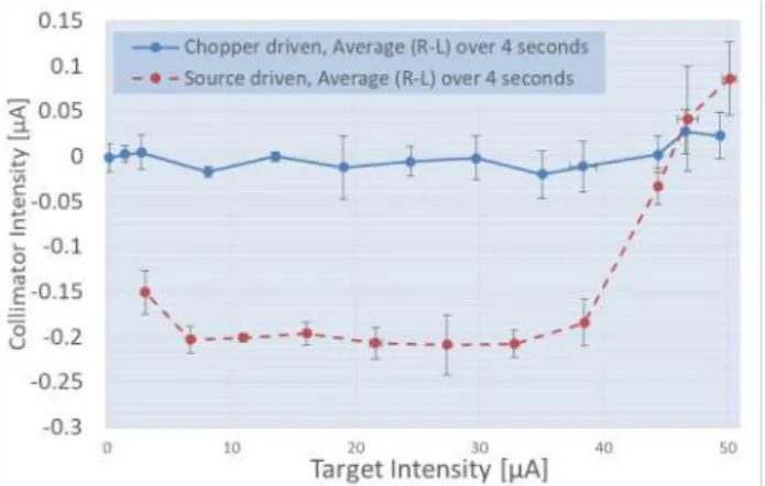
The chopper-based system has been used to check its compatibility with high intensity runs (~50 µA on target). For the tests, the system was fixed at a 100 Hz repetition (or 10 ms time length) and a train duration from 0.5 ms up to 9.995 ms. Results are presented below: Figure 3 shows the linearity of the intensity on target using only this sys-tem and Fig. 4 depicts the beam geometry as given by a 4-independent fingers collimator. The difference of the right and left fingers electrical deposit (R-L) is here given, and represents in the case of a symmetric beam, the position of the transverse beam. Both techniques to lower down the average intensity, with the chopper or the source only, are used, to check the beam position. Without further retuning of any magnets, the chopper-based technique points to a better global stable beam when intensity modification oc-curs. This is also the case when the intensity is dropped by unwanted events such as breakdowns.
Figure 3: Target intensity up to 45 µA as a function of the train duration as driven by the injection chopper system.
Figure 4: Average horizontal beam position at collimator for both techniques, i.e. source and pulsed-chopper driven, vs the intensity on target. 3×Standard Deviation are used for vertical error bars.
Discussion
First, the techniques based on the chopper has shown that it can be used with any particles and is applicable to any of the 8 beamlines of Arronax.
Second, the chopper can be used at high intensity, and suggest a certain reliability for short runs within the Arronax environment. For present test-runs, the integrated dose, measured with a Landauer neutron dosimeter on the switch, reached more than 110 mSv.
Taking into account the rise time of chopper in terms of the measured end-of-line intensity (<3 µs), the system shows it could potentially be integrated in the machine protection scheme. The results point that use of the switch to lower down the intensity when a breakdown occurs could provide a faster and more stable beam. This has to be reviewed in light of the difficulty to apply the right algorithm to lower down the beam intensity and then increase it again after breakdowns occurred downstream the chopper.
INJECTION STUDIES AND SIMULATION
Previous experimental studies have revealed that parti-cles can still be accelerated depending on the settings of SG, mostly when defocalisation occurs with the solenoid being at low settings. This has asked to check the intensity
22nd Int. Conf. on Cyclotrons and their Applications Cyclotrons2019, Cape Town, South Africa JACoW Publishing ISBN:978-3-95450-205-9 doi:10.18429/JACoW-Cyclotrons2019-TUP006 TUP006 160 Content from this w ork ma y be used under the ter ms of the CC B Y 3.0 licence ( © 2019). An y dis tr ibution of this w ork mus t maintain attr ibution to the author(s), title of the w ork, publisher , and DOI
prior to fix the settings of the solenoid when the chopper is used.
To verify various operational scenarios and study several potential optimisations, simulations of the injection are on-going.
Injection Simulation
G4Beamline, a particle tracking simulation program based on Geant4, is used at Arronax to perform detailed simulation that requires field and particle matter interaction impact for the various accelerator parts [2, 3].
A simplified model of the injection has been gathered and includes the field from all main magnetic elements and also the plates of the chopper-based system.
Magnet Field Construction
The models of the magnetic fields are based at the present time on approximated calculation and, when available, on the measurements performed by the magnets provider, SigmaPhi. Simulated field maps are constructed by applying a simple differential minimisation algorithm with the experimental measurements for the quadrupoles, solenoids and dipoles. This helped to perform integration to a more global model of the injection. Figure 5 shows the entire injection modelled in G4Beamline.
Figure 5: The overall G4Beamline model of the injection.
Simulation Input and Tune
From the experimental resulting field, fringe factors (= 0.3) as defined in G4beamline have been applied. Several emittances with a round beam at the exit of the source have been studied. For the present studies a beam of transverse dimension σx,y = 9.9 mm, σx’,y’ = 0.0018 (Here
δx,y/δz slope) has been used.
Simulation Results
The scenario with a beam approximately centered along the vertical z-axis has been chosen. This needed to kick the beam upstream the 90°-dipole with the steerer. With this scenario, the core of the beam is going between the chopper plates. Virtual Detectors (VD) located along the z-axis serves as ideal beam monitors. The results are depicted in Fig. 6 concerning the two extreme operation modes of the
chopper: Stop mode, the chopper is kept at 3.3 kV, and continuous mode, the chopper is at 0 kV.
Similar to the experiments reported in [1], it can be observed that in the stop mode of this scenario and without any collimators, several particles can pass through. A collimator, upstream the chopper plates, helps to lower down the quantity of particles in the stop mode.
Figure 6: Number of particles on VD vs the solenoid setpoints for both extreme modes and impact of a 22 mm aperture collimator.
Experimental tests with a collimator are foreseen though still several simulation scenarios have to tackle various hy-pothesis on the beam.
CONCLUSION
Within the Arronax injection section, a chopper-based pulsed system has been added and is fully functional for low and high intensity beam. It helps to provide a temporally defined train of bunches, and if chosen to drive the average intensity, can contribute to further stabilise the beam. Though, optimisation for potential high intensity standard irradiation is needed.
A first model of the injection has also been built and already helps to explore various scenarios in view of the decision making towards optimisation. Further realistic field models have to be implemented.
ACKNOWLEDGEMENTS
This work has been, in part, supported by grants from the Région Pays de la Loire and the French National Agency for Research called "Investissements d'Avenir", Arronax-Plus n°ANR-11-EQPX-0004, IRON n°ANR-11-LABX-18-01 and Next n°ANR-16-IDEX-0007 and by Institut de Cancérologie de l’Ouest (internal call Emergence 2018).
REFERENCES
[1] F. Poirier et al., “The pulsing chopper-based system of the Arronax C70XP cyclotron”, in Proc. IPAC’19, Melbourne, Australia, June 2019. doi:10.18429/JACoW-IPAC2019-TUPTS008
[2] F. Poirier et al., “The C70 ARRONAX and beam lines status”, in Proc. IPAC'11, San Sebastian, Spain, Sep. 2011, paper WEPS069, pp. 2661-2663.
[3] A. Sengar et al., “Development of a beam loss monitor and transverse beam dynamics studies at ARRONAX C70XP cyclotron”, in Proc. IPAC’19, Melbourne, Australia, June 2019. doi:10.18429/JACoW-IPAC2019-WEPGW006
22nd Int. Conf. on Cyclotrons and their Applications Cyclotrons2019, Cape Town, South Africa JACoW Publishing ISBN:978-3-95450-205-9 doi:10.18429/JACoW-Cyclotrons2019-TUP006
04 Operation and Upgrades
TUP006 161 Content from this w ork ma y be used under the ter ms of the CC B Y 3.0 licence ( © 2019). An y dis tr ibution of this w ork mus t maintain attr ibution to the author(s), title of the w ork, publisher , and DOI