HAL Id: tel-02003027
https://pastel.archives-ouvertes.fr/tel-02003027
Submitted on 1 Feb 2019HAL is a multi-disciplinary open access archive for the deposit and dissemination of sci-entific research documents, whether they are pub-lished or not. The documents may come from teaching and research institutions in France or abroad, or from public or private research centers.
L’archive ouverte pluridisciplinaire HAL, est destinée au dépôt et à la diffusion de documents scientifiques de niveau recherche, publiés ou non, émanant des établissements d’enseignement et de recherche français ou étrangers, des laboratoires publics ou privés.
Thermal and thermo-mechanical behavior of energy piles
Van-Tri Nguyen
To cite this version:
Van-Tri Nguyen. Thermal and thermo-mechanical behavior of energy piles. Géotechnique. Université Paris-Est, 2017. English. �NNT : 2017PESC1160�. �tel-02003027�
Thèse présentée pour obtenir le grade de
Docteur de l’Université Paris-Est
discipline : Géotechnique
par
Van Tri NGUYEN
Thermal and thermo-mechanical behavior of energy piles
Soutenue le 18 Décembre 2017 devant le jury composé de :
Mme. Farimah MASROURI Université de Lorraine Rapporteur
M. Frédéric COLLIN Université de Liège Rapporteur
M. Panagiotis KOTRONIS Ecole Centrale de Nantes Examinateur
M. Sébastien BURLON IFSTTAR Examinateur
M. Jean-Michel PEREIRA École des Ponts ParisTech Co-directeur de thèse
Working at CERMES is really a good opportunity for me. Experimental researches are based on good ideas and equipment setup process, and success is the result of the cooperation among persons who involved in the project.
First of all, I would like to extend my sincere gratitude and appreciation to my adviser, Dr. Anh Minh Tang, for this continuous support, leadership, constructive guidance, and friendship.
I am grateful to my thesis co-advisor, Prof. Jean-Michel Pereira, for being friendly, supportive and guidance that he has given me during my years at ENPC.
I would like to express my gratitude to the members of my examination committee, Prof. Farimah MASROURI, Prof. Frédéric COLLIN, Prof. Panagiotis KOTRONIS and Dr. Sébastien BURLON for all of their guidance through his process,
I would like to thank all the persons in Technical Team for helping me to set up experiments, your discussions and administrative support.
I thank to all of my excellent colleagues in “Equipe CERMES”, my deep appreciation for the support you have offered me on my project.
I want to express my appreciation and thanks to all my Vietnamese friends at ENPC, Manh Huy Tran, Van Giai Tran, Vinh Phuc Tran, … for your kind help and encouragement.
Finally, I would especially like to thank my family, my parents, my wife and my sons, which has been extremely supportive of me throughout my study period.
The thermal and thermo-mechanical behavior of energy piles is investigated by various approaches: laboratory measurement on small soil samples, physical modeling on small-scale pile, experiments on real-scale pile, and analytical/numerical calculations. First, the thermal conductivity of unsaturated loess is measured simultaneously with moisture content and suction. The results show a unique relationship between thermal conductivity and moisture content during a wetting/drying cycle while a clear hysteresis loop can be observed on the relationship between thermal conductivity and suction. Second, thermal tests are performed on a full-scale experimental energy pile to observe heat transfer at the real scale. Third, an analytical solution is proposed to simulate conductive heat transfer from an energy pile to the surrounding soil during heating. The above-mentioned tasks related to the thermal behavior are then completed by studies on the thermo-mechanical behavior of energy piles. On one hand, experiments are performed on a small-scale pile installed either in dry sand or in saturated clay. Thirty thermal cycles, representing thirty annual cycles, are applied to the pile under various constant pile head loads. The results show irreversible pile head settlement with thermal cycles; the settlement is higher at higher pile head load. In addition, the irreversible thermal settlement is the most significant during the first cycles; it becomes negligible at high number of cycles. On the other hand, the experimental work with small-scale pile is completed with numerical calculations by using the finite element method. This approach is first validated with the results on small-scale pile prior to be used to predict the results of full-scale experiments.
Keywords: energy pile, physical model, full-scale experiment, conductive heat transfer,
RESUME
Le comportement thermique et thermo-mécanique des pieux énergétiques est étudié par plusieurs approches : mesures au laboratoire sur des éprouvettes de sol, modélisation physique en modèle réduit, expérimentations sur pieu en vraie grandeur, et calculs numériques/analytiques. D’abord, la conductivité thermique d’un loess à l’état non saturé est mesurée en fonction de la teneur en eau et de la succion. Les résultats montrent une relation univoque entre la conductivité thermique et la teneur en eau pendant un cycle d’humidification/séchage alors qu’une boucle d’hystérésis est observée pour la relation entre la conductivité thermique et la succion. Deuxièmement, des essais thermiques sont réalisés sur un pieu énergétique expérimental en vraie grandeur pour étudier le transfert thermique à l’échelle réelle. Troisièmement, une solution analytique est proposée pour simuler la conduction thermique d’un pieu énergétique vers le sol environnant pendant un chauffage. Les tâches mentionnées ci-dessus concernant le comportant thermique sont ensuite complétées par des études sur le comportement thermo-mécanique des pieux énergétiques. D’un côté, des expérimentations sont réalisées sur un modèle réduit de pieu installé dans un sable sec ou dans une argile saturée. Trente cycles thermiques, représentant trente cycles annuels, sont appliqués au pieu sous différentes charges axiales en tête. Les résultats montrent un tassement irréversible avec les cycles thermiques ; ce tassement est plus important sous une charge axiale plus grande. De plus, le tassement est plus marqué pendant les premiers cycles thermiques et devient négligeable pour les cycles suivants. De l’autre côté, les travaux expérimentaux sur le modèle réduit de pieu sont complétés par les calculs numériques utilisant la méthode des éléments finis. Cette approche est d’abord validée avec les résultats obtenus sur le pieu modèle avant d’être utilisée pour prédire les résultats des expérimentations en vraie grandeur.
Mots-clés : pieu énergétique, modèle physique, expérimentation en vraie grandeur, transfert
thermique conductif, comportement thermo-mécanique, méthode des éléments finis, méthode analytique, conductivité thermique.
• Nguyen, V.T., Tang, A.M., Pereira, J.M. 2017. Long-term thermo-mechanical
behavior of energy pile in dry sand. Acta Geotechnica, 12(4):pp.729-737.
• Nguyen, V.T., Heindl, H., Pereira, J.M., Tang, A.M., and Frost, D., 2017. Water
retention and thermal conductivity of a natural unsaturated loess. Géotechnique Letters, 7(4): pp.286-291.
• Nguyen, V.T., Tang, A.M., Pereira, J.M. 2017. An analytical analysis of conductive
heat transfer for energy pile. Energy and Buildings, (under review).
• Nguyen, V.T., Wu, N., Gan, Y., Pereira, J.M., and Tang, A.M., 2017. Long term
behavior of energy pile in saturated clay: numerical and physical modeling. Environmental Geotechnics, (under review).
• Nguyen, V.T., Tang, A.M., Pereira, J.M. 2017. Long term thermo-mechanical
behavior of energy pile in dry sand. Proceeding of the first International Conference on Geomechanics and Geoenvironmental Engineering (ISBN 978-0-6480147-5-1).
• Nguyen, V.T., Tang, A.M., Pereira, J.M. 2017. Effect of thermal cycles on the
mechanical behavior of a model energy pile in dry sand. The 6th International Conference on Coupled THMC Processes in Geosystem (Paris, France).
• Tang, A.M., Yavari, N., Nguyen, V.T., Hassen G., Pereira, J.M., Vasilescu, R., Kotronis, P., and Housse, P.J, 2017. Experimental studies on the thermo-mechanical behavior of energy piles in clay. Proceeding of the 19th International Conference on Soil Mechanics and Geotechnical Engineering (Seoul, Korea), pp. 3467-3470.
• Nguyen, V.T., Tang, A.M., Pereira, J.M., 2017. Conductive heat transfer analysis of
energy pile. Proceeding of the 4th Congrès International de Geotechnique-Ouvrages-Structures (HCM city, Vietnam), pp. 685-693.
• Nguyen, V.T., Tang, A.M., Pereira, J.M., 2016. Thermo-mechanical behavior of
energy pile in physical model. The 4th International Conference on Advances in Mining and Tunneling (Hanoi, Vietnam).
• Nguyen, V.T., Tang, A.M., Pereira, J.M., 2016. Thermo-mechanical behavior of
small-scale energy pile in dry sand. Proceeding of the 1st International Conference on Energy Geotechnics (Kiel, Germany), pp. 577-584.
• Nguyen, V.T., Tang, A.M., Pereira, J.M. 2015. Thermo-active geostructures in
tropical climate countries. Proceeding of the 3th International Conference CIGOS “New challenges in Civil Engineering” (Paris, France), pp. 037-59.
• Nguyen, V.T., Tang, A.M., Pereira, J.M 2014. Challenges to the use of Energy
geostructures in Vietnam. The 3th International Conference on Advances in Mining and Tunneling (Hanoi, Vietnam).
GENERAL INTRODUCTION ... 1
PART I. HEAT TRANSFER IN THE CONTEXT OF ENERGY PILE ... 4
CHAPTER 1: LITERATURE REVIEW ... 5
1.1 Introduction ... 5
1.2 Thermo-active geostructure ... 9
1.2.1 GSHP system operation ... 9
1.2.2 Ground temperature and soil thermal properties ... 10
1.3 Heat conduction analysis ... 12
1.4 Conclusions ... 21
CHAPTER 2: THERMAL CONDUCTIVITY OF UNSATURATED SOIL ... 23
2.1 Introduction ... 23
2.2 Material and experimental method ... 23
2.3 Results and discussion ... 25
2.4. Conclusions ... 31
CHAPTER 3: FULL-SCALE EXPERIMENT ON ENERGY PILE ... 32
3.1 Introduction ... 32
3.2 Site description ... 32
3.3 Description of the experimental setup ... 38
3.3.1 Pile installation ... 38
3.3.2 System for controlling pile temperature and monitoring soil/pile temperatures ... 41
3.4 Experimental results ... 42
3.5 Conclusions ... 47
CHAPTER 4: CONDUCTIVE HEAT TRANSFER ANALYSIS ... 48
4.1 Introduction ... 48
4.2 Proposed analytical model ... 50
4.3 Validation of the proposed solution... 56
PART II. THERMO-MECHANICAL BEHAVIOR OF ENERGY PILE ... 60
CHAPTER 5: REVIEW OF THE THERMO-MECHANICAL BEHAVIOR ON ENERGY PILE ... 61
5.1 Introduction ... 61
5.2 Experimental studies on the thermo-mechanical behavior of energy pile ... 61
5.3 Numerical studies on the thermo-mechanical behavior of pile ... 67
5.4 Behavior of soil and soil-pile interface under thermal loading ... 72
5.5 Long term behavior of geothermal pile ... 73
5.6 Conclusions……….81
CHAPTER 6: INVESTIGATION ON THE LONG-TERM BEHAVIOR BY PHYSICAL MODELING ... 82
6.1 Introduction ... 82
6.2 Description of the pile model ... 82
6.3 Experiments in dry sand ... 84
6.3.1 Experiment setup ... 84
6.3.2 Short-term behavior ... 86
6.3.3 Long-term behavior ... 95
6.3.4 Discussion ... 103
6.4 Experiments in saturated clay ... 105
6.4.1 Experiment setup ... 105
6.4.2 Test program ... 109
6.4.3 Creep behavior (test A1) ... 110
6.4.4 Thermo-mechanical behavior ... 110
6.4.5 Discussion ... 115
6.5 Conclusions ... 115
CHAPTER 7: NUMERICAL MODELING OF ENERGY PILE ... 117
7.1 Introduction ... 117
7.2 Fully coupled analysis of Thermo-Hydro-Mechanical behavior ... 117
7.2.1 Water mass balance ... 118
7.2.2 Mechanical behaviour ... 119
7.2.3 Energy balance ... 120
7.3 Two dimensions finite element model... 120
7.4 Conclusion ... 141
GENERAL CONCLUSIONS AND PERSPECTIVES ... 143
A m2 Cross section
Aeq m2 Equivalent cross section
COP - Coefficient of Performance of the Ground source heat pump system
c J/(kg.°C) Specific heat capacity
Cg - Convective heat transfer coefficient
EER - Energy Efficiency Ratio of the Ground source heat pump system
e - Void ratio
Ei(x) - Exponential integral function
E MPa Young’s modulus
F0 - Fourier number
G-function - Temperature response function of borehole/pile
H m Length of heat source
Hα - Hankel function
I0 - Modified Bessel function of the first kind of zero order
Ip - Plasticity index
Ji - Bessel function of the first kind of order i
Jw kg/(s.m2) Mass flux of water in liquid phase
Jv kg/(s.m2) Mass flux of water in vapour phase
K0 - Modified Bessel function of the second kind of zero order
k m/s Permeability
m kg Mass of material
Nc - Number of cycles
O(x3) - Infinitesimal function
P N Force
q W/m Inlet or outlet heat flow rate per unit length
Q W Heat flow rate
r m Distance from heat source center
rb m Diameter of borehole/pile
rM m Distance from point M
re m Pipe radius
Rb K/W Thermal resistance of borehole/pile
R,
θ
- Cylindrical coordinatess - Complex variable
SPF - Seasonal Performance Factor of the Ground source heat pump
system
Sr % Degree of saturation
Tb °C Temperature of borehole/pile
Ts °C Temperature of soil
T0 °C Initial temperature
t s Elapsed time
ts s Time at which the heat exchange reaches its steady state
v m3/h Water flow rate
w % Water content
wp - Plastic limit
wl - Liquid limit
z m Depth
Yi - Bessel function of the second kind of order i
α
m2/s Thermal diffusivityα
c - Coefficient of thermal expansion/contractionα
n - Creep rateλ
W/(m.K) Thermal conductivityλ
p W/(m.K) Thermal conductivity of pileλ
s W/(m.K) Thermal conductivity of soilβ
- Exponent of convergence rate(R,
θ
,ϕ
) - Spherical coordinateγ
- Euler’s constant (=0.5772)ρ
kg/m3 Density of the materialρ
d kg/m3 Dry unit massµ
- Dynamic viscosityδ
mm Displacementχ
- Experimental factor that depends on degree of saturationε
T - Thermal strainε
M - Mechanical strain- Total stress tensor
′ - Effective stress tensor
- The identity tensor
- Strain-stress tensor
- Total strain tensor
- Thermal strain tensor
- Tensor of drained linear thermal expansion coefficient
- Heat flux conduction
1
GENERAL INTRODUCTION
Energy piles, or heat exchanger piles, have a dual function: (i) providing support for overhead structures as conventional foundation; (ii) exchanging heat with the ground for the purpose of heating and/or cooling the building. Energy piles have been used in some European countries during the last two decades. This technique has gained encouraging efficiencies in the use of renewable energy in modern cities and contributed to the reduction of CO2 emission.
However, the implementation of this technique is not homogeneous across countries due to the lack of design standards.
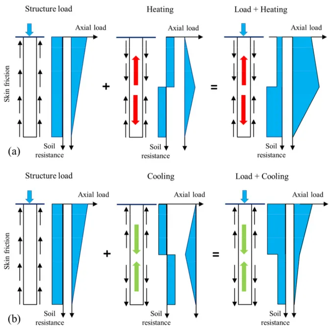
Many studies have been performed in the recent years to investigate on the thermo-mechanical behavior of energy piles. The results evidenced the effects of temperature change on the pile-soil interaction and the mobilized resistance of piles.
Besides, the energetic efficiency of energy pile also depends on the heat exchange condition between pile and surrounding soil. Heat exchange rate of energy pile is strongly affected by the saturation conditions of the surrounding soil. Heat transfer models between pile and surrounding soil have been developed and these models focus on the most relevant process: heat conduction.
Although the large amount of research work done has helped shed light on the problem, more questions have been raised. In the present work, the thermo-mechanical behavior of energy pile in the long-term performance is investigated. In addition, identification of heat transfer problems in heterogeneous media is also considered in this work. Studying the effect of saturated conditions of soil on the thermal parameters will help to better assess the heat transfer between pile and surrounding soil.
The thesis is organized in two parts. The first part focuses on heat transfer in the context of energy pile and includes four chapters.
The Chapter 1 focuses on the literature review. The functioning of thermo-active geostructure is first presented. Secondly, heat conduction models used for heat exchanger borehole and energy pile are analyzed.
GENERAL INTRODUCTION
2
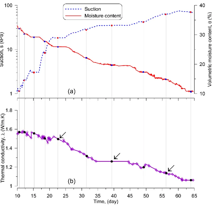
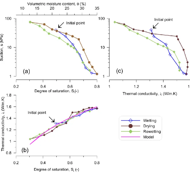
The Chapter 2 presents an experimental study on thermal conductivity of unsaturated soil. Suction, volumetric moisture content and thermal conductivity of a loess sample were measured simultaneously during the application of wetting/drying cycles to the sample. The results show a one-to-one approximately linear relationship between thermal conductivity and volumetric moisture content during the wetting/drying paths.
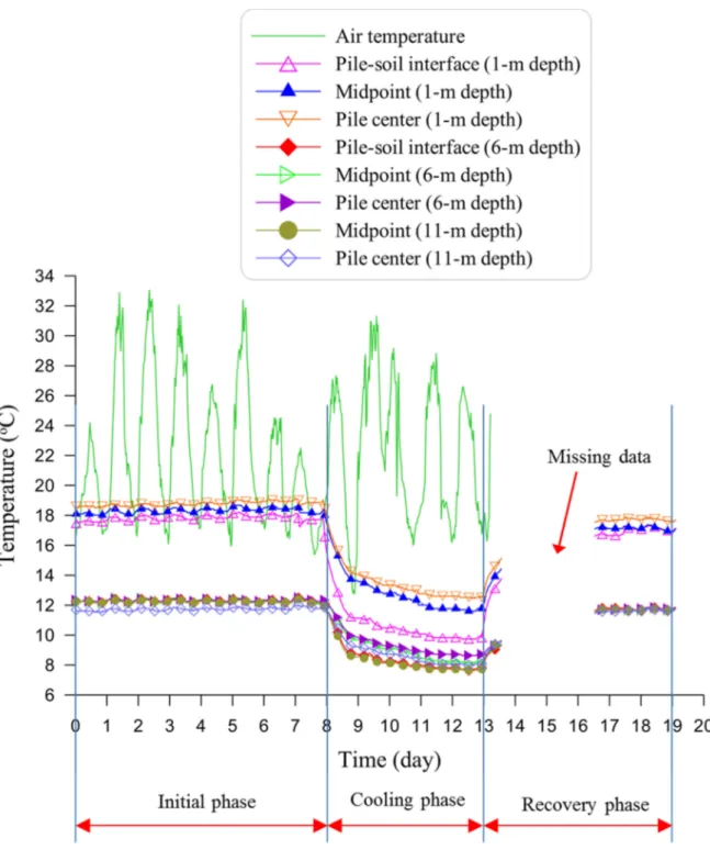
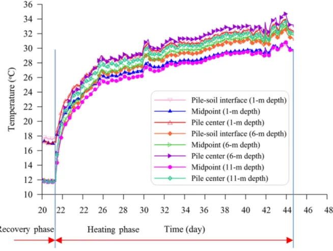
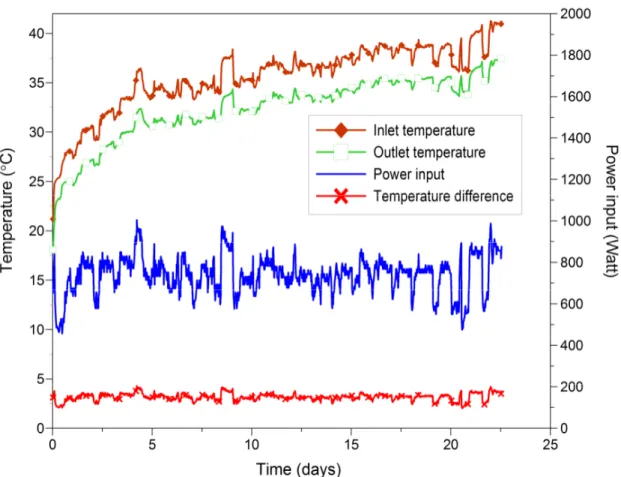
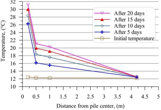
The Chapter 3 presents a full-scale experiment performed with an experimental energy pile. The pile was subjected to heating, cooling and recovery phases respectively. The results show that, with a heat flow rate of 60 W/m, temperature of pile increased from 12°C to 35 °C after 23 days of heating and decreased to 7 °C after one week of cooling.
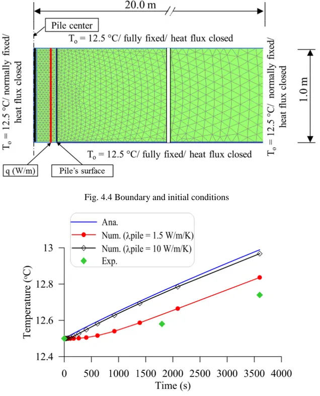
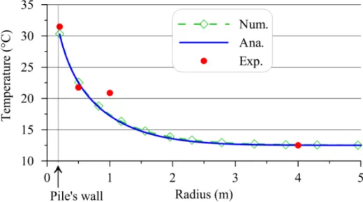
In the Chapter 4, an analytical solution of the heat transfer in surrounding soil is proposed based on the approach of Laplace transform method and also the contour integral method. The analytical solution is then validated by numerical model and the field test data. This solution allows the determination of heat transfer of energy pile in the very short time scales (minutes or less).
The second part of the thesis focuses on the thermo-mechanical behavior of energy pile and includes three chapters (chapters 5 – 7).
A review on the thermo-mechanical behavior of energy pile is shown in the Chapter 5. Existing studies on energy piles are first analyzed following the approaches used: experimental or numerical. Afterward, the behavior of soil and soil-pile interface under thermo-mechanical loading is presented. Finally, the long-term behavior of energy pile is shown.
The Chapter 6 presents an investigation into the long-term behavior of energy pile by using physical modeling. A small-scale model was used to study the thermo-mechanical behavior of energy pile. Experiments have been done in dry sand and then in saturated clay. Thirty heating/cooling cycles (representing thirty years of seasonal temperature changes of energy piles) were applied to the model pile under various constant pile head loads ranging from 0 to 60 % of pile resistance. The results show that thermal cycles under constant head load induce irreversible settlement of the pile head and that the irreversible settlement of the pile head is higher at a higher pile head load.
3
The Chapter 7 presents the numerical modeling of thermo-mechanical behavior of energy pile in clay. The finite element method (Plaxis 2D) was used with coupled thermo-hydro-mechanical analysis. The experiments performed with small-scale pile in clay were first simulated, allowing to better interpreting the experiments and validating the numerical method. Secondly, a full-scale thermo-mechanical experiment was simulated. The results will be used as a scoping calculation for future experiments that will be performed on the full-scale experimental energy piles.
4
PART I. HEAT TRANSFER IN THE CONTEXT
OF ENERGY PILE
5
CHAPTER 1: LITERATURE REVIEW
1.1 Introduction
A thermo-active geostructure is a system that consists of conventional geostructures (e.g. pile foundation, tunnel lining, diaphragm wall, etc.) and individual or several pipe circuits (high-density polyethylene pipes, HDPE) in order to enable heat exchange with the surrounding ground (Fig. 1.1). This system is a part of the Ground Source Heat Pump (GSHP) System that is usually used for heating and/or cooling purpose for buildings (Fig. 1.2). Generally, the GSHP system includes a heat pump and two circuits, and operates like a reverse refrigerator. A heat pump is a machine or device that transfers heat from one location to another using mechanical work. The two circuits, the first one embedded in the geostructures and the second one embedded in structures on the surface, are connected via a heat pump.
CHAPTER 1 LITERATURE REVIEW
6
Fig. 1.2 Scheme of a Ground Source Heat Pump with energy piles and method of energy delivery (after Brandl, 2006)
Thermo-active geostructures have been used since the 1980s in Europe as pile foundations and then as diaphragm walls in Austria. This technology provides a clean energy source contributing to reduce the conventional energy sources consumption and reduce CO2
emissions. Currently, this system has been widely applied in developed countries (e.g. USA, Austria, Switzerland, England, Australia, etc.) in the forms of energy pile foundations, energy tunnels, heat exchanger anchors for thermo-active tunnels, energy walls, etc. Table 1.1 shows that numerous thermo-active geostructures have been built since 2000. Most of them are located in Europe and other developed countries, which are characterized by a temperate climate. Among these structures, energy pile is the most used. Besides, energy tunnels, heat exchanger anchors and other geostructures tend to be used more widely in the exploitation of ground source heat, as some leading energy projects in Austria, the UK, Switzerland and Germany (Franzius & Pralle, 2011; Mimouni et al., 2013; Nicholson et al., 2013; Payne et al., 2010). As shown in Table 1.1, energy obtained from thermo-active geostructures contributes significantly to the total energy for air conditioning of buildings. The GSHP system associated to thermo-active geostructures can thus be used to supply energy independently for buildings, and/or combined with other conventional energy sources.
7
Table 1.1 Examples of thermo-active geostructures applications
Project Country Year Energy (MWh/year) Type of
structure
Climate References
Dock Midfield Zurich Terminal Airport
Switzerland 2003 1170 ( cooling) 306 energy piles Temperate (Adam & Markiewicz, 2009; Pahud & Hubbuch, 2007)
Condominium Great morning, Einsiedeln
Switzerland 2011 262 (heating) 270 energy piles Temperate Data from www.enercret.com
Lainzer Tunnel Austria 2004 - Heat exchanger anchors, Tunnel lining
Temperate (Adam & Markiewicz, 2009; Pahud & Hubbuch, 2007;)
Uniqa Tower, Vienna Austria 2003 468 (heating) 530 (cooling) 7800 m2 diaphragm wall
Temperate Data from www.enercret.com
Vienna Metro line Austria - - Energy lining elements, floor slabs
Temperate (Franzius & Pralle, 2011)
Hotel Sofitel, Viena Austria 2010 960 (heating)
600 (cooling)
100 energy piles and 253 m diaphragm wall
Temperate Datafrom www.enercret.com
STRABAG Headquarters, Vienna Austria 2003 840 (heating) 1450 (cooling) 245 energy piles and 6000 m2 of floor plate layout
Temperate Data from www.enercret.com
Omega-Computers and Peripherals, Vienna Austria 2012 104 (heating) 84 (cooling) 3100 m2 of floor plate layout
Temperate Adapted from www.enercret.com
Dalham Hall Stud, Newmarket
Great Britain
2008 288 (heating)
80 (cooling)
147 energy piles Temperate Data from www.enercret.com
The Keble College, Oxford
Great Britain
2002 133 (heating) 83 energy piles Temperate Data from www.enercret.com
Hospital Valle Belbo,
NizzaMonferrato
Italia 2010 341 (heating)
318 (cooling)
450 energy piles Temperate Data from www.enercret.com
European Central Bank, Frankfurt
Germany 2009 290 (heating)
176 (cooling)
72 energy piles Temperate Data from www.enercret.com
Office Building Timber Port, Hamburg
Germany 2011 1170 (heating)
967 (cooling)
770 energy piles Temperate Data from www.enercret.com
Financial Building, Wuxi
China 2011 4140 (heating)
5600 (cooling)
513 energy piles Tropical monsoon
Data from www.enercret.com
People’s hospital, Yangzhou
China 2014 8260 (heating)
6740 (cooling)
434 energy piles Tropical monsoon
Data from www.enercret.com
Samsung Electronics, Seoul
Korea 1997 - 11150 m2 of
floor plate layout
CHAPTER 1 LITERATURE REVIEW
8
Whereas, in tropical climate countries and specially in the emerging economies - BRICS (Brazil, Russia, India, China and South Africa), energy geostructures use is still limited and does not exploit its huge potential (Zhang et al., 2011). According to the International Energy Agency (IEA) in 2005, the world’s top five CO2 emitting countries (USA, China, Russia,
Japan and India) accounted for 55% of global energy-related CO2 emissions (Resch et al.,
2008). Note that three out of the top five carbon dioxide emitters are emerging economies (Sadorsky, 2009; Bodas Freitas et al., 2012). Among several environmental pollutants, carbon dioxide represents about 58.8% of the greenhouse gases that cause climate change (The World Bank, 2007; Pao & Tsai, 2010). Although China and India are ranked in the top five countries to develop renewable energy, so far, the development of thermo-active geostructures in these countries is still limited.
Actually, in temperate and cold climates the thermo-active geostructures can be used for both cooling and heating demands. The seasonal ground temperature remains relatively constant below a depth of 10÷15 m and values between 10°C and 15°C to a depth of about 50 m (Brandl, 2006; Yasukawa et al., 2009). In tropical and also hot dry climate zones, the thermo-active geostructures systems may play a leading role to provide cooling dominated energy for the building. But this ground heat exchanger system is not easy to achieve in some regions. Actually, the ground temperature may increase due to the GSHP system operation, which in turn affects the long-term performance of the GSHP system. However, literature review in the recent years show that there is still a possibility to use GSHP systems in tropical and hot dry climate regions (Yasukawa et al., 2009; Uchida et al., 2011; De Moel et al., 2010; Bourne-Webb et al., 2009; He & Lam, 2006; Nicholson et al., 2013). The main reasons are the following: (i) the thermo-active geostructures have better heat transfer characteristics than conventional borehole systems; (ii) there is no need for additional land; and (iii) there is no need for drilling of holes to install heat exchangers.
Moreover, this system can be combined with outdoor systems such as solar panel on the roof (plate heat exchanger) or nocturnal cooling radiator, cooling tower or domestic hot water production device to reduce the heat rejected into the ground, namely a hybrid GSHP system (Man et al., 2009; Man et al., 2011; Sagia et al., 2012). This makes sense if wasted heat can be used to keep ground thermal balance in the cooling load operation period and to increase the coefficient of performance of the GSHP system.
In this chapter, heat transfer aspects related to thermo-active geostructure are first reviewed (section 1.2). Secondly, an overview on the heat conduction analysis related to energy pile is
9
presented (section 2.2.). That provides a general background for the works done in the Part I of this thesis that focuses on the heat transfer in the context of energy pile.
1.2 Thermo-active geostructure
1.2.1 GSHP system operation
GSHP system is one of the fastest growing applications of renewable energy in the world, with annual increases of 10 % in about 30 countries in the last decades (Curtis et al., 2005). Some of the main advantages of GSHP system can be listed as follows (Curtis et al., 2005; Omer, 2008; Permchart & Tanatvanit, 2009; Ozgener & Hepbasli, 2007; Brandl, 2006):
• Saves fossil fuel energy and reduce CO2 emissions,
• Highly reliable (few moving parts, no exposure to weather),
• Not noisy and no unsightly outdoor unit is needed,
• More efficient than air source heat pumps,
• Uses electricity only to transfer heat, and does not generate it by the burning fuel or using electric resistance elements.
To evaluate the performance of the GSHP system in the heating mode, the Coefficient of Performance (COP) is used. COP is the heating capacity of the unit divided by its electrical input (Brandl, 2006):
[ ]
[ ]
Energy output after heat pump kW COP
Energy input for operation kW =
(1.1)
The ISO 13256-1 standard recommends that COP must be higher than 3.3, and should be greater than or equal to 4 for economic reasons (Mimouni et al., 2013). To ensure this condition for heating mode, ground temperature should not be lower than 0÷5°C and the output temperature in the secondary circuit should not exceed 35÷45°C.
In the cooling mode, to evaluate the performance of the GSHP system, the Energy Efficiency Ratio (EER) is used. EER is defined as cooling capacity of the unit divided by its electrical input (AHRI, 1998).
[Btu]
[
. ]
Output cooling energy
EER
Input electrical energy W h
=
CHAPTER 1 LITERATURE REVIEW
10
As recommended by the American Refrigerant Institute (ARI), EER should be in the range of 10 to 18.6 (Inalli & Esen, 2005), and after the ISO 13256-1 standard EER value must be greater than or equal to 14.1.
In the areas where both heating and cooling are needed, in winter the GSHP system provides heat for buildings and cools down the ground, and vice versa in summer. However, at the beginning of cold season, heating demand is not important while the ground temperature is high. Reversely, at the beginning of hot season, cooling demand is low while the ground temperature is low. The COP and EER values change then constantly depending on the ground temperature and the buildings’ demand. Accordingly, the ratio of the usable energy output of the system to the energy input to the system is known as the seasonal performance factor (SPF) (Brandl, 2006).
[
]
[
]
Usable energy output of energy system kWh
SPF
Energy input of the energy system kWh
=
(1.3)
This important factor is necessary to evaluate the seasonal variations of the COP and EER. SPF is dependent on the heat pump, local climatic conditions, and also on the other energy consuming elements (Brandl, 2006; Mimouni et al., 2013).
1.2.2 Ground temperature and soil thermal properties
The knowledge of the ground temperature plays an important role for the design of thermo-active geostructures. Low-temperature soil can be used to cool down the building in summer, while high-temperature soil is suitable to heat the building in winter. But in the regions with year-round high atmospheric temperature, if the soil temperature is high the application of GSHP system is not suitable (Pouloupatis et al., 2011). The ground temperature distribution is affected by the following factors (Farouki, 1986; Popiel et al., 2001; Florides & Kalogirou, 2005; Omer, 2008; Singh et al., 2011; Pouloupatis et al., 2011; Akrouch et al., 2013):
• Climatic factors (air temperature, wind, solar radiation, air humidity, rainfall, etc.)
• Structure and physical properties of the ground
• Ground surface cover (snow, trees, etc.)
These properties have strong effects on the capacity of the ground to transfer heat and of the geostructure to exchange heat. Besides, the ground temperature-depth relationship can be separated into three different zones around the thermo-active geostructure as follows (Popiel et al., 2001; Wang & Qi, 2008; Nguyen et al., 2017):
11
• Surface zone: (0 ÷ 1 m depth), subsurface mostly absorbs heat from solar radiation throughout the year. In most regions, poorly shaded landscapes may contribute to high temperatures in soils.
• Shallow zone: (1 ÷ 10 m depth), where soil temperature is almost constant and approximately equals to the average air temperature, but still affected by the seasonal temperature fluctuation.
• Deep zone: (> 10 m depth), ground temperature is constant throughout the year. The three main forms of heat transfer process in soils are conduction, convection and radiation. Among them, convection and radiation generally have relatively small or negligible effects, however they may have a noticeable influence in certain situations (e.g. in regions with high groundwater flow) (Rees et al., 2000). Heat conduction due to temperature gradient is the most relevant process associated with heat transfer in soils (Farouki, 1986; GSHP Association, 2012). The most important thermal properties of soil are thermal conductivity and volumetric heat capacity, which are key for the design of thermo-active geostructure systems (GSHP Association, 2012). The thermal conductivity of soils and rocks is in the range of 0.2 W/(m.K) to 5 W/(m.K). This value is controlled by the structure and physical properties of soil and rock with the solid particles being the most conductive, followed by water and then air. As the thermal conductivity is highly dependent on soil’s density and water content, wet or saturated soils have higher (about five times) thermal conductivity than dry soil (Riederer et al., 2007). In addition, volumetric heat capacity of soil also depends on the water and air contents. When soil temperature changes over time, assessment of the ability to diffuse heat as well as to store thermal energy in the ground is done by using the thermal diffusivity, which is defined as the ratio of the thermal conductivity to the volumetric heat capacity of the ground. Thus, soil thermal properties have an important role in the design of heat exchanger geostructures (Brandl, 2006; De Moel et al., 2010; Omer, 2008; GSHP Association, 2012; Suryatriyastuti et al., 2012; Mattsson et al., 2008):
• The thermal conductivity of soil acts as a standard value to design the number of heat exchanger piles as required to provide energy for building;
• Dry or unsaturated soil with smaller thermal conductivity may require deeper energy piles foundation and larger area of the heat exchanger;
• Depending on soil properties and depth of boreholes, 1 kW heating in saturated soil needs from 20÷35m2 (and in dry soil from 35÷50m2) of surface of concrete structures in contact with soil or groundwater.
CHAPTER 1 LITERATURE REVIEW
12
In addition, in areas with existence of groundwater flow, the effect of thermal conduction and also advection in the soil contributes to accelerate the process of heat extracted from/rejected to the soil around heat exchangers and it affects the sustainable operation of GSHP system.
Studies on heat exchange between energy piles and the ground in unsaturated state showed that the heat exchange rate of energy pile is strongly affected by the saturation conditions of the surrounding soil (Yun & Santamarina, 2008; Thomas & Rees, 2009; Choi et al., 2011; Dong et al., 2015; Akrouch et al., 2015). Choi et al., (2011) indicated that the heat exchange rate of energy pile in unsaturated soil (water table at the pile’s toe) is 40% smaller than that in fully saturated soil (water table at the ground surface). Thomas & Rees (2009) showed that that heat exchange rate of a raft foundation located 10 m above the water table was 35% smaller than the case where it was located below the water table.
1.3 Heat conduction analysis
In the range of vertical heat exchanger borehole and energy pile, heat is diffused from the pipes into the concrete and then to the surrounding soil. As mentioned above, heat conduction is the most relevant process associated with heat transfer in soil and pile. Therefore, various analytical and numerical solutions have been proposed to simulate the conductive heat transfer of heat exchanger pile.
Analytical models (Jaeger, 1944; Carslaw, 1947; Zeng et al., 2002; Lamarche & Beauchamp, 2007; Bandos et al., 2009; Man et al., 2010; Bozis et al., 2011; Li & Lai, 2012a and 2012b; Akrouch et al., 2015), for simplicity, have been developed with the following general assumptions: heat transfer is purely conductive; the surrounding medium is homogeneous and infinite or semi-infinite; the initial temperature is homogenous; the influence of ground surface temperature is ignored; a constant heat flow is applied at the pipe boundaries and the vertical heat transfer can be neglected. Most of the analytical heat transfer models have been developed mainly for borehole ground heat exchanger system (GHE).
The existing analytical models of heat transfer can be divided into two groups: the first one is applicable for homogeneous media and the second one for composite media. Most of these models are only valid after a certain time of operation and they are generally suitable for long-term heat exchanger performance. It means that temperature of borehole reaches a steady state as soon as the heat exchanger system is activated. This is acceptable when the diameter of heat exchanger borehole is much smaller than its length, as well as the instantaneous heat
13
transfer is not much of interest. However, energy pile has larger diameter and smaller length than those of a borehole. As a result, heat transfer inside the pile takes a longer time to reach the steady state, and pile often has different thermal properties from the surrounding soil.
Based on the theory of infinite line source model, Carslaw & Jaeger (1959) developed a 1-D solution of heat transfer in homogeneous media (equation 1.4), under constant heat flow condition. This model is relatively simple and it can be used to estimate the soil temperature around a heat exchanger borehole quickly.
2 2 4
4
4
4
u r i tq
e
q
r
T
du
E
u
t
απλ
πλ
α
− ∞
∆ =
= −
−
∫
(1.4) with:( )
u i xe
E
x
du
u
∞ −=
∫
For a small value of x:
( )
1
2 3ln( )
(
)
4
i
E
−
x
= +
γ
x
− +
x
x
+
O x
(1.5)This exponential integral Ei is expressed as a logarithmic function that was validated by
Abramowitz & Stegun (1972). In this solution, ∆T is the change of temperature,
λ
is the soil thermal conductivity (W/mK),α
is the soil thermal diffusivity (m2/s), r is the distance from heat source, q is the heat flow rate (W/m),γ
= 0.5772 is Euler’s constant, t is the elapsed time of heating operation and O(x3) is the infinitesimal function.Eskilson (1987) developed a 2-D analytical solution for a finite line source model. This model is applied for the case a borehole having a limit length, in which temperature of the surrounding soil depends on those of the line source and on the surface. This latter considers only the heat transfer from the borehole’s wall to the surrounding soil. Temperature at the borehole’s wall is assumed to be constant over the depth and depends only on time. The solution of Carslaw & Jaeger (1959) on temperature of borehole Tb can be expressed in
another way as follows:
.
(t)
b b
T
=
q R
(1.6)The thermal resistance of soil Rb(t) can be taken approximately as follows:
2
4
1
(t)
ln
4
b bt
R
r
α
γ
πλ
=
−
(1.7)CHAPTER 1 LITERATURE REVIEW
14
To apply the model to the borehole/pile with a diameter rb and a finite length H, the author
suggested that t must satisfy the inequality:
< < .
Where the lower limit is necessary for the use of a line source at r = 0. In case of conventional borehole/pile, this lower limitcorresponds to a few hours. And
=
2
9 is the time in which the heat exchange reaches its steady state that varies between several days to years. In a larger time, 3D problems should be considered. The results show that, when the heat exchange does not reach the steady state,
temperature response function depends only on the dimensionless variables
and
.
Thethermal resistance is then expressed in G-function as follows:
1
,
(t)
2
b b sr
t
R
G
t
H
πλ
=
(1.8)Here, G-function is also called temperature response function of the borehole’s wall.
In general: 2
5
1
ln
ln
;
(1.9)
2
2
,
ln
;
(1.10)
2
b s b s b s s bH
t
r
t
t
r
t
r
t
G
t
H
H
t
t
r
α
+
< <
=
>
The G-function, shown in equation (1.9), is used to determine the wall’s temperature of a single borehole. For example, by using this G-function measured with a conventional borehole (0.11 m in diameter, and 110 m long;
λ
= 3.5
W/(m.K) and = 1.62. 10 m2/s) Eskilson (1987) found that the steady state is reached after 26 years. That is why this solution (equation 1.9) is often used in practice. However, in the case of energy pile, with a larger diameter and much smaller length than heat exchanger borehole, the steady state is obtained after several days to one year (Bozis et al., 2011). It can be seen that, these G-functions are only suitable with long-term heat transfer problems and with a borehole having a small diameter.Practically, the heat exchange rate of the ground heat exchanger system changes hourly and depends on the energy requirements of the building. This change directly affects the COP of the system. Study of Yavuzturk & Spitler (1999) shows that the temperature fluctuation in
15
short term typically varies up to 5.6 ÷ 10°C over a given day. Therefore, prediction of short-term temperature exchange allows deshort-termining exactly the building’s energy consumption.
Yavuzturk & Spitler (1999) have extended the application of Eskilson’s G-functions to simulate the short-time response of heat conduction exchanger borehole by using a 2-D numerical model. This is the first solution, related to the problem of transient heat of heat exchanger borehole, which considers different thermal properties between the borehole and surrounding soil. Later, Zeng et al. (2002) proposed a 2-D model of a finite line heat source that represents the effect of heat transfers along the axis of the vertical borehole and the temperature at the ground surface. This model is used to determine the temperature outside the finite length of heat exchanger borehole, in short-time operation (equation 1.11a).
(
)
(
)
(
)
(
)
(
)
2 2 2 2 0 2 2 2 2 ' ' ' , , 2 2 4 ' ' H erfc r z z erfc r z z q T r z t t t dz r z z r z zα
πλ
+ − + − ∆ = − + − + + ∫
(1.11a)with erfc is the complementary error function, commonly denoted erfc(z), is an entire function defined by:
( )
2
t2 zerfc
z
e dt
π
∞ −=
∫
(1.11b)At longer time, the transient solution becomes:
(
)
( ) ( ) 2 2 2 2 2 2 2 2 2 2 2 ln . , , 4 H z z z z q H z T r z t H z H zϕ
ϕ
ϕ
πλ
ϕ
ϕ
− + + − + + + ∆ = − + + + (1.12)where, H is the depth of the borehole, z is the depth, and is the radial coordinate.
Base on the 1-D solution of Carslaw & Jaeger (1959), Bozis et al. (2011) analyzed heat transfer of an energy pile with 2n heat pipes and a constant injection heat flow per pipe. The authors have proven that the temperature at the pile center is dependent neither on the number of pipes nor on the pipes’ diameter. Actually, it depends on the total injection heat flow at a given time, the distance with the pipes and also the pile thermal properties.
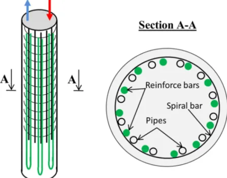
In contrast to the line source model with the heat source located in the center of borehole/pile, when the heat sources are close to the pile edge and distributed as a hollow cylinder shape, the temperature response model behaves as a cylinder model (Fig. 1.3).
CHAPTER 1 LITERATURE REVIEW
16
Fig. 1.3 The arrangement of pipes close to the pile edge
Therefore, a heat transfer model with cylindrical geometry is necessary to simulate more accurately the heat transfer in this case. Based on the complex variable theory and the Laplace transform method, Carslaw & Jaeger (1947)also developed an exactsolution for the problem of the infinite hollow cylinder heat source (equation 1.13).
(
2)
0( )
1( )
( )
0 1( )
( )
0 0( )
2 2 2 2 0 0 1 0 1 01
u tJ
Y ur
J ur Y
q
ur
ur
du
T
e
r
J
ur
Y
ur
u
αλ π
∞ −−
∆ =
−
+
∫
ɺ
(1.13)Here, Ji and Yi are Bessel functions of the first and second kinds of order i.
Recently, Man et al. (2010) have developed new cylinder surface source models by assuming that the material inside and outside the surface is homogeneous. By using the Green’s function method, they found the expression of soil temperature in 1-D model as follows:
( )
(
2 02)
(
0)
0 01
exp
.
'
,
2
4
'
4
'
'
lrr
q
r
r
T
r
I
d
ττ
τ
πλ τ τ
α
α
τ τ
τ τ
+
∆
=
−
−
−
−
∫
(1.14)The 2-D model that represents the simultaneous influence of a finite cylindrical heat source and the boundary ground surface is showed in equation (1.15).
17
(
)
(
)
(
)
(
)
(
)
(
)
2 2 0 0 0 0 0 2 2 2 01
exp
, z,
2
4
8
'
'
'
'
exp
'
'
4
'
h lrr
q
r
r
T
r
I
c
r
r
z
z
dz d
ττ
ρ
α
α
πα
τ τ
τ τ
τ τ
τ
α τ τ
+
∆
=
−
−
−
−
−
+ +
+
−
−
∫ ∫
(1.15)where ( ) = ! exp ( cos )) is the modified Bessel function of the first kind of zero order.
For heat transfer models that consider different thermal properties between the pile and the surrounding soil, Lamarche & Beauchamp (2007) presented a closed-form solution of transient heat inside a heat exchanger borehole. An equivalent pipe is placed in the center of borehole and this equivalent pipe is considered as an infinite cylindrical heat source. Heat mass capacity of fluid inside the pipe is ignored and the pipe’s temperature is supposed to be uniform. Equation (1.16) shows the transient heat function of the borehole.
(
2)
( ) ( )
1( ) ( )
1 4 2 0 2 2 44
1
u t o o soilY
J
J
Y
q
ur
u
ur
u
du
T
e
u
αλ
λ π δ
φ ψ
∞ −−
∆ =
−
+
∫
ɶ
ɺ
ɶ
ɶ
(1.16) where( ) (
) ( )
(
) ( )
( ) (
) ( )
(
) ( )
( )
(
) ( )
(
) ( )
( )
(
) ( )
(
) ( )
1 0 1 1 0 1 0 1 1 0 1 0 1 1 0 1 0 1 1 0 Y Y J Y J J Y Y Y Y J J Y J Y Y J J J J φ β βδγ βδ βδγ βδ λγ β βδγ βδ βδγ βδ λγ ψ β βδγ βδ βδγ βδ λγ β βδγ βδ βδγ βδ λγ = − − − = − − − ɶ ɶ ɶ ɶ/
;
/ ;
/
soil piler
r r
er
pr
eλ λ
ɶ
=
λ
ɶ
=
δ
=
where r is the distance from the heat source, re the pipe radius, and rp the pile radius. The
advantage of this model is that it allows analyzing heat transfer inside borehole in a very short time.
Li & Lai (2012a) has also developed a solution for a continuous line source model in composite media (equations 1.17 & 1.18). This solution is developed from the solution of an instantaneous line source in composite media of Jaeger (1944). This new model uses the superposition method to solve the problem with multiline sources inside the pile. The temperature response function is then expressed as a G-function; this concept was first proposed by Eskilson (1987).
CHAPTER 1 LITERATURE REVIEW 18
(
)
( )(
)
( ) ( )(
)
(
)
2 1 0 0 2 2 1 0 1 , , cos 1 exp 2 n n n J vR J vR g f G F R n v F dv vϕ ψ
θ
πλ
θ θ
ϕ ψ
+∞ +∞ =−∞ − ′ =∑
− ′∫
− − + (1.17)(
)
( )(
2)
( )[
(
( ))
( )]
2 0 2 0 2 2 2 2 0 1 , , cos 1 exp n n n n J vR J vR Y vR G F R n v F dv v ψ α ϕ α θ π λ θ θ ϕ ψ +∞ +∞ =−∞ − ′ = − ′ − − +∑
∫
(1.18)
where F0 is the Fourier number, R and
θ
are the coordinates of the line source in thecylindrical coordinates, and
λ
andλ
* are thermal conductivities of pile and soil, respectively.( ) ( )
( ) ( )
( ) ( )
( ) ( )
( ) ( )
( ) ( )
( ) ( )
( ) ( )
n n n n n n n n n n n n n n n nJ
v
J
v
J
v
J
v
J
v
Y
v
J
v
Y
v
f
Y
v
J
v
Y
v
J
v
g
Y
v
Y
v
Y
v
Y
v
ϕ αλ
α
α
ψ αλ
α
α
αλ
α
α
αλ
α
α
′
′
=
−
′
′
=
−
′
=
−
′
′
=
−
(1.19)where +, and -, are Bessel functions of the first and second kinds of order n; = . / * , where and * are thermal diffusivities of pile and soil, respectively;
λ
=λ
*/λ
.In case of pile with a U-pipe source, the G-function inside the borehole is:
(
)
(
2)
2( )
2( )
2(
(
)
(
)
)
0 1 0 2 2 1 0 1 , , 1 exp 2 2 m A m B m p m J vR J vR J vR g f F R R G v F dv vϕ
ψ
πλ
ϕ ψ
+∞ +∞ =−∞ + ′ − ′ = − − +∑ ∫
(1.20) In case of double U-tubes:(
)
(
2)
4( )
4( )
4(
(
)
(
)
)
0 1 0 2 2 1 0 1 , , 1 exp 2 2 l A l B l p l J vR J vR J vR g f F R R G v F dv vϕ
ψ
πλ
ϕ ψ
+∞ +∞ =−∞ + ′ − ′ = − − +∑ ∫
(1.21) where, RA and RB are dimensionless radial coordinates, values of n in definitions equation(1.19) equal 2m and 4l;
It can be seen that this model refers to the presence of thermal properties of two materials. However, the solution is relatively complex and each type of U-tubes configuration requires a different G-function. This solution is only applicable for the short-term performance of the ground heat exchanger system.
Besides, Li & Lai (2012b) have developed cylindrical-surface and spiral-line sources solutions for the thermal pile with finite length (equation 1.22). The model considers anisotropic medium around the heat source. The comparison between the cylindrical-surface and spiral-line sources shows that the temperature of both models has similar values at the pile wall. The effect of anisotropic medium around the pile is found negligible in the short-term period of pile heating or cooling.
19 2 0
'
1
1
2
'
2
4
n l z z x yd
d
q b
T
erfc
erfc
d
t
t
d
d
πβ
α
α
π λ λ
∆ =
−
∫
(1.22) with
(
)
(
) (
)
(
)
(
) (
)
2 2 2 2cos
'cos
sin
'sin
'
cos
'cos
sin
'sin
zx zy zx zy
d
r
r
r
r
z b
d
r
r
r
r
z b
κ
ϕ
β
κ
ϕ
β
β
κ
ϕ
β
κ
ϕ
β
β
=
−
+
−
+
−
=
−
+
−
+
+
In the majority of the existing models, the solutions are usually represented in symbolic functions form and therefore solving them must be done by numerical integration methods, by using programs like Matlab, Maple, Maxima, etc. These models are called semi-analytical solutions. Practically, the results obtained from the analytical solution have an excellent accuracy but the existing heat transfer solutions, used for transient heat in heterogeneous medium, are usually represented in complex forms. For these reasons, empirical models are also considered. Actually, empirical models are often expressed as simple mathematical forms and give approximate results when compared with analytical models.
Loveridge & Powrie (2013b) have developed empirical solutions that were based on the 2-D finite element analyses of Loveridge & Powrie (2012a) and the analytical solution of Man et al. (2010). The ground temperature response functions (G-functions) were obtained by fitting the numerical simulations. Advantages of these new G-functions are that they consider typical geometries of heat exchanger piles (e.g. pile sizing, pipes arrangement and the relative thermal properties of pile and soil). In addition, they allow estimating heat storage inside the pile and soil in both short- and long-term operations. For the short-term behavior of ground temperature response, the G-function is based on 2D simulation and it can only be validated within the timescale of F0 = 0.1 ÷ 10. In which F0 = /01* is the Fourier number. Equation
(1.23) is the proposed ground temperature response function that is based on the simplified line source model. Equation (1.24) is based on simplified solid cylinder model.
( )
01
ln 4
2
G
=
F
−
γ
(1.23) and ln 45*6 = −2.321016 + 0.499615 ln(:;) − 0.027243=ln(:;)>*− 0.00525=ln(:;)>?+ 0.000264311=ln(:;)>@ + 0.00006873912=ln (:;)> (1.24)
CHAPTER 1 LITERATURE REVIEW
20
It can be said that this model is simpler than the analytical model of Li & Lai (2012a). For the long-term behavior, the ground temperature response is based on the 3D simulation. That means the model mentioned the influence of temperature on the ground surface when the pile has short length. The G-function for this case is showed in the Fig. 1.4, where the empirical G-function is fitted with eight curves that are represented for four aspect ratios (AR) of 15, 25, 33 and 50; and each aspect ratio has been simulated with only the upper and lower bound scenarios. After Loveridge & Powrie (2013b) the upper bound solution corresponds to piles with pipes situated near the pile edge of cross section and thermal conductivity of pile is larger than that of soil. The lower bound solution corresponds to piles with pipes situated in the center and thermal conductivity of pile is smaller than that of soil. The authors have also indicated that, in case of the lower bound the response tends to get closer to the line source model, and inversely the response of the upper bound will moves closer to the solid cylindrical model.
Equation (1.25) shows the G-functions for the upper bound solution with F0 > 0.1, and lower
bound solution with F0 > 0.25.
B = C=ln(: )>D+ E=ln(: )> + F=ln(: )> + )=ln(: )>@+ G=ln(: )>? + H=ln(: )>*+
I=ln(: )>ℎ (1.25)
The result in the Fig 1.4 is a combination of 2-D and 3-D model, in which the ground temperature response is shown in both short- and long-terms. It can be seen that, with F0 < 10
there is only two distinguished curves that related to the lower and upper bound, the response is only governed by the pile’s parameters (size, number of pipes and its arrangement) but not by the aspect ratio. However, in the long term, F0 > 10, the response depends on the aspect
ratio but the two bounds are close to each other. Especially, the ground temperature responses in four aspect ratios are equivalent and they are well fitted with the finite line source model.
21
Fig. 1.4 Ground heat exchanger G-function for long-term operation, (after Loveridge & Powrie, 2013b)
Besides, finite element method (FEM) have been also used to analyze heat transfer problem of borehole and pile in composite media (Bauer et al., 2011; Ghasemi-Fare & Basu, 2013; Ozudogru et al., 2015). In general, this method is capable of simulating complex problems of heat exchanger piles in which the temperature response function is affected by a large number of parameters such as different thermal properties, pile sizes, number and distribution of heat pipes, timescale, etc. Meanwhile this is not possible with the analytical method. Although FEM is a powerful tool to solve different problems, it can be used to study the impact of various parameters on heat transfer. However, the finite element method is predominately used for research instead of being used as a design tool. Therefore, a simple analytical solution is always useful.
1.4 Conclusions
Thermo-active geostructure has been applied in various developed countries since the 1980s for heating and also cooling building. In general, the operation principles of thermo-active geostructure are similar to that of the GSHP system. In addition, the thermo-active geostructure can be used to supply energy independently or combined with other conventional energy sources for the buildings. However, unbalance heating and/or cooling loads in the long
CHAPTER 1 LITERATURE REVIEW
22
term causes heat or cold accumulation in the ground, thus the COP of the system gradually reduces.
Practically, the heat exchange rate of energy pile is influenced by thermal conductivity of the surrounding soils. Soil density and water content are generally known as the major factors that influence the thermal conductivity. Therefore, thermal conductivity of soils is considered as an important parameter for the design of energy pile.
Among the existing analytical heat conduction models, the conventional models of heat conduction in pile and surrounding soil are applicable after a certain period of time when the process reaches its steady state. Recently, some models have been proposed to address the problem of transient heat but most of them are quite complex for the use as a simple design tool. Therefore, a simpler analytical heat transfer solution would be useful for the optimization of the energy pile design process.