HAL Id: hal-01760345
https://hal.archives-ouvertes.fr/hal-01760345
Submitted on 20 Jun 2018
HAL is a multi-disciplinary open access
archive for the deposit and dissemination of
sci-entific research documents, whether they are
pub-lished or not. The documents may come from
teaching and research institutions in France or
abroad, or from public or private research centers.
L’archive ouverte pluridisciplinaire HAL, est
destinée au dépôt et à la diffusion de documents
scientifiques de niveau recherche, publiés ou non,
émanant des établissements d’enseignement et de
recherche français ou étrangers, des laboratoires
publics ou privés.
Antenna Ysing Vacator Diode for Wireless
Communication
Ines Rouissi, Jean Marie Floc’h, Trabelsi H.
To cite this version:
Ines Rouissi, Jean Marie Floc’h, Trabelsi H.. Design of Frequency Reconfigurable Multiband
Mean-der Antenna Ysing Vacator Diode for Wireless Communication. International journal of advanced
computer science and applications (IJACSA), The Science and Information Organization, 2017, 8 (3),
�10.14569/IJACSA.2017.080324�. �hal-01760345�
Design of Frequency Reconfigurable Multiband
Meander Antenna Using Varactor Diode for Wireless
Communication
I.ROUISSI
URCRFS, FSTUniversity of Tunis El Manar, 1002 Tunis, Tunisia
J.M.FLOC’H
IETR, INSA Rennes 20 avenue Buttes de coësmes, 35043Rennes, France
H.TRABELSI
URCRFS, FSTUniversity of Tunis El Manar, 1002 Tunis, Tunisia
Abstract—A compact multiband frequency reconfigurable
meander antenna proposed for wireless communication systems is designed and described in this paper. A folded structure has been chosen due its good tradeoff between size, bandwidth and efficiency. The reference antenna is based on a meander patch structure radiating at F1=1, F2=1.94, F3=2.6GHz and optimized to be integrated in the Printed Circuit Board (PCB). In order to sweep the resonance frequencies, a chip capacitor was inserted between the meander patch printed on the top layer and a floating ground plane on the back one, in first case. Than in second case, by inserting a varactor diode to tuning electronically the resonance frequencies over wide bands. The measured results agree with simulations and good radiation properties were obtained. Realized prototype and related results are indeed presented and discussed.
Keywords—Frequency reconfigurable meander antenna; chip capacitor; Varactor diode; Size reduction; tuning range; wireless communication
I. INTRODUCTION
Wireless communication have been grown strongly and developed significantly in recent years. These new communication systems use multiple standards, e.g. (Radio, TNT, GSM850, GSM1800, GSM1900, WiFi, WLAN, LTE,…), operating on many frequency band for various applications. This evolution opens the field to the development of frequencies reconfigurable antenna. This type of antenna presents a promising alternative to multiband and ultra large band (ULB) because of its ability to adjust its operating frequency band with sometimes-dynamic agility.
Frequency agility can be achieved using several techniques such as PIN diode, varactor diode, MEMS, liquid cristal… Several prototypes have been studied to define frequency reconfigurability. For example, a frequency reconfigurable multiple-input-multiple-output (MIMO) monopole antenna was designed in [1], using a pin diode and a wide frequency tuning ranging from 1.88 to 2.64GHz was achieved. In [2], a compact folded monopole with a transparent dielectric loading was presented. Also, a tuning range from 419 to 883MHz was achieved, by controlling the voltage of varactor diode. A reconfigurable microstrip rectangular loop antenna is discussed in [3]. The physical perimeter of the loop antennas is electronically modified by controlling the states of the MEMS
switches. The resonance frequency shifts from 1.16 to 2.08GHz. Reference [4], demonstrated a monopole antenna achieving a frequency tenability from 1.7 to 3.5GHz, by using a movable metallized plate inside a microfluidic channel.
However, many engineers are interested in the electronic components for easy integration, high reliability and small size. The MEMS present some inconvenient including high activation voltage, higher cost and lower reliability. Compared with an MEMS switch, the varactor diode has better reliability, faster switching speed and lower applied voltage. This is the main reason why many researchers and industrial are interested in the varactor diode instead of MEMS switches for frequency tuning.
Compact communication systems working in these standards required a compact size [5], low cost and multiband antenna [6-8]. Meander technologies are the most investigated for the design of reconfigurable structures [9], which allows small size designs, by increasing the electric length of the patch, and wide band operations [10]. Several meander reconfigurable antenna designs were reported in the literature for wireless applications.
A microstrip monopole reconfigurable antenna is presented in [11]. The antenna size of 25×12mm2, operates at two bands (2.3- 2.4GHz) and (5.15- 5.35GHz). The frequency tuning was produced by inserting a PIN diode and a varactor diode into a meander. The PIN diode is used for switching wireless services and the varactor diode is used for tuning agility. In [12], an electrically small antenna (ESA) based on the meander antenna structure is proposed. This antenna with size of 23.5×43mm² operates in the 800MHz band of LTE. The antenna is of higher size with respect to the other structure.
In [13], a frequency reconfigurable planar monopole antenna for cognitive radio has been designed for wide tuning range. The radiator antenna composed of meandering element and a U-shape was connected together using a PIN diode. Depending on the state of the PIN diode ON or OFF, the antenna resonates eithers at 2.39 and 2.96GHz. More agility from 2.69 to 3GHz was achieved by placing a varactor diode on the radiator antenna. The designs proposed in [11-13] were meander structure, covering high frequency band above 2GHz and, hence are not suitable candidates for low-frequency mobile standards and wireless handheld devices.
In this paper, a frequency reconfigurable meander antenna is presented for wireless communications systems. The structure is based on a meandering line. The frequency agility was achieved by embedding firstly, a chip capacitor then a varactor diode. The advantage given in this structure resides in its small size 12×15mm² with multiband behavior (4 bands). Compared to the existing designs, large tuning range is obtained from 0.7 to 2.87GHz when inserting a single varactor diode. The planar structure and its operation at low-frequency band below 1GHz are the key features of the proposed design. The distinguishing feature of the proposed antenna is that can be easily integrated into a Printed Circuit Board PCB useful for mobile phone.
II. ANTENNA GEOMETRY
The geometry of the proposed reconfigurable antenna is displayed in Fig.1. It is printed on 150×70mm² commercially available FR4 dielectric substrate with a permittivity of 4.4 and a thickness of 1.6mm. The meander patch was printed on the top layer coupled with a floating ground plane placed on the back layer.
Fig. 1. The meander antenna
Adding a floating ground plane under the meander patch allows changing the effective permittivity of the antenna. Thus, an increase of the electrical length of the meandered line antenna structure and hence results in reducing the overall size of the antenna. In fact, the meander behaves as an inductive structure. The variation in the spacing between the meander lines varies the coupling between them, and therefore the generation of the resonance frequencies. Hence, the multiband behavior.
Fig. 2. Simulated and measured return loss S11 of the meander antenna
The simulated and measured return loss of the optimized antenna are shown in Fig.2. The planar compact antenna operates in simulation at F1=1GHz, F2=1.94GHz, F3=2.6GHz and in measured results F1=1.04GHz, F2=2.01GHz, F3=2.71GHz. It is noted that good agreement between simulated and measured results are obtained.
3D pattern of the antenna was displayed for the operating frequencies in the 1.04, 2.01 and 2.71GHz, presented in Fig.3.
Fig. 3. Measured 3D radiation pattern at: (a) F1=1.04, (b) F2=2.01 and (c) F3=2.71GHz
As shown, this pattern is almost circularly symmetric around x-axis and has a null value for φ=0° at all the resonant frequencies. It can be seen in F1=1.04GHz that the proposed structure presents omnidirectional radiation pattern in the yz-plane with a peak gain of -1.32dB, confirming the appearance monopoly antenna. In the 2.01GHz and in the xz-plane, the antenna has a peak gain of 0.36dB. The pattern in φ=0° and 90° has a null value. In 2.71GHz, the proposed antenna presents quasi-omnidirectional radiation pattern in the yz-plane with a maximum gain of 2.18GHz.
III. FREQUECNY AGILITY ANTENNA
We are interested in this part, to investigate the frequency agility of the proposed meander antenna. First, the study was done using a single lumped capacitor to identify the suitable position to tune the resonance frequency. Then by embedding a varactor diode to achieve a large tuning frequency range.
A. Lumed capacitor
Fig. 4. The meander antenna loaded with a chip capacitor
In order to have a frequency agility property, a chip capacitor was loaded between the meander patch on the top side and the floating ground plane on the backside. The proposed structure was depicted in Fig.4. When the capacitance values varied from 1.3 to 5.2pF, we obtained a tuning range of 100MHz[0.94GHZ-0.84GHz]for the first frequency F1, 40MHz [1.9GHz-1.86GHz] for F2, 260MHz [2.46GHz-2.2GHz] for F3 and 200MHz [2.98GHz-2.78GHz] for F4. Simulated return loss is presented in Fig.5. Detailed results are summarized in Table I.
Fig. 5. The meander antenna loaded with a chip capacitor
TABLE. I. SIMULATED RESONANCE FREQUENCY
Capacitor C F1(GHz) F2(GHz) F3(GHz) F4(GHz)
Without
capacitor 1 1.94 2.6 -
1.3 0.94 1.9 2.46 2.98
5.2 0.84 1.86 2.2 2.78
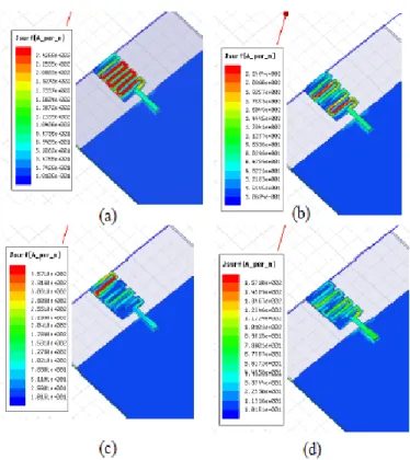
The current density of the unloaded meander antenna at all the three frequencies concentrated along the feed line and the first meandered line. The strong current density couples the high current on the floating ground plane. The capacitor was inserted at the end meander line where there is a low current density, caused the ability to draw the current, both generated frequencies can be shifted to lower frequencies while increasing the capacitances values. Fig.6 shown the current density of the antenna when the capacitance value is C=5.2pF.
Fig. 6. Simulated current density of the meander antenna for C=5.2pF at: (a) F1= 0.84, (b) F2= 1.86, (c) F3= 2.2 and (d) F4= 2.78GHz
The representation of the current density explains well the radiation property of the meander antenna for all the resonance frequencies when c=5.2pF. 3D radiation pattern has a hallow along the ox-axis. We note that we have the same radiation behavior of unloaded antenna. The simulated obtained gain presented in Fig 7, is about -0.97dBi (0.84GHz), 3.9dBi (1.86GHz), -3.4dBi (2.2GHz) and 4.12dBi (2.78GHz).
Fig. 7. Simulated 3D radiation pattern of the meander antenna for C=5.2pF at: (a) F1= 0.84, (b) F2= 1.86, (c) F3= 2.2 and (d) F4= 2.78GHz
B. Varactor diode
In order to electronically reconfigure the proposed antenna in a specific bands and achieving a large tuning frequencies range, a BB833 varactor diode from Infineon was replaced the chip capacité between the meander and the ground plane. The diode was reverse biased so requires adding a resistance, referred potential diode. It was placed under the meander, connected to the ground plane. A low pass filter was added to the antenna structure, which aims to eliminate the interference between the continuous and nonlinear. Therefore, eliminate the impact of the polarization of the diode of the antenna radiation behavior. The prototype frequency reconfigurable antenna was shown in Fig.8.
Fig. 8. Prototype of the frequency reconfigurable antenna
The measured return loss of the proposed antenna where the applied reverse voltage V rises from V=0V to V=17V (capacitor value C decreases), are shown in Figs.9. Hence, the effective electric length changes leading to the shift of antenna bandwidth to higher frequencies. We can note that, when applying a reverse voltage from 0 to 8V, only the two frequencies F1 and F2 shift to higher frequencies with a good input impedance matching. Frequencies F3 and F4 stay unchanged. Obtained tuning measured frequencies range from
0.7 to 0.98GHz for F1 and from 1.46 to 2.02 for frequency F2. When the applied voltage increases from 9 to 17V we observed that, the frequency F2 is coincident with F3 fixed at 2.02GHz and F1 stay unchanged with obtained frequency of 0.97GHz. Frequency F4 changes slightly to higher frequencies. A new frequency F5 appears with get tuning measured frequency ranges from 2.23 to 2.47GHz. This slight variation in the resonant frequencies is due to the small variation of the capacitances values of the varactor diode.
We can note that a compact multiband antenna using varactor diode was achieved with an important tuning ranges and good input impedance. All obtained measured frequencies are summarized in Table II.
Fig. 9. Measured return loss S11 for V=0 to 17V
A comparison between simulation and measured return loss when V=6V (C=2.7pF) are presented in Fig.10.
Fig. 10. Simulated and measured return loss S11 of the meander antenna for V=6V
Measured reflection coefficient agrees well with simulated results. The shift found at higher frequencies may be assigned to the fact that the varactor diode model used in simulation was simplified (losses were not taken into consideration). It is noted that the capacity value is that given by the constructor and may be different from the real value.
TABLE. II. MEASUREMENT RESONANCE FREQUENCY
V(v) C (pF) F1 (GHz) F2 (GHz) F3 (GHz) F4 (GHz) F5 (GHz) 0 - 0.7 1.46 2.03 2.75 - 3 5.3 0.84 1.63 2.04 2.77 - 6 2.7 0.91 1.88 2.05 2.77 - 8 1.8 0.95 1.9 1.98 2.78 - 9 1.5 0.97 1.98 2.01 2.81 2.23 12 0.8 0.97 2.01 2.02 2.82 2.36 14 0.76 0.98 2.02 2.02 2.84 2.4 17 0.7 0.98 2.03 2.03 2.87 2.47
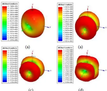
The 3D radiation patterns for the proposed antenna when V=6V, are shown in Figs.11 and 12. There is a good agreement between the simulation and the measured radiation patterns. We note that with the introduction of a varactor diode, we keep the same radiation patterns with a simple structure. Detailed of simulated and measured gains are presented in Table III.
(a)
(b)
(c)
(d)
Fig. 11. Simulated 3D radiation pattern of the meander antenna for V=6V at: (a) F1= 0.88, (b) F2= 1.9, (c) F3= 2.34 and (d) F4= 2.86GHz
Fig. 12. Simulated 3D radiation pattern of the meander antenna for V=6V at: (a) F1= 0.88, (b) F2= 1.9, (c) F3= 2.34 and (d) F4= 2.86GHz
TABLE. III. SIMULATED AND MEASURED GAIN FOR V=6V
Frequency (GHz) Gain (dBi)
Simulated Measured Simulated Measured
0.88 0.91 -0.11 -2.9 1.9 1.88 2.12 -0.88 2.34 2.05 0.24 -3.05 2.86 2.77 3.97 3.05
IV. CONCLUSION
In this paper, frequency reconfigurable meander patch antenna with compact size was studied. The resonance frequency can be controlled by inserting firstly a chip capacitor then by embedding a varactor diode. Wide tuning frequency ranges was achieved with stable radiation properties. The performance of the antenna such as, return loss and 3D radiation pattern are measured. The proposed multiband antenna can be easily integrated into PCB and it seems useful to meet wireless communication system needs. Further studies are planned to improve the performance of the antenna in terms of gain and efficiency, using the micro fluidic structure.
REFERENCES
[1] Y. Cao, S.W. Cheung , and T.I. Yuk, “Frequency reconfigurable multiple-input-multiple-output monopole antenna with wide-continuous tuning range,” IET Microwaves, Antennas & Propagation, 2016, Vol. 10, pp. 1322-1331
[2] L. Xing and Y. Huang, “A Transparent Dielectric Loaded Reconfigurable Antenna With a Wide Tuning Range,” IEEE Antennas and Wireless Propagation Letters, 2016, Vol. 15, pp. 1630-1633 [3] L. Zhou, S.K. Sharma , and S.K. Kassegne, “Reconfigurable Microstrip
Rectangular Loop Antennas Using RF MEMS Swithces,” Mirowave and Optical Technology Letters, 2008, Vol. 50, No.1
[4] A. Dey , “Microfluidically Controlled Freaquency Tunable Monopole Antenna for High Power Applications,” IEEE Antennas and Wireless Propagation Letters, 2016, Vol. 15, pp. 226-229
[5] H. Chen, C.Y. Sim , C.H. Tsai and C. Kuo, “Compact Circularly Polarized Meandered-Loop Antenna for UHF-Band RFID Tag,” IEEE Antennas and Wireless Propagation Letters, 2016, Vol. 15, pp. 1602-1605
[6] P. Bartwal, A.K. Gautam ,A. K. Singh, B.K.Kanaujia and K. Rambabu, “Design of Compact multi-band menader-line antenna for global positionning system/wireless local area network/worldwide interoperability for microwave access band applications in laptops/tablets,” IET Microwaves, Antennas & Propagation, 2016, Vol. 10, pp. 1618-1624
[7] A.Khaleghi, “Dual Band Meander Line Antenna for Wireless LAN Communication,” IEEE Transactions on Antennas and Propagation, 2007, Vol.55,PP 1004-1009
[8] A. Loutridis, M. John and M.J. Ammann, “Folded menader line antenna for wireless M-Bus in the VHF and UHF bands,” Electronics Letters, 2015, Vol.51, No.15, pp. 1138-1140
[9] C.Y.Desmond, T.Y.Han and Y.J.Liao, “A Freaquency Reconfigurable Half Annular Ring Slot Antenna Design,” IEEE Transaction on Antennas and Propagation, 2014, Vol.62,PP. 3428-3431
[10] N. Ibrahim, M.Elamin, T.Abdul Rahman, and A.Y. Abdul Rahman, “New Adjustable slot meander patch antenna for 4G handheld devices,” IEEE Antennas Wireless Propagation Letters, 2013, Vol. 12, pp. 1077-1080
[11] C.W.Jung, Y.J.Kim, Y.E.Kim and F.De Flaviis, “Macro-micro frequency tuning antenna for reconfigurable wireless communication system,” Electronics Letters, 2007, Vol.43, No.4
[12] Mohammad S. Sharawi, Yanal S. Faouri, and Sheikh S. Iqbal, “Design of an electrically small meander antenna for LTE mobile terminals in the 800 MHz band”, IEEE GCC Conference and Exhibition, February 19-22, 2011 Dubai
[13] Y.Cao,, S.W. Cheung , X.L.Sun, and T.I.Yuk, “Frequency reconfigurable monopole antenna with wide tuning range for cognitive radio,” Mirowave and Optical Technology Letters, 2014, Vol. 56, No.1