ISMRE2018/XXXX-2018 ALGERIA
Design and realization of a two axis system
designated for mini solar tower
1
stKhelifi Reski,1
st Amor Gama, 1st Belaid Abd Elfateh,1st Yettou Fatiha,1st Bezza Bedraddine, 2ndBelroul Rafika,
3
ndMostefaoui Mohammed
1st Unité de Recherche Appliquée en Energies Renouvelables, URAER, Centre de Développement des Energies Renouvelables, CDER, 47133, Ghardaïa, Algeria
2nd Laboratoire de Microélectronique Appliquée, Département d’électronique,Université Djillali Liabès de Sidi Bel-Abbes, 22000 Sidi Bel-Bel-Abbes, Algérie
3nd École Supérieure en Informatique, BP 73, Bureau de poste EL WIAM, 22016 Sidi Bel Abbés, Algérie ………
Corresponding :[email protected]
Abstract—In this work, we present a design of a mathematical model used in the simulation of the behavior of a two-axis solar tracking system (heliostats). This system is used as part of a project of a mini solar tower installed in the region of Ghardaïa. Then we start with the mechanical design of heliostats using SolidWorks software. After that, we went ahead with the realization of this system.
Keywords—solar tracking, solar tower, heliostats, SolidWorks
I. INTRODUCTION
The solar power tower (SPT) is one the systems to produce electricity by use concentrated solar radiation to generate high temperatures, which are later employed to drive a conventional power cycle and produce electricity [1]. In SPT the concentration of the solar radiation performed by mechanical systems namely heliostats. Heliostats are mirrors positioned around the tower, every one of them carried by metallic structure and oriented by two drives.
Heliostats typically contribute about 40% to the total cost of the solar power tower plants [2],[3]. Therefore, the choice of the structural design of the heliostats is important for the low-cost SPT installation.
Our work consists of designing a mathematical model that allows the calculation the position of heliostat field and conception realization the systems (heliostat).
II. MATHEMATICAL MODEL
The position of the sun relative to a point on Earth's surface is defined by two angles:
The sun altitude (h) is the angle between the direction of the sun and the horizontal plan on earth (3).
)
sin(
)
sin(
)
cos(
)
cos(
)
cos(
)
sin(
h
(1) δ: declination angle. φ: location latitude. ω: hour angle.The sun Azimuth (a): This is the angle between the projection of the direction of the sun on the horizontal plane and the south (3).
) cos( ) sin( ) cos( ) sin( h Az
(2) The sun position vector Sun is presented by thefollowing equation:
)
sin(
)
cos(
*
)
sin(
)
cos(
*
)
cos(
_
_
_
H
H
Az
h
Az
Z
Sun
E
Sun
S
Sun
sun
(3)A. Radiation reflected by the optical system
Fig. 1. The different vectors of the optical system
According to Figure 1. Calculating the MT vector is possible if the coordinates of the points M and T are known, with:
)
,
,
(
M M M MS
E
H
Cord
(4))
,
0
,
0
(
_TH
TCord
(5) HM=1.5m, H_T=7.5 mM : Represent the center point of the heliostat T : Represent the fixed point in the solar tower The MT vector will be calculated from the expression
-1500 -1000 -500 0 500 1000 1500 600 900 1200 1500 1800 2100 2400 (So u th) Y Pos ition [m] ( N o rth )
(West) X Position [m] (East)
)
,
,
(
S
ME
MH
TH
MMT
(6)The normal Vector of the heliostat
The normal vector of a heliostat must be the sum vector of the reflected sunrays unit vector and a unit vector that is from the center heliostat toward the fixed-point (the solar tower).Fig.2.
This vector is given by the following expression:
U
Sun
U
MT
N
_ _ (7) U_Sun : Unit sun vectorU_MT: Unit vector of the direction of MT
Fig. 2. Component of the N vector
In a system, SEZ fixed to the Earth, the components of the vector N is given by the following formula:
)
sin(
)
cos(
*
)
sin(
)
cos(
*
)
cos(
_
_
_
inc inc Az inc Azz
N
e
N
s
N
N
(8)From this expression the calculation of angles of rotation of vector N is given by the following relation:
)
,
arctan(
N
SN
_E
Az
(9))
,
arctan(
_ 2 2 _S
N
E
N
N
z Az
(10)θAz : azimuth rotation angle of heliostat.
θinc : incline rotation angle of heliostat.
III. BOUNDARY OF THE HELIOSTATS FIELD
A C++ code has been developed to obtain a
preliminary distribution of the land efficiency available on a 460 m surface with a latitude of 32º N [5]. The main parameters used are given in Table 1.
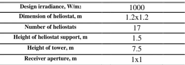
TABLE I. DISCRIPTION OF THE FIELD.
Design irradiance, W/m2 1000
Dimension of heliostat, m 1.2x1.2 Number of heliostats 17 Height of heliostat support, m 1.5 Height of tower, m 7.5 Receiver aperture, m 1x1
IV. CONFIGURATION OF THE HELIOSTATS FIELD
The designed heliostats field for the scale of 25kW solar power tower plant is shown in Fig.3.
Fig. 3. Layout of the heliostats field V. PERFORMANCE OF SYSTEM
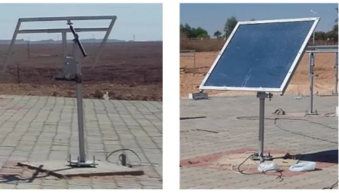
Using the SolidWorks software [4], we have carried out the design of a prototype heliostat (height of 1.5 m and mirror of 1,2 x 1,2m). The purpose of this design achieved an autonomous system to a motorized support by two direct current motors has two degree of freedoms of type (Azimuth/Altitude), having the function to guide and align a mirror facing the sun while in the long run of the day. This system been manufactured to the unit of applied research for renewable energies (URAER), Ghardaïa, in Algeria. Fig.4.
Based on the results of the design and simulation, we have made of this system. Fig.5 After the installation of the heliostat in the solar field (solar tower) and the application of the electronic control system, the heliostat showed a remarkable degree of accuracy and a good functioning.
Fig. 5. The realized design heliostat.
- The Heliostats have been designed and manufactured for the mini test installation of the tower of solar power the unit of applied research for renewable energies (URAER), Ghardaïa, in Algeria. The field of heliostat is newly built; it has 17 heliostats and a tower height of 7.5 m, as shown in the Fig. 6. The heliostats are described below.
Fig. 6. Installation of the heliostats and test VI. CONCLUSIONS
The heliostats and small reflective zone were designed and manufactured for a mini solar power test tower installation of the Applied Research Unit for Renewable Energies (URAER), Ghardaïa, Algeria. We use a mathematical model to position the heliostats on the terrain with a surface area of 460 m and a tower height of 7.5 m. The main objective of this article is the design and realization of the 17 heliostats for the Ghardaïa zone.
REFERENCES
[1] A. Ferrière. “Centrales solaires thermodynamiques. Edition Techniques de l’Ingénieur”, BE 8 903, pp 1-20, 2007.
[2] S.Bonnet, M. Alaphilippe, P. Stouffs. “Thermodynamic solar energy conversion: Reflections on the optimal solar concentration ratio”. International Journal of Energy, Environment and Economics,vol 12, pp141-152., 2006.
[3] M. Capderou, Atlas solaire de l’Algerie, Tome. 2, OPU, 1986. [4] SolidWorks, SolidWorks Corporation, 300 Baker Avenue, Concord,
MA 01742. Available from: http://www.solidworks.com/
[5] F.M.F.Siala and M.E.Elayeb, “Mathematical formulation of a graphical method for a no-blocking heliostat field layout”, Renewable Energy, vol.23, 2001, pp77-92.
[6] Forman, G. An extensive empirical study of feature selection metrics for text classification. J. Mach. Learn. Res. 3, 1289-1305, March 2003.