HAL Id: hal-02130100
https://hal.archives-ouvertes.fr/hal-02130100
Submitted on 15 May 2019
HAL is a multi-disciplinary open access
archive for the deposit and dissemination of
sci-entific research documents, whether they are
pub-lished or not. The documents may come from
teaching and research institutions in France or
abroad, or from public or private research centers.
L’archive ouverte pluridisciplinaire HAL, est
destinée au dépôt et à la diffusion de documents
scientifiques de niveau recherche, publiés ou non,
émanant des établissements d’enseignement et de
recherche français ou étrangers, des laboratoires
publics ou privés.
Thermal Analysis for Wound-Rotor Synchronous
Machine
Shinara Utegenova, Frédéric Dubas, Michel Jamot, Raynal Glises, Bertrand
Truffart, Damien Mariotto, Patrick Lagonotte, Philippe Désévaux
To cite this version:
Shinara Utegenova, Frédéric Dubas, Michel Jamot, Raynal Glises, Bertrand Truffart, et al.. An
Inves-tigation into the Coupling of Magnetic and Thermal Analysis for Wound-Rotor Synchronous Machine.
IEEE Transactions on Industrial Electronics, Institute of Electrical and Electronics Engineers, 2018,
65 (4), pp.3406 - 3416. �hal-02130100�
Abstract—This paper is dealing with magnetic and thermal
analysis coupling of wound-rotor synchronous machine (WRSM) based on the equivalent circuit methods. The main objective of this work is to introduce the principles of both magnetic equivalent circuit (MEC) and thermal equivalent circuit (TEC) models, as well as the importance of their coupling. The results of nonlinear MEC are compared to two-dimensional (2-D) finite-element analysis (FEA) results obtained by the magnetic field analysis software JMAG. While the results of TEC coupled with MEC are compared with the experimental thermal test results.
Index Terms—Coupling, equivalent circuit, experimental,
magnetic, numerical, thermal.
I. INTRODUCTION
A. Context of this Paper
OWADAYS, the electric propulsion system enters intensely in the aerospace world. The machine technologies are compared in the context of their performances, dimensions and ability to satisfy the specific safety requirements [1]. Application of electrical propulsion in helicopters particularly imposes high performance requirements as well as dimension and thermal constraints. Thus, the magneto-thermal analysis becomes very important for electrical machine design process as its magnetic and thermal behaviour depends on one another.
The importance of magnetic and thermal analysis coupling was discussed by many authors. This type of coupling using FEAs is one of the most conventional and precise solutions [2]-[5]. Coupling of magnetic FEA and computational fluid dynamics analysis [6]-[7] is another widely used option, permitting to predict fluid behavior inside and outside the machine, which is quite difficult, as it depends on machine geometry, means of cooling, machine rotational speed, etc. However, all these high-performance numerical analyses could lead to an extremely high, sometimes unreasonable time cost. In order to reduce the computational time, the results of magnetic FEA are often coupled to analytical TEC analysis [8]-[11]. Moreover, several commercial softwares propose coupling of magnetic FEA and automatic TEC (e.g., Manuscript received April 04, 2017; revised July 25, 2017; accepted September 03, 2017.
Sh. Utegenova, F. Dubas, R. Glises and Ph. Desevaux are with the Département ENERGIE, Univ. Bourgogne Franche-Comté, F90000 Belfort, France (e-mail: fdubas@gmail.com).
MotorCAD) [12]-[13]. Nevertheless, FEA still remains a highly time consuming numerical simulation.
In case, if a fast but an accurate prediction of electrical machine’s magneto-thermal behavior is needed, a MEC and TEC coupling could be a better choice. Some recent studies propose such coupling for surface-mounted permanent-magnet (PM) machines without giving any details [14]. In [15], the authors performed a MEC and TEC coupling for WRSM. They assumed that the flux densities inside the machine are sinusoidal and calculated the iron losses using Bertotti’s formula [16], whereas electric machines can have very different flux density waveforms. It is interesting to notice that an overview of existing models of iron loss identification was done in [17], where authors propose a new method of iron loss prediction by using a precise hysteresis model based on the magnetic flux density waveforms resulting from a MEC.
To the authors' knowledge, and basing on this brief state-of-art on coupling analysis, there is a lack of magneto-thermal semi-analytical analysis (based on equivalent circuits) in electrical machines for purpose of a design optimization process with experimental validation.
B. Objectives of this Paper
In this paper, a precise determination of flux densities distribution inside the machine using MEC serve to calculate the iron losses basing on fast Fourier transform (FFT) and iron loss property curves of electromagnetic steel sheets given by manufacturer. The calculated loss permit to complete TEC with the heat sources values. TEC takes into account variation of material properties with the temperature inside the machine, such as copper resistivity, cooling fluid and bearings grease thermal properties, etc. Therefore, the main objective of this paper is the investigation of the coupling of MEC and TEC models on an example of WRSM.
Section II describes the main principles and general assumptions of both MEC and TEC. Particularly, 2-D auto-adjustable mesh principle for MEC and three-dimensional (3-D) TEC taking into account forced cooling of an open machine with axial cooling channels inside stator yoke. Moreover, the magnetic loss identification using MEC results and the principle of MEC and TEC coupling have been discussed in this section. Section III Sh. Utegenova, M. Jamot, B. Truffart and D. Mariotto are with Airbus Helicopters, 13700 Marignane, France (e-mail: damien.mariotto@airbus.com)
P. Lagonotte is with the Fluids, Thermal and Combustion Sciences Department, University of Poitiers, 86073 Poitiers, France (e-mail: patrick.lagonotte@univ-poitiers.fr)
Sh. Utegenova, F. Dubas, M. Jamot, R. Glises, B. Truffart,
D. Mariotto, P. Lagonotte and Ph. Desevaux
An Investigation into the Coupling of Magnetic
and Thermal Analysis for Wound-Rotor
Synchronous Machine
presents the MEC results are compared to those of FEA, and the TEC results coupled with MEC are compared to the experimental test results carried out on a particular WRSM.
The results comparison obtained by the coupled models with FEA and experimental tests has confirmed the validity of the coupling approach. The computation time obtained with this coupling approach has been compared to FEA.
II. SEMI-ANALYTICAL MODELS
A. Magnetic Equivalent Circuit
The MEC approach was first introduced in 1940's by Roters [18], which has defined the basic principles of MEC in electromagnetic devices. Since many researchers have improved this method [19]-[21], viz., saturation effect, PM magnetization direction, MEC discretization,…, rotor motion. MEC is based on the magnetic flux tubes method, where the flux paths are approximated to a set of connected tubes. The magnetic reluctance of a flux tube depends on its geometry details and relative permeability of its material. The magnetomotive forces (MMFs) created inside the machine are dependent on the current waveform (e.g., sinusoidal, six-step rectangular, pulse-width modulation currents, etc) and of the coils spatial distribution.
1) Assumptions
The main assumptions used in nonlinear adaptive MEC are: - semi-analytical model is supposed 2-D;
- end-effects are neglected;
- eddy-current reaction field in all materials (e.g., the copper, and the iron) is neglected;
- magnetic materials are considered as isotropic; - mechanical stress on the B(H) curve is ignored; - hysteresis effects are ignored;
- current waveform is supposed sinusoidal. 2) Main Principle of 2-D Nonlinear Adaptive MEC
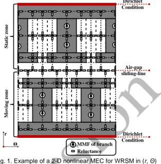
Generalized nonlinear adaptive MEC, applied in this study, was presented in [22]. This semi-analytical model includes the automatic mesh of static/moving zones, the saturation effect, and zones connection in accordance with rotor motion, which is based on a new approach called “Air-gap sliding-line technic”, which was applied in [23]-[26] on different electrical machine configurations (i.e., axial- and radial-flux interior PM machine and coaxial magnetic gear equipped with surface-mounted PMs). This new technic of connection between static/moving zones is applied for the first time on a WRSM in this paper. Nevertheless, it should be noted that there are other techniques permitting to connect static/moving zones in electrical machines, which have been overviewed in [22].
Fig. 1 represents a generalized 2-D MEC discretization example for a WRSM in (r, Θ) coordinate system. The machine is divided into two zones: static and moving. The zone discretizations are independent. The connection between zones is insured by air-gap tangential reluctances that vary with motion. Tangential and radial discretizations are also independent and could be adjusted automatically in function of demanded precision [22].
The analytical expressions of radial and tangential reluctances were given by [25]:
𝑅𝑟𝑖(𝐵𝑟𝑖) = 1 𝜇0∙ 𝜇𝑟(𝐵𝑟𝑖) ∙ 𝐿 ∙ 1 𝛩𝑖∙ ln ( 𝑅𝑜𝑢𝑡𝑖 𝑅𝑖𝑛𝑖 ) (1) 𝑅𝛩𝑖(𝐵𝛩𝑖) = 1 𝜇0∙ 𝜇𝑟(𝐵𝛩𝑖) ∙ 𝐿 ∙ 𝛩𝑖∙ 1 ln (𝑅𝑜𝑢𝑡 𝑖 𝑅𝑖𝑛𝑖 ) (2)
where 𝜇0 is the vacuum permeability; 𝐿 is axial length of the
machine; 𝐵𝑟𝑖 and 𝐵𝛩𝑖 are respectively radial and tangential
components of magnetic flux density; 𝛩𝑖 is opening angle of
reluctance i; 𝑅𝑖𝑛𝑖 and 𝑅𝑜𝑢𝑡𝑖 are respectively inner and outer radius
of the reluctance i; 𝜇𝑟(∎) is the relative permeability defined by:
𝜇𝑟(∎) = {
𝐵(𝐻)curve 1
in the iron parts in the vacuum
(3)
The iron relative permeability are obtained by interpolating flux density values using B(H) curve provided by iron manufacturer.
As in case of a WRSM there are no other MMF sources than those generated by currents circulating in stator and rotor windings. The MMFs could be expressed by:
where 𝑁𝑖 is the number of coil turns, and 𝑖𝑖(𝑡) supply current (viz.,
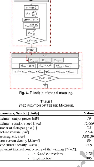
alternative and continuous for stator and rotor respectively). It should be noted that the flowchart of the nonlinear adaptive MEC is illustrated in Fig. 6.
3) Magnetic Loss Estimation
Once, the waveforms of the magnetic flux density in each reluctance are obtained by 2-D nonlinear MEC, an iron loss estimation of each flux tube could be carried out. The principle
Fig. 1. Example of a 2-D nonlinear MEC for WRSM in (r, Θ) coordinate system. 𝑀𝑀𝐹𝑖= 𝑁𝑖∙ 𝑖𝑖(𝑡) (4) r Θ Sta tic zone Movin g zone Air-gap sliding-line Dirichlet Condition Dirichlet Condition MMF of branch Reluctance
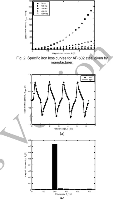
of iron loss calculation applied in this study is based on the specific iron loss 𝑃𝑠𝑝𝑒𝑐 curves of the materials given by
manufacturer. An example of such curves is given in Fig. 2. The characteristic losses are obtained by applying a sinusoidal magnetic flux with specific values of peak flux density and frequency. As it was already mentioned, the magnetic flux density inside the machine is rarely sinusoidal. So the main idea is to decompose non-sinusoidal magnetic flux density 𝐵𝑀𝐸𝐶
obtained by MEC into a set of its sinusoidal components 𝐵𝑖
corresponding to different frequencies 𝑓𝑖 using FFT:
𝐵
𝑀𝐸𝐶= ∑ 𝐵
𝑖∙ 𝑒
−𝑗∙𝜔𝑖∙𝑡 𝑘𝑖=1
for each reluctance, (5)
where 𝑘 is number of angular frequencies 𝜔𝑖= 2𝜋 ∙ 𝑓𝑖 taken
into account, and 𝑡 is time coordinate. Fig. 3(b) represents an example of such FFT decomposition of non-sinusoidal magnetic flux density in the center of the stator tooth for WRSM shown in Fig. 3(a).
Then obtained magnetic flux density and frequency values are used to interpolate/extrapolate the total loss values from the specific iron loss curves:
𝑃𝑖= ∑ 𝑃𝑠𝑝𝑒𝑐(|𝐵𝑖|, 𝑓𝑖) 𝑘
𝑖=1
for each reluctance. (6)
B. Thermal Equivalent Circuit
The used TEC approach is an analysis of transient heat conduction/convection and mass transfer. The radiation is considered as neglectable. It’s applicable if the temperature variation within the medium can be neglected and the temperature is considered to be a function of time only [27]. An electrical machine represents a strong thermal heterogeneity, because of different materials constituting it. However, its geometry is regular, and having many symmetries, often it could be reduced to a set of geometries of simple shapes, permitting to apply TEC. Moreover, a relatively low discretization comparing to MEC could be sufficient for a quite precise thermal analysis [28]. Passing from 2-D to 3-D analysis disables the auto-adjustment of the model discretization. However, in the case of TEC, this fact is not critical. A more detailed description of TEC architecture could be found in [29].
1) Assumptions
The main assumptions used in transient TEC are: - semi-analytical model is supposed 3-D;
- simplified geometry definition and dividing of the machine into a set of elementary blocks;
- uniform temperature distribution within each node; - homogenous heat distribution in the entire volume of
each node;
- uniform material characteristics for each node; - Neumann’s boundary condition allowing the
assumption of surface temperatures uniformity.
Fig. 2. Specific iron loss curves for AF-502 steel given by manufacturer.
(a)
(b)
Fig. 3. Example of magnetic flux density in the center of the stator tooth for WRSM obtained by 2-D nonlinear MEC: (a) Waveform,
and (b) Harmonic spectrum.
2) Main Principle of 3-D Transient TEC
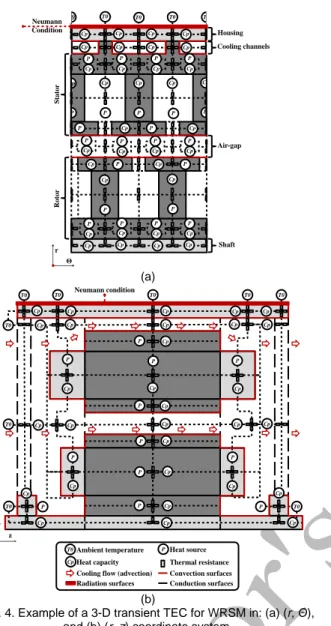
First of all, different heat transfer modes between the regions of the machine have to be identified. The regions are defined by the nature of their materials and the thermal exchange mode between them. In 3-D transient TEC each region could exchange energy with six neighboring regions by the means of three heat transfer modes (i.e., conduction, convection, and radiation heat transfer) or by the mass transfer (i.e., advection) [30]. The dominant processes in heat transfer within the motor to the environment are conduction and convection, whereas radiation is important only on the outer surfaces [31]. Fig. 4 represents an example of TEC discretization in (r, Θ) [see Fig. 4(a)] and (r, z) [see Fig. 4(b)] coordinate system for a WRSM. Presented machine is equipped by an external fan, which permits to ensure a forced cooling of the machine through the air-gap and the axial cooling channels inside stator yoke. Such channels are widely used for an improvement of electrical machine’s cooling system [32]-[34]. 0 0.5 1 1.5 2 0 50 100 150 200 250 300 350 400
Magnetic flux density, B [T]
S p e ci fi c ir o n l o sse s, Ps p e c [ W /kg ] 50 Hz 100 Hz 200 Hz 400 Hz 1000 Hz 0 1 2 3 4 5 6 7 -1.5 -1 -0.5 0 0.5 1 1.5 M a g n e ti c fl u x d e n si ty, B M E C [ T ]
Rotation angle, [rad]
MEC FFT 0 100 200 300 400 500 0 0.1 0.2 0.3 0.4 0.5 0.6 0.7 0.8 M a g n e ti c fl u x d e n si ty, B i [ T ] Frequency, f i [Hz]
Conduction Heat Transfer: It presumes a heat transfer by molecular interaction, when molecules at higher energy level release energy for adjacent molecules at a lower energy level [35]. Conduction is a heat transfer mode between two solids. Fourier’s law gives the heat flow transferred by conduction:
𝛷𝑐𝑜𝑛𝑑𝑖𝑗 = −𝜆𝑖∙ 𝑆𝑖𝑗∙ 𝛻𝑇 (7)
where 𝛷𝑐𝑜𝑛𝑑𝑖𝑗 is the heat flow from solid i to solid j, 𝜆𝑖 the
thermal conductivity of solid i, 𝑆𝑖𝑗 the heat transfer surface
between solids i and j, and ∇𝑇 the temperature gradient. It has to be mentioned that some regions of electrical machines (i.e., laminated core and windings) are thermally anisotropic. The presence of insulators and bonding layers reduces considerably the thermal conductivity of such regions in different directions. For the end-windings region, it is possible to provide a heat conduction path from the inner copper turns to the lamination stack by varnishing it [36]. The equivalent thermal conductivities for winding region could be determined by the approaches proposed in [37]-[38], and for laminated core by [39]-[40].
As thermal resistance depends on a ratio of temperature gradient
of a particular region over the heat rate caused this gradient, the thermal resistance of conduction could be found by:
𝑅𝑐𝑜𝑛𝑑𝑖 =
𝛻𝑇 𝛷𝑐𝑜𝑛𝑑𝑖𝑗 =
1
𝜆𝑖∙ 𝑆𝑖𝑗 (8)
Convection Heat Transfer: It is defined as the heat transfer between a region of higher temperature (here, a solid surface) and a region of cooler temperature (a coolant) resulting from the motion of the cooling fluid over the solid surface. This motion is particularly difficult to predict and to take into account. In order to facilitate this task, there are many empirical correlations proposed in literature permitting to estimate heat transfer coefficient values in different regions of the machine.
Thus, the influence of the form of the cooling channels have been studied by many authors [41]-[42]. One of such works has been done by [31]. The author proposes to identify the heat transfer coefficient that takes into account the geometry of the channels and the parameters of the cooling flux:
ℎ𝑐ℎ𝑎𝑛= 104∙ 𝜌𝑎𝑖𝑟∙ 𝑐 𝑝𝑎𝑖𝑟∙ 𝑉𝑐ℎ𝑎𝑛∙ 𝐷ℎ 4 ∙ 𝐿𝑐ℎ𝑎𝑛 ∙ (1 − 𝑒−𝐸) (9a) 𝐸 = 0.15 ∙𝐿𝑐ℎ𝑎𝑛 0.946 𝐷ℎ1.16 ∙ ( 𝜆 𝑎𝑖𝑟 𝜌𝑎𝑖𝑟∙ 𝑐 𝑝𝑎𝑖𝑟∙ 𝑉𝑐ℎ𝑎𝑛 ) 0.214 (9b)
where 𝑉𝑐ℎ𝑎𝑛, 𝐿𝑐ℎ𝑎𝑛 and 𝐷ℎ are respectively the velocity of the
cooling flow inside the channels, the axial length of one channel, and the hydraulic diameter.
The fluid flow in the air-gap is quite difficult to model analytically. There are a lot of research works that deal with this problem [31] and [43]-[44]. It becomes more complicated in case of an open machine with forced cooling [45]. For our study, the empirical approach proposed by [42] has been chosen. The author studies experimentally and numerically the stator/rotor slotting effect on the convection inside the air-gap with(out) forced cooling through it:
ℎ𝑎𝑖𝑟−𝑔𝑎𝑝= 𝑁𝑢 ∙ 𝜆𝑎𝑖𝑟⁄ 𝛿 (10)
where δ is air-gap length of the machine, and 𝑁𝑢 is Nusselt number dependent on effective Reynold number 𝑅𝑒𝑒𝑓𝑓 could
be identified by:
𝑁𝑢 = 0.021 ∙ 𝑅𝑒𝑒𝑓𝑓0.8 (11a)
𝑅𝑒𝑒𝑓𝑓= 2 ∙ 𝜌𝑎𝑖𝑟∙ 𝑉𝑒𝑓𝑓∙ 𝛿 𝜇⁄ 𝑎𝑖𝑟 (11b)
𝑉𝑒𝑓𝑓 = √𝑉𝛿2+ 𝛼 ∙ (𝜔 ∙ 𝐷𝑟𝑚𝑎𝑥⁄ )2 2 (11c)
where 𝑉𝛿 is axial velocity of cooling flow entering the air-gap,
Fig. 5. Sudden expansion principle. (a)
(b)
Fig. 4. Example of a 3-D transient TEC for WRSM in: (a) (r, Θ), and (b) (r, z) coordinate system.
Ambient temperature Heat capacity
Heat source Thermal resistance Cooling flow (advection)
P Cp T0 Convection surfaces Conduction surfaces Radiation surfaces T0 T0 r Θ Sta tor Roto r Housing Cooling channels Air-gap Neumann Condition Shaft T0 T0 T0 Cp Cp Cp Cp Cp Cp Cp Cp Cp Cp Cp P P P P Cp P Cp Cp P Cp P Cp P Cp P Cp P Cp P Cp P Cp P Cp P Cp P Cp P Cp Cp Cp Cp Cp P Cp P Cp P Cp P Cp P Cp P Cp P Neumann condition r z T0 Cp T0 T0 T0 T0 T0 T0 T0 Cp Cp Cp Cp Cp Cp Cp Cp Cp Cp Cp Cp Cp Cp Cp Cp Cp Cp Cp Cp Cp Cp Cp Cp Cp T0 P P P P P P P P P P Cp P P Cp Cp Cp
𝜔 is angular speed of the rotor having outer diameter 𝐷𝑟𝑚𝑎𝑥, and
𝛼 is a coefficient permitting to take into account the rotation effect on the heat transfer (with 𝛼 = 0.25 for the stator surface and 𝛼 = 0.5 for the rotor surface).
The heat transfer coefficient of the stator end-winding region identification is very delicate, because its geometry is irregular and the heating of the zone is non-uniform. There are a lot of studies proposing empirical correlations based on CFD analysis of different closed machine typologies [33], [40], [44], [46]-[48]. In case of an open machine with forced axial cooling, the cooling flux is predominant around the front side end-windings [49]. That is why the transverse surfaces of this region could be represented by an impinging jet on a static surface. In that case the heat transfer coefficient could be defined by [50]:
𝑁𝑢 = 0.698 ∙ 𝑅𝑒0.573∙ (𝐻 𝐷⁄ )−0.116 (12)
where 𝐷 is the diameter of the surface impacted by the jet positioned at a distance 𝐻 from its source.
The surfaces of rear side stator end-winding region are not exposed directly to the cooling flow, but to the sudden flow expansion [see Fig. 5]. The heat transfer coefficient for this region could be found by estimation of an equivalent speed from the kinetic energy loss due to the expansion [33] and [51]:
𝑃𝑘𝑖𝑛= 𝑅 ∙ 𝑄2 (13a)
𝑅 = 0.5 ∙ 𝑘 ∙ 𝜌𝑎𝑖𝑟 𝑆 1
⁄ (13b)
𝑘 = (1 − 𝑆1⁄ )𝑆2 2 (13c)
where 𝑅 is the flow resistance; 𝑄 is the mass flow rate; 𝑆1 and 𝑆2
are respectively the cross sections of the conduit before and after expansion as shown in Fig. 5.
The rotor end-winding region is also very difficult to model precisely. However, due to the high speed of rotation and axial cooling air-flow, this region could be represented by an impinging jet to a rotating disk. Thus, the heat transfer coefficient of the front side rotor end-winding zone defined by 𝑁𝑢 could be determined by [52]: 𝑁𝑢 = 𝑅𝑒Θ0.5∙ { (0.33 + 1.57 ∙ 𝜉) 1.81 ∙ 𝜉0.597 for 𝜉 < 1 for 𝜉 < 1 (14a) 𝜉 = 𝑅𝑒𝑎∙ ( 𝑉𝑎 𝜔 ∙ 𝑧2) 3/4 (14b) 𝑅𝑒Θ= 0.5 ∙ 𝜌𝑎𝑖𝑟∙ 𝜔 ∙ 𝐷𝑟𝑚𝑎𝑥2⁄𝜇𝑎𝑖𝑟 (14c)
where 𝑅𝑒Θ is tangential Reynold number, and 𝜉 is an empirical
coefficient with 𝑅𝑒𝑎 axial Reynold number, 𝑉𝑎 axial cooling
flow velocity, ω rotor angular velocity, and 𝑧 distance between the source of cooling flow and rotor surface.
The heat transfer coefficient of the rear side rotor end-winding, which is not directly exposed to the axial cooling flow, could be found by [44]: 𝑁𝑢 = 0.5 ∙ 𝑃𝑟 ∙ 𝑅𝑒Θ∙ 𝐶𝑚⁄ 𝜋 (15a) 𝐶𝑚= { 3.87 𝑅𝑒⁄ Θ0.5 0.146 𝑅𝑒⁄ Θ0.2 for 𝑅𝑒Θ< 3 ∙ 105 for 𝑅𝑒Θ> 3 ∙ 105 (15b)
Once the main heat transfer coefficients of the machine are defined, thermal resistance of convection could be found by:
𝑅𝑐𝑜𝑛𝑣𝑖 =
1
ℎ𝑖∙ 𝑆𝑖 (16)
where ℎ𝑖 is the convention coefficient on the solid surface 𝑆𝑖.
Cooling Flow-Network Analysis: As the main part of the heat generated inside the radial-flux electrical machine evacuates radially, externally forced axial cooling flow permits to remove a significant part of this heat. Created fluid flow rate could be represented by a transport of mass which direction introduces non-symmetric matrix of thermal resistances by advection [53]:
𝑅𝑎𝑑𝑣𝑒𝑐𝑖𝑗 = { 1 𝑄𝑖𝑗∙ 𝜌𝑖∙ 𝑐𝑝𝑖 0 if 𝑄𝑖𝑗> 0 otherwise (17)
where 𝑄𝑖𝑗 is fluid flow rate from region 𝑖 to region 𝑗, 𝜌𝑖 and 𝑐𝑝𝑖
are respectively the fluid density and the specific heat capacity. C. Model Coupling: MEC and TEC
Once the thermal resistances matrix and boundary conditions of the machine are defined, TEC has to be completed by the heat flux values generated inside the machine. It has to be reminded that there are three main families of electrical machine losses, viz.,
- DC resistive losses in the stator and rotor winding; - magnetic losses in ferromagnetic material; - friction losses (e.g., mechanical and windage). It has to be mentioned that AC resistive losses of stator and rotor windings are not taken into account in this study. However, it is still interesting to note that [55] proposes analytical solutions permitting to calculate the skin and proximity effect losses in round conductors. A detailed loss identification, except magnetic losses, is not discussed in this paper. The DC resistive losses in the stator and rotor windings vary with temperature, as the electrical resistances of windings depend on their temperature via the electrical conductivity. The characteristics of fluid around the machine parts and those of grease inside the bearings are temperature dependent, making the friction losses temperature dependent as well. In case of a WRSM, which is the case of our study, magnetic losses remain independent of thermal state of the machine parts. So the magnetic losses could be directly introduced in TEC as it is shown in Fig. 6. Nevertheless, it should be noted that in case of a PM machine, magnetic losses obtained by 2-D nonlinear adaptive MEC could vary with temperature due to the electromagnetic properties of PMs. In that case there has to be a loop between losses calculation and 3-D transient TEC.
Fig. 6. Principle of model coupling. TABLE I
SPECIFICATION OF TESTED MACHINE.
Parameters, Symbol [Unity] Values
Maximum output power [kW] 10
Maximum rotation speed [rpm] 12,000
Number of slots per pole [–] 7.5
Machine volume [cm3] 2,500
Ferromagnetic steel AFK 502 Stator current density [A/mm²] 50 Rotor current density [A/mm²] 0.09 Equivalent thermal conductivity of the winding [W/mK]:
- in -and r-directions 0.28 - in z-direction 386
III. RESULTS AND DISCUSSIONS
A. Tested machine description
For the validation of the developed models and their coupling an open WRSM with forced cooling has been chosen. This WRSM is integrated on board of a helicopter (i.e., 10 kW @ 12,000 rpm) and has to provide relatively high-power, and as a consequence a high electrical load (i.e., the stator current density ≥ 50 𝐴 𝑚𝑚⁄ 2), during a short functioning time. The
main characteristics of this machine are shown in Table I. Due to confidentiality reasons geometrical details as well as experimental test bench could be introduced in this paper. B. Comparison between the MEC and FEA Results 1) Introduction
As 3-D transient TEC depends on 2-D nonlinear adaptive MEC, the results of magnetic analysis have to be validated first. The thermal tests that have been carried out, did not include the measurement of the magnetic flux inside the machine. The main goal of the experimental tests was to ensure that no overheating of the hottest point of the machine (stator winding) occurs. That is why the no-load tests, permitting experimental identification of losses, was not carried out. The tested machine was instrumented by 4 thermistors placed in the front/rear side of the end-windings, inside a stator slot and near the cooling airflow outlet. An insufficient number of thermal sensors did not permit to carry out
the loss separation method based on inverse technique either. Thus, the results of 2-D nonlinear adaptive MEC (viz., magnetic flux density waveforms and magnetic losses) are compared to 2-D FEA results obtained by the magnetic field analysis software JMAG with the same assumptions as equivalent circuit approach for the operating point corresponding to 5 kW @ 6,000 rpm.
2) Results Discussion
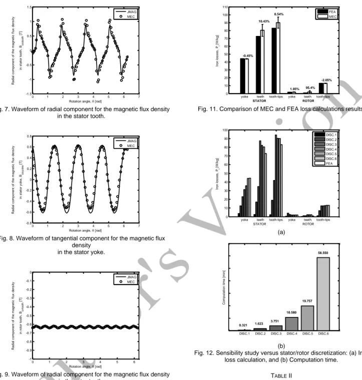
Magnetic Flux Density Distribution: It has been calculated in different parts of the tested WRSM. The waveforms of the magnetic flux density in the stator/rotor yoke and teeth are represented in Figs. 7–10. These flux densities are compared with 2-D FEA at the operating temperature equal to 125 °C. It is interesting to note that the magnetic flux density distributions are non-sinusoidal (e.g., see Fig. 7). A good correlation of the results confirms the reliability of the proposed method for magnetic flux density calculation. The precision of the magnetic analysis is very important for an accurate magnetic loss analysis, as it influences directly the thermal behavior of the electrical machine.
Magnetic Loss Distribution: Once the magnetic flux density waveforms were identified for all the active parts of the WRSM, the magnetic loss model described earlier was compared to results of 2-D FEA [see Fig. 11]. The machine ferromagnetic parts were subdivided into six zones: yoke, teeth and tooth-tips for the stator/rotor. The mean values of iron losses for each zone were identified. Regardless of the modeling technique, the rotor iron losses are much less that those of stator. That could be explained by the fact that the rotor frequency is slip times the supply frequency. In case of a synchronous machine, this frequency tends toward zero. Exposed directly to the rotating magnetic flux, the tooth-tips carry the maximum of heat generation. A quite important error of MEC for rotor has almost no influence on thermal behavior of the machine as the nominal value of rotor iron loss is almost negligible comparing to stator. Most of the time, 2-D nonlinear adaptive MEC overestimates the heat generation values for both stator and rotor. The difference between the values obtained numerically and analytically could be explained by the fact that the mesh of 2-D FEA is finer than this of 2-D nonlinear adaptive MEC and the interpolation/extrapolation method used in MEC differs from the method used in JMAG which is based on Bertotti’s formula with estimated coefficients.
Presented results correspond to a MEC with a tangential discretization equal to 3 for both stator rotor, and radial discretization equal to 3 and 7 for stator and rotor respectively. This means that one stator tooth, for example, is represented by 9 nodes. In order to reduce the difference between numerical and analytical results, the discretization of 2-D nonlinear adaptive MEC has to be increased. The influence of spatio-temporal discretization quality on the iron loss calculation accuracy has been investigated by a sensibility study. The scenarios of discretization modification are regrouped in Table II. The results of this study represented in Fig. 12 show that a finer discretization considerably improves the accuracy of the iron loss identification. At the same time the increasing of the discretization expands drastically the time of calculation, especially in case of a machine with a small geometrical periodicity.
Fig. 7. Waveform of radial component for the magnetic flux density in the stator tooth.
Fig. 8. Waveform of tangential component for the magnetic flux density
in the stator yoke.
Fig. 9. Waveform of radial component for the magnetic flux density in the rotor tooth.
Fig. 10. Waveform of tangential component for the magnetic flux density in the rotor yoke.
Fig. 11. Comparison of MEC and FEA loss calculations results.
(a)
(b)
Fig. 12. Sensibility study versus stator/rotor discretization: (a) Iron loss calculation, and (b) Computation time.
TABLE II
MECSENSIBILITY STUDY SCENARIOS.
Name Stator discretization -axis r-axis Rotor discretization -axis r-axis Rotation step
DISC.1 1 1 1 1 6.25 ∙ 10−4s DISC.2 2 1 2 1 3.12 ∙ 10−4s DISC.3 2 2 2 2 3.12 ∙ 10−4s DISC.4 3 3 3 3 2.08 ∙ 10−4s DISC.5 3 3 5 3 6.25 ∙ 10−5s DISC.6 3 3 7 3 4.46 ∙ 10−5s
C. Comparison of Model Coupling with Experimental Test Table III shows the heat transfer coefficients of the most important parts of the WRSM obtained by the empirical correlations issued from [44]-[54]. Figs. 13–17 represent the results of TEC coupled with MEC that are in a good agreement
0 1 2 3 4 5 6 7 -1.5 -1 -0.5 0 0.5 1 1.5
Rotation angle, [rad]
R a d ia l c o m p o n e n t o f th e m a g n e ti c f lu x d e n s it y in s ta to r to o th , B s to o th [ T] JMAG MEC 0 1 2 3 4 5 6 7 -0.8 -0.6 -0.4 -0.2 0 0.2 0.4 0.6 0.8
Rotation angle, [rad]
R a d ia l c o m p o n e n t o f th e m a g n e ti c f lu x d e n s it y in s ta to r y o k e , B s y o k e [ T] JMAG MEC 0 1 2 3 4 5 6 -1 -0.9 -0.8 -0.7 -0.6 -0.5 -0.4 -0.3 -0.2 -0.1 0
Rotation angle, [rad]
R a d ia l c o m p o n e n t o f th e m a g n e ti c f lu x d e n s it y in r o to r to o th , B rt o o th [ T] JMAG MEC 0 1 2 3 4 5 6 -1 -0.9 -0.8 -0.7 -0.6 -0.5 -0.4 -0.3 -0.2 -0.1 0
Rotation angle, [rad]
Ta n g e n ti a l c o m p o n e n t o f th e m a g n e ti c f lu x d e n s it y in r o to r y o k e , B ry o k e [ T] JMAG MEC
yoke teeth tooth-tips yoke teeth tooth-tips 0 10 20 30 40 50 60 70 80 90 100 110 Ir o n l o s s e s , Pi [ W /k g ] STATOR ROTOR -0.45% 10.43% 8.54% 1.05% 95.4% -2.05% FEA MEC
DISC.1 DISC.2 DISC.3 DISC.4 DISC.5 DISC.6
C o m p u ta ti o n t im e [ m in ] 0.321 1.623 3.751 10.580 19.757 58.550 yoke teeth tooth-tips yoke teeth tooth-tips 0 10 20 30 40 50 60 70 80 90 100 Ir o n l o s s e s , Pi [ W /k g ] STATOR ROTOR DISC.1 DISC.2 DISC.3 DISC.4 DISC.5 DISC.6 FEA
TABLE III
HEAT TRANSFER COEFFICIENTS.
Location Heat transfer coefficient [ 𝑾
𝒎𝟐∙𝑪]
Cooling channels 520
Air-gap 520
Stator end-winding front side 400 Stator end-winding rear side 50 Rotor end-winding front side 500 Rotor end-winding rear side 252
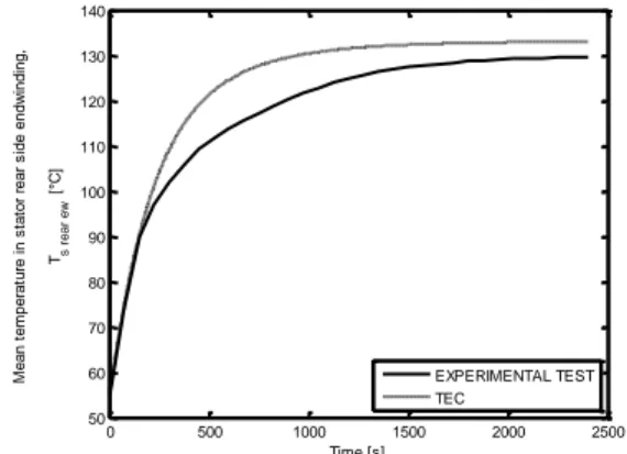
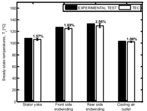
with the experimental test results. The hottest point of an open WRSM with forced cooling is its stator end-winding rear side, because of relatively high current and relatively poor cooling of the fan opposite zone comparing to the zones exposed directly to the cooling flow. A slight difference between measured and calculated steady state temperatures that does not exceed 5 % of the maximal measured value and a minor difference of the time constants could be explained by:
- the uncertainty of heat sources identification; - the uncertainty of heat transfer coefficients estimation; - unknown thermal properties of some components of the
machine, especially those of thermally anisotropic components (i.e., steel sheets and winding);
- imperfect contact between solids;
- local measurements of thermally non-uniform zones of the machine;
- the uncertainty of thermal sensors.
However, the tendency of temperature over-estimation inside the WRSM is mainly leaded by an over-estimation of the heat sources. Particularly, an over-estimation of the hottest part of the machine (rear-side end-winding) could be observed. This tendency is positive in point of view of the security requirements of the machine and its environment, which is very important in the aerospace industry.
IV. CONCLUSION
This paper is dealing with coupling of magnetic and thermal analysis of WRSM based on the equivalent circuit methods. The main principles of MEC and TEC, as well as the importance of their coupling have been introduced. A new approach called “Air-gap sliding-line technic” permitting to connect stator and rotor has been implemented for the first time on a WRSM. The results of this new 2-D nonlinear adaptive MEC are compared to 2-D FEA results. A sensibility study of proposed MEC analysis has shown that the results of MEC could be improved by increasing of the model discretization. However, it should be underlined that the design optimization process leads to a significant time cost. That’s why there has to be a compromise made between analysis accuracy and time of calculation. The results of 3-D transient TEC coupled with MEC are compared to the experimental thermal test results, which permitted to validate the principle of advection introduced in proposed analytical thermal analysis. Calculated temperatures of different parts of the machine at steady state are compared to those obtained experimentally. The mean error is less than 3 %.
Fig. 13. Mean temperature in the stator yoke.
Fig. 14. Mean temperature in the stator end-winding front side.
Fig. 15. Mean temperature in the stator end-winding rear side.
Fig. 16. Mean temperature of cooling air outlet.
0 500 1000 1500 2000 2500 50 60 70 80 90 100 110 Time [s] M e a n t e m p e ra tu re i n s ta to r y o k e , Ts y o k e [ °C ] EXPERIMENTAL TEST TEC 0 500 1000 1500 2000 2500 50 60 70 80 90 100 110 120 130 Time [s] M e a n t e m p e ra tu re i n s ta to r fr o n t s id e e n d w in d in g , Ts f ro n t e w [ °C ] EXPERIMENTAL TEST TEC 0 500 1000 1500 2000 2500 50 60 70 80 90 100 110 120 130 140 Time [s] M e a n t e m p e ra tu re i n s ta to r re a r s id e e n d w in d in g , Ts r e a r e w [ °C ] EXPERIMENTAL TEST TEC 0 500 1000 1500 2000 2500 50 60 70 80 90 100 110 Time [s] M e a n t e m p e ra tu re o f c o o lin g a ir o u tl e t, Ta ir o u tle t [ °C ] EXPERIMENTAL TEST TEC
Fig. 17. Comparison of experimental test and TEC results.
ACKNOWLEDGMENT
This work was supported by Airbus Helicopters, Marignane, France in partnership with “Université de Bourgogne Franche-Comté” (UBFC) and FEMTO-ST CNRS.
REFERENCES
[1] J. Blandino, “Overview of electric propulsion research in U.S. academia,”
39th AIAA Joint Propulsion Conference, Jul. 2003.
[2] J. Driesen, R. Belmans, K. Hameyer, “Coupled magneto-thermal simulation of thermally anisotropic electrical machines,” in Proc.
IEMDC, Seattle, Washington, USA, 9-12 May, 1999.
[3] Z. Huang, J. Fang, X. Liu, B. Han, “Loss Calculation and Thermal Analysis of Rotors Supported by Active Magnetic Bearings for High-speed Permanent Magnet Electrical Machines,” IEEE Trans. Ind. Elec., vol. 63, no. 4, pp. 2027-2035, Apr. 2016.
[4] K. Wang, Y. Le, B. Dong, B. Han, “Multi-physics design and experiment of a 315kW/20000rpm electrical machine with a magnetically suspended flexible rotor”, in Proc. ICEMS, Chiba, Japan, Nov. 13-16, 2016.
[5] C. Kan, G. Chu, J. Zhang, “Design and electromagnetic-thermal analysis of a 64kW doubly-sine wound-rotor brushless doubly-fed generator,” in
Proc. ICEMS, Hangzhou, China, Oct. 22-25, 2014.
[6] B. Dong, “High-speed permanent magnet motor with magnetic bearings: multi-physics analysis, cooling design and experiment,” in Proc. ICEMS, Chiba, Japan, Nov. 13-16, 2016.
[7] I. Petrov, M. Polikarpova, J. Pyrhönen, “Rotor surface ferrite magnet synchronous machine for generator use in a hybrid application – electro-magnetic and thermal analysis,” in Proc. IECON, Vienna, Austria, Nov. 10-13, 2013.
[8] S. Mezani, N. Takobet, B. Laporte, “A combined electromagnetic and thermal analysis of induction motors,” IEEE Trans. Magn., vol. 41, no. 5, pp. 1572-1575, May 2005.
[9] L. Alberti, N. Bianchi, “A coupled thermal-electromagnetic analysis for a rapid and accurate prediction of IM performance,” IEEE Trans. Ind. Elec., Oct. 2008. [10] Z.W. Vilar, D. Patterson, R.A. Dougal, “Thermal analysis of a single
sided axial flux permanent magnet motor,” in Proc. IECON, Raleigh, NC, USA, Nov. 06-10, 2005.
[11] M.I. Lamghari-Jamal, J. Fouladgar, E-H. Zaim, D. Trichet, “A magneto-thermal study of a high-speed synchronous reluctance machine,” IEEE
Trans. Magn., vol. 42, no. 4, pp. 1271-1274, Apr. 2006.
[12] P-W. Han, “Thermal analysis of high speed induction motor by using lumped-circuit parameters,” J Electr Eng Technol, vol. 10, pp. 1921-718, 2015, http://dx.doi.org/10.5370/JEET.2015.10.5.1921.
[13] A. Daanoune, R. Lateb, J. Da Silva, “Semi analytical model for eddy current losses calculation in high speed permanent magnet synchronous machines,” in
Proc. ICEMS, Chiba, Japan, Nov. 13-16, 2016.
[14] H.K. Yeo, H.J. Park, J.M. Seo, S.Y. Jung, J.S. Ro, H.K. Jung, “Coupled electromagnetic-thermal analysis of a surface-mounted permanent-magnet motor with overhang structure,” in Proc. CEFC, Miami, FL, USA, Nov. 13-16, 2016.
[15] J. Legranger, G. Friedrich, S. Vivier, J.C. Mipo, “Design of a brushless rotor supply for a wound rotor synchronous machine for integrated starter generator,” in Proc. VPPC, Arlington, TX, USA, Sep. 09-12, 2007. [16] G. Bertotti, “General properties of power losses in soft ferromagnetic
materials,” IEEE Trans. Magn., vol. 24, no. 1, pp. 621-630, Jan. 1988.
[17] O. Messal, F. Dubas, R. Benlamine, A. Kedous-Lebouc, C. Chillet, C. Espanet, “Iron losses in electromagnetic devices: nonlinear adaptive MEC & dynamic hysteresis model,” Preprints (MDPI: Energies), 2017. [18] H.C. Roters, “Electromagnetic Devices,” New York: Wiley & Sons, 1941. [19] V. Ostović, “Dynamics of Saturated Electric Machines,” Springer-Verlag
New York Inc., (DOl: 10.1007/978-1-4613-8933-0), 1989.
[20] C.B. Rasmussen, E. Ritchie, “Magnetic equivalent circuit method for designing permanent magnet motors,” in Proc. ICEM, Vigo, Spain, Sep. 10-12, 1996.
[21] J. Perho, “Reluctance network for analyzing induction machines”, Acta Polytech.
Scandinavica, Electr. Eng. Series, vol. 110, pp. 01-147, Dec. 2002.
[22] F. Dubas, R. Benlamine, S-A. Randi, D. Lhotellier, C. Espanet, “2-D or quasi 3-D nonlinear adaptive magnetic equivalent circuit, Part I: Generalized modeling with air-gap sliding-line technic,” Applied Energy, under review. [23] R. Benlamine, F. Dubas, S-A. Randi, D. Lhotellier, C. Espanet, “2-D or
Quasi 3-D nonlinear adaptive magnetic equivalent circuit, Part II: Application to axial-flux interior permanent-magnet synchronous machines,” Applied Energy, under review.
[24] R. Benlamine, F. Dubas, F., S-A. Randi, D. Lhotellier, C. Espanet, “Modeling of an axial-flux interior PMs machine for an automotive application using magnetic equivalent circuit,” in Proc. ICEMS, Pattaya, Thailand, 25-28 Oct., 2015.
[25] R. Benlamine, Y. Benmassaoud, F. Dubas, C. Espanet, “Nonlinear adaptive magnetic equivalent circuit of a radial-flux interior permanent-magnet machine using air-gap sliding-line technic,” in Proc. VPPC, Belfort, France, Dec. 11-14, 2017, accepted.
[26] R. Benlamine, T. Hamiti, F. Vangraefschèpe, F. Dubas, D. Lhotellier, “Modeling of a coaxial magnetic gear equipped with surface mounted PMs using nonlinear adaptive magnetic equivalent circuits,” in Proc.
ICEM, Lausanne, Switzerland, Sep. 04-07, 2016.
[27] M.N. Özişik, “Heat conduction,” John Wiley & Sons Inc., 1993 (ISBN 0-471-53256-8)
[28] D. Roye, R. Perret, “Définitions des règles de modélisation thermique des machines électriques tournantes,” EDP Sciences, 1985.
[29] Sh. Utegenova, R. Glises, Ph. Desevaux, F. Dubas, D. Mariotto, B. Truffart, “Comparison of 3D thermal equivalent circuit architectures of asynchronous machines,” in Proc. ICEM, Lausanne, Switzerland, 4-7 Sept. 4-7, 2016. [30] R. Glises, “Machine électriques tournantes - simulation du comportement
thermique,” Techniques de l’Ingénieur, D 3 760, 1998.
[31] A. Bousbaine, “An investigation into the thermal modelling of induction motors,” Ph.D. dissertation, Dept. of Electronics and Electrical Engineering, University of Sheffield, 1993.
[32] J.K. Coldwate, J.M. Beck, D. Pal, M. Lusie, “Stator cooling channel tolerant to localized blochage,” U.S. Patent 2014 0117798 A1, May 2014.
[33] D.A. Staton, A. Cavagnino, “Convection heat transfer and flow calculations suitable for electric machines thermal models,” IEEE Trans.
Ind. Elec., vol. 55, no. 10, pp. 3509-3516, Oct. 2008.
[34] A. Nollau, D. Gerling, “A new cooling approach for traction motors in hybrid drives,” in Proc. IEMDC, Chicago, IL, USA, May 12-15, 2013. [35] J. Pyrhönen, T. Jokinen, V. Hrabovcová, “Design of rotating electrical
machines,” John Wiley & Sons, Ltd, 2008 (ISBN: 978-0-470-69516-6) [36] J.R. Hendershot, T.J.E. Miller, “Design of brushless permanent-magnet
machines,” Motor Design Books, 2010 (ISBN: 978-0-984-06870-8). [37] G.W. Milton, “Bounds on the transport and optical properties of a
two-component composite material,” Journal of Applied Physics, 1981. [38] M.L. Idoughi, “Extraction de modèles thermiques simplifiés des machines
électriques à partir d’un calcul du champ de températures,” Ph.D. dissertation, Université Paris-Sud, 2011.
[39] Y. Bertin, “Analyse des transferts de chaleur dans un moteur électrique asynchrone - développement d’un environnement C.A.O. et modélisations thermo aérauliques,” Ph.D. dissertation, Université de Poitiers ENSMA, 1987. [40] A. Ben Nachouane, “Modélisation numérique des phénomènes aérothermiques
dans les machines électriques en vue d’optimisation de leur conception: application aux machines électriques des véhicules hybrides et électriques,” Ph.D. dissertation, Université de Technologie de Compiègne, 2017.
[41] R. Siegel, R.W. Graham, “Effect of fin passage on optimization of cylinder head cooling fins,” NASA Technical Paper, 1977.
[42] A. Giret, “Transfères thermiques convectifs dans le cadre de machines tournantes,” Ph.D. dissertation, Université de Poitiers, 2006.
[43] General Electric, “Heat transfer and fluid data book,” Genium Publishing
Corporation, 1985 (ISBN : 0-931690-02-1).
[44] M. Jääskeläinen, “Determination of coefficients of thermal convection in a high-speed electrical machine,” M.S. thesis, Dept. of Electrical Engineering, Helsinki University of Technology, 2009.
0 20 40 60 80 100 120 140 160
Stator yoke Front side endwinding Rear side endwinding Cooling air outlet S te a d y -s ta te t e m p e ra tu re s , Ti [ °C ] 1.57% 1.69% 2.56% 1.06% EXPERIMENTAL TEST TEC
[45] S. Poncet, S. Haddadi, S. Viazzo, “Numerical modeling of fuid fow and heat transfer in a narrow Taylor-Couette-Poiseuille system,” Int. J. of Heat and
Fluid Flow, Elsevier, 2010.
[46] G.E. Luke, “The cooling of electric machines,” IEEE Trans. of the Amer.
Inst. of Elect. Eng., 1923.
[47] E. Schubert, “Heat transfer coefficients at end winding and bearing covers of enclosed asynchronous machines,” Elektrie, 1968.
[48] A. Boglietti, A. Cavagnino, D.A. Staton, M. Popescu, “Impact of different end region cooling arrangements on endwinding heat transfer coefficients in electric motors,” in Proc. IECON, Porto, Portugal, Nov. 03-05, 2009. [49] K.R. Anderson, J. Lin, C. McNamara, V. Magri, “CFD study of forced air
cooling and windage losses in a high speed electric motor,” J. of Electron.
Cooling and Thermal Control, 2015.
[50] L.F.G. Geers, “Multiple impinging jet arrays: an experimental study on flow and heat transfer,” Ph.D. dissertation, Technical University of Delft, 2004. [51] I.E. Idel’chik, “Handbook of hydraulic resistance: coefficients of local
resistance and of friction,” Gos. Energ. Izd. Moskva-Leningrad, 1960. [52] T. Astarita, G. Gardone, “Convective heat transfer on a rotating disk with a
centred impinging round jet,” Int. J. of Heat and Mass Transfer, 2008. [53] A. Bornschlegel, “Optimisation aérothermique d’un alternateur `a pôles
saillants pour la production d’énergie électrique décentralisée,” Ph.D. dissertation, Université de Valenciennes, 2012.
[54] J.-F. Trigeol, Y. Bertin, P. Lagonotte, “Thermal modelling of an induction machine through the association of two numerical approaches,” IEEE Trans.
Energy Conv., vol. 21, no. 2, pp. 314-323, June 2006.
[55] H.O. Jimenez, “AC resistance evaluation of foil, round and litz conductors in magnetic components,” M.S. thesis, Chalmers University of Technology, 2013.
Shinara Utegenova was born in Kazakhstan.
She received the B.Sc. in Engineering Science from the Peoples Friendship University of Russia in Moscow in 2012. In 2013, she received the M.Sc. degree in Engineering Science from the University of Pierre and Marie Curie in Paris. In September 2014, she started her Ph.D. research at FEMTO-ST Institute (UMR CNRS 6174) / ENERGY Department, University of Bourgogne Franche-Comte (UBFC), in collaboration with Airbus Helicopters. Her research interests include magnetic and thermal modelling, loss analysis, and design of electric machines particularly for aerospace hybridization.
Frédéric Dubas was born in Vesoul, France,
in 1978. He received the M.Sc. degree and the Ph.D. degree from the “Université de Franche-Comté” (UFC), Vesoul and Belfort (France), with a focus on the design and the optimization of high-speed surface-mounted permanent-magnet (PM) synchronous motor for the drive of a fuel cell air-compressor, in 2002 and 2006 respectively.
He is currently an Associate Professor with the Département ENERGIE, FEMTO-ST Institute affiliated to the CNRS. He is involved in industrial applications for the modelling, design and optimization of electrical systems.
He has published over 50 refereed publications and he holds a patent for the manufacturing of flux-focusing axial-flux PM machines. Dr. Dubas received the Prize Paper Awards in the IEEE Conference Vehicle Power and Propulsion (VPPC) in 2005, as well as the Prize Presentation Awards in the 19th International Conference on Electrical Machines and Systems (ICEMS) in 2017.
Michel Jamot is power electronics expert at Airbus Helicopters,
Marignane, France. He has more than 20 years’ experience in the development of power converters and machine drives for navy and aerospace applications.
Since 2011 he has been working especially on reversible DC-DC conversion, and new technology of starter-generator for new and next generations of helicopters.
Raynal Glises is an Associate Professor at
the University of Bourgogne Franche-Comté. He received the Ph.D. degree in Engineering Sciences from the University of Franche-Comté in 1994. He is currently the head of the THERMIE Team of the ENERGY Department, FEMTO-ST Institute. His research interests are focused on the field of the thermal management of electric motors, including the thermal modelling by nodal method.
Bertrand Truffart is Dr-Engineer of
Polytech’Nantes (1991) and the University of Nantes (1996). His Ph.D. thesis was focused on Inverse Heat Transfer problems. He is currently working at Airbus Helicopters at Marignane as thermal engineer, more precisely in the frame of Method and Tools, Research and Development activities.
Damien Mariotto was born in Aix-en-Provence, France, in 1982. He
was graduated in 2007 from two Engineering schools: SUPELEC, Paris, France, and Ecole Nationale Supérieure d’Arts et Metiers, Paris, Aix-en-Provence. He is currently working at AIRBUS HELICOPTERS at Marignane as an electrical systems Engineer and more precisely in the power machine field within Research and Development activities frame.
Patrick Lagonotte was born in Paris, France
in 1959. He obtained his Electrical Engineering degree from Ecole Normale Supérieure de Cachan in 1984 and his Doctorate from Institut National Polytechnique de Grenoble in 1987. After working at EDF's R&D Department and at Grenoble Electrotechnical Laboratory, he is now a Professor and teaches Electrical Power at the University of Poitiers. His main research topics are system modeling, models reduction, partial derivative equations such as diffusion and propagation, modelling of infinite order or no integer systems.
Philippe Désévaux is 53 years old. He is
currently a Full Professor at the University of Bourgogne Franche-Comté (France). He obtained his PhD in 1994 and carries out his research activities within the Energy Department of the FEMTO-ST Institute in the fields of thermal engineering, heat transfer, experimental and numerical fluid dynamics. He is the author of about 70 scientific publications in international journals and congresses.