OATAO is an open access repository that collects the work of Toulouse
researchers and makes it freely available over the web where possible
Any correspondence concerning this service should be sent
to the repository administrator:
[email protected]
This is an author’s version published in:
http://oatao.univ-toulouse.fr/27603
To cite this version:
Vidal, Elia and Guillem-Marti, Jordi and Ginebra, Maria-Pau and Combes,
Christèle
and Rupérez, Elisa and Rodriguez, Daniel Multifunctional
homogeneous calcium phosphate coatings: Toward antibacterial and cell
adhesive titanium scaffolds. (2021) Surface and Coatings Technology, 405.
126557. ISSN 0257-8972
Multifunctional homogeneous calcium phosphate coatings: Toward
antibacterial and cell adhesive titanium scaffolds
Elia Vidal a
,b'
Jordi Guillem-Marti a
. ,b'
Ma1ia-Pau Ginebra a
,b,c'
Christèle Combes
d'
Elisa Rupérez
a
,
h,
Daniel Rod1iguez
a
,
b
,
*
, Biomaterials, Biomechanics and Tissue Engineoing Group, Department of Marerials Science and Enginllring, Universitat Politècnica de Catalunya (UPC), Av. Eduard Maristany 10, 08019 BcuœlonD, Spain
b Barcelona &.earch Center in Multiscale Science and Enginllring, Universitnt Poliœcnica de Catalunya, Av. Eduard Maristany 10, 08019 BarcelonD, Spain
'lnstitute for Bioengineering of Catalonia (TBEC), Barcelona /nstiture of Science and Technology (BIS1), Baldiri I Reixac 10, 08028 Barcelona, Spain
d CIRIMAT, Université de Toolouse, CNRS, Toolouse /NP -ENSIACET, 4 allée Emile Monso, CS 44362, 31030 Toulouse cedex 4, France
ARTICLE INFO Titaniwn scaffolds Calciwn phosphate coating Chlorhexidine dig)uconate Antibacterial
Biocompatibility
On-ep pulse electrodeposition
1. Introduction
AB STRA CT
Implants for onhopedic applications need to be biocompatible and bioactive, with mechanical properties similar to chose of surrounding narural bone. Given this scenario titaniun1 (Ti) scaffolds obtained by Direct Ink Writing technique offer the opportunicy to manufacture customized structures with controlled porosicy and mechanical properties. Considering chat 3D Ti scaffolds have a significant surface area, it is necessary to develop strategies against the initial bacterial adhesion in order to prevent infection in the early stages of the in1plantation, while promoting cell adhesion to the scaffold. The challenge is not only achieving a balance between antibacterial activity and osseointegration, it is also to develop a homogeneous coating on the inner and outer surface of the scaffold.
The purpose of this work was the development of a single-step electrodeposition process in order to unifomtly cover Ti scaffolds with a layer of calcium phosphate (CaP) loaded with chlorhexidine digluconate (CHX). Scaffold characterization was assessed by scarming electron microscopy, Energy dispersive X-ray spectroscopy, X-ray
diffraction, micro-Ranlan microscopy and compressive strength tests. Results determined chat the surface of scaffolds was covered by plate-like and whisker-like calciun1 phosphate crystals, which main phases were octacalcium phosphate and brushite. Biological tests showed chat the as-coated scaffolds reduced bacteria
adhesion (73 ± 3% for Scaphylococcus aureus and 70 ± 2% for Escherichia coli). ln vicro cell scudies and confocal analysis revealed the adhesion and spreading of osteoblast-like SaOS-2 on coated surfaces. Therefore, the pro posed scrategy can be a potential candidate in bone replacing surgeries.
The overall rise in life expectancy has resulted in an increase in the use of medical devices such as orthopedic prostheses. These implants require an excellent osseointegration and stiffness sintilar to that of natural bone [1]. Titanium (Ti) has been widely used as a biomate1ial due to its biocompatibility and good mechanical prope1ties [2]. Exces sive stiffness and Jack of osseointegration, however, can be a problem for Ti-based implants [3].
elastic modulus between metallic implant and bone [ 4]. Additive manufactming technologies based on building layer-by-layer stt·uctures with contt·olled geomett·ies, such as open-cell structures, have become more accurate and more accessible [5-7]. These fabrication processes have already allowed the production of custontized orthopedic implants such as acetabular cups or inte1vertebral dises [8].
Among the different 3D printing existing techniques, direct ink
writing (DIW) fabrication process using Ti pseudoplastic inks is
considered a promising methodology to build 3D Ti scaffolds at room temperature, followed by an appropriate thermal n·eatment. In a pre
vious study, the preparation of such scaffolds and the optimization of the
The use of open-cell titanium structures has been considered a prontising candidate in orthopedic in1plants to reduce the ntismatch in
• Corresponding author ac: Biomaterials, Biomechanics and Tissue Engineering Group, Departrnent ofMaterials Science and Engineering, Universitat Politècnica de Catalunya (UPC), Av. Eduard Maristany 10, 08019 Barcelona, Spain.
E-mail address: [email protected] (D. Rodriguez). https:/ /doi.org/10.1 Ol 6/j.surfcoat.2020.126557
osteogenic cells (SaOS-2) and the antibacterial activity was evaluated against both Gram-positive Staphylococcus aureus (S. aureus) and Gram- negative Escherichia coli (E. coli) models.
2. Materials and methods
2.1. Scaffolds fabrication by direct ink writing
Ti ink was prepared by mixing irregular Ti powder (~325 mesh, 99.5% purity, Alfa Aesar, USA) with Pluronic® F127 hydrogel 30% w/v. The development of the Ti ink and the posterior thermal treatment was
previously optimized [9]. Briefly, 69% w/w of Ti powder was mixed
with 31% w/w of Pluronic® hydrogel in a centrifuge (Speedmixer, DAC 150.1 FVZ-K) for 5 min at 3500 rpm. The resulting Ti ink was introduced
in a 3 cm3 syringe and placed in the 3D printing machine (Pastecaster,
BCN3D Technologies, Spain). G-codes of a 0–90◦pattern were loaded to
the 3D printing machine in order to obtain cylindrical samples of 13 mm diameter and 5 mm height. For mechanical properties tests, samples of 13 mm diameter and 18 mm height were prepared with the same pattern. Once printed, samples were introduced in an oven for 12 h at
275 ◦C to eliminate the binder and finally sintered in a tubular furnace
(Carbolite, UK) at 1350 ◦C under vacuum (10−5 mbar) for 2 h.
2.2. Coating of the scaffolds with CaP by pulsed reverse electrodeposition
Coating of 3D printed scaffolds was performed by pulsed reverse electrodeposition. Before the electrodeposition process, scaffolds were
soaked in a 5 M NaOH solution for 24 h at 60 ◦C to generate a thin
titanate layer and finally rinsed with ultrapure water and dried in a desiccator. Calcium phosphate coatings were obtained by applying a current to the treated Ti scaffolds in an electrolyte prepared by mixing
0.042 M of Ca(NO3)2⋅4H2O and 0.025 M of NH4H2PO4 solutions with a
Ca/P molar ratio of 1.67, at pH 4.2. All reagents were analytical grade (Sigma-Aldrich, USA). The pulsed reverse electrochemical deposition was carried out in an individual cell using a three-electrode configura-tion in which a platinum electrode was used as an anode, a saturated calomel electrode (SCE) as reference electrode and the Ti scaffolds as cathode. Electrodeposition was conducted by using a potentiostat (PARSTAT 2273, Princeton Applied Research, Oak Ridge, TN, USA) and
pulsing the current for 30 min at 40 ◦C [16]. A current density of 10 mA/
cm2 was first applied for 1 s, then current was switched off for 1.6 s (time
off). Subsequently, current was regulated to 20 mA/cm2 for 0.2 s and
raised again to 0 mA/cm2 for 0.2 s.
Samples loaded with chlorhexidine digluconate 20% w/v (Sigma- Aldrich, USA) were prepared by adding 0.75, 1.5 and 3 mM CHX to the electrolyte solution at concentrations, hereafter named CaP+0.75mMCHX, CaP+1.5mMCHX and CaP+3mMCHX, respectively. Different concentrations of CHX were tested in order to study the min-imum concentration required to have an antibacterial response. After electrodeposition process, Ti scaffolds were rinsed with distilled water and dried in a desiccator.
2.3. Scaffolds characterization
Scaffolds architecture was observed by micro-computed tomography (micro-CT, SkyScan 1272, Bruker, Belgium) at a source voltage of 90 kV
and current of 111 μA, using an image pixel size of 15 μm. Subsequently
3D reconstruction was carried out using Nrecon software (Bruker). Surface morphology of both coated and uncoated scaffolds were analyzed by scanning electron microscopy (SEM, Zeiss Neon 40, Carl Zeiss, Germany), using a working distance of 12 mm and an acceleration voltage of 5 kV. Furthermore, the coating thickness was analyzed by studying cross-sectional SEM images of three samples that were previ-ously immersed in liquid nitrogen and fractured. Energy-dispersive X- ray spectroscopy (EDX) analyses of cryofractured samples were acquired with a FE-SEM JEOL JSM-7001F (Jeol, Tokyo, Japan) complemented
fabrication parameters were discussed [9]. The main advantage of this
technique compared to powder-bed processes rests on the fact that no depowering process is needed. In consequence, post-production time, material waste, and the risk of the presence of remaining particles associated to inflammatory responses are reduced.
Another factor to consider is that Ti is an inert material. Therefore, it is ineffective for defeating infections nor promoting bone cell adhesion. Surface functionalization is one of the strategies to change surface properties such as surface bioactivity and implant-related infections.
To this end, different coating strategies have been proposed to overcome these drawbacks. One approach is to mimic the inorganic part of the bone by covering the Ti surface with a calcium phosphate (CaP)
coating [10]. An existing strategy for coating Ti scaffolds is based on
reverse pulsed electrodeposition, which presents several advantages compared to other coating methodologies such as plasma spraying, sol-
gel or biomimetic processes [11–17]. Since the process takes place at
low temperature, a higher control of the thickness and chemical composition of the coating is achieved while maintaining a high
effi-ciency [18].
Besides, in comparison with conventional electrodeposition, the production of hydrogen bubbles deleterious to the coating formation is reduced and the ion depletion in the boundary layer close to the treated
surface is avoided because of the pulses of reverse polarities [19]. It
should be emphasized that, while some line-of-sight technologies such as plasma spray coating can only coat simple geometries, pulsed elec-trodeposition has not such limitations and can coat 3D structures,
including micropores or recesses [20]. Moreover, compared with other
non-line-of-sight techniques, e.g., biomimetic coating, that requires soaking the scaffold for 3 days, electrodeposition is much faster, wholly
coating a surface after only 30 min [16].
Another important aspect related to implant osseointegration is the prevention of implant-related infections, which may produce local inflammation and eventually implant rejection. Among the different strategies, the local release of an antibacterial agent is the best alter-native to systemic administration. In this regard, a CaP coating can act as a carrier for drug delivery in order to improve not only metallic implant limitations related to bioactivity but also antibacterial response by
reducing bacterial colonization [21]. Several authors have reported the
benefits of the adsorption of antibiotics on biomaterials surfaces. How-ever, the use of antibiotics has to be rationalized in order to prevent
microbial resistance [22,23]. For that reason, chlorhexidine digluconate
(CHX) is an antiseptic which has been used as a model of antibacterial
agent [24]. It is active against an array of microorganisms, including
Gram-positive and Gram-negative bacteria, and has a low risk of asso-ciated drug resistance. CHX antibacterial activity is due to the interac-tion of the cainterac-tionic group of the molecule with negatively charged bacteria cell wall. This effect is concentration-dependent: bacteriostatic
at low concentrations and bactericidal at high concentrations [25].
Furthermore, it has been shown that CaP and CHX can be co-deposited during the electrodeposition, unlike other two-steps strategies that
consist on immersing CaP layer in a CHX-loaded solution [16,26].
However, designing a one-step homogeneous coating on a scaffold sur-face with antibacterial response that simultaneously enhances cells adhesion remains a challenge.
In the present study a Ti scaffold, manufactured with a novel DIW technique, was functionalized with a multifunctional calcium phosphate coating with the aim to promote implant osseointegration by reducing bacterial adhesion and stimulating bone cell adhesion. The main novelty of this work was to obtain a uniform CaP coating loaded with CHX by single-step pulse reverse electrodeposition in a 3D structure. Thus, the main challenge related with the electrodeposition process was to ach-ieve enough throughput potential to permit the layer formation inside the scaffold architecture and not only on its surface. Moreover, the concentration of CHX in the coating must be adjusted in order to combine the bioactivity of CaP with antimicrobial effect of CHX. The biological response of the coating was tested in vitro with sarcoma
Diluted bacterial suspensions were adjusted to an absorbance of 0.02
±0.01 at 600 nm using a photometer (Laxco MicroSpek™ DSM, USA)
corresponding to a bacterial concentration of 107 colony-forming units
(CFU)/mL. Then, samples were immersed in 2 mL of inoculated media
using a 48 double-well culture well-plate previously prepared [28]. The
antibacterial activity was monitored for 16 h by measuring absorbance at 600 nm with a multimode microplate reader (Synergy™ HTX Multi-mode reader, USA). Negative and positive culture controls were pre-pared with medium without bacteria and bacterial suspension, respectively. Ti scaffolds without coating were used as control. More-over, for future applications of the implant in vivo, it is indispensable to check their stability after sterilization. In this regard, CHX-loaded scaf-folds were sterilized with gamma radiation (25 kGy, Aragogamma S.L., Spain) and challenged with S. aureus bacterial strain in order to detect any effect of the sterilization technique on the antibacterial response.
2.4.2. Inhibition of bacterial adhesion
Coated scaffolds were immersed in 500 μL of bacteria suspension
previously adjusted to an absorbance of 0.2 ± 0.1 (108 CFU/mL) and
incubated for 2 h at 37 ◦C. Then, specimens were rinsed with PBS and
incubated in Alamar Blue solution (10% v/v in medium) (AB,
Thermo-Fisher, Belgium) for 1 h at 37% in dark [29]. After this time, 100 μL
supernatant for each condition were introduced in a 96 well-plate in
order to measure the absorbance by using a microplate reader at λ1
570 nm and λ2 600 nm. The following formula was used to calculate
the percentage difference of reduction:
[((εox)λ2A0λ1 (εox)λ1A0λ2)test/((εox)λ2Aλ1 (εox)λ1Aλ2)untreated ] × 100 (1)
In Eq. (1), εox is the molar extinction coefficient of Alamar Blue
oxidized form ((εox) λ1 80.586 and (εox) λ2 117.216), A0 and A
represent the absorbance of negative control well (media + AB without bacteria) and absorbance of positive control well, respectively. Untreated corresponds to untreated positive growth control and test, to target samples.
Finally, samples were fixed with 2.5% glutaraldehyde in PBS for 1 h
at 4 ◦C. Afterwards, samples were dehydrated by immersing them
suc-cessively in ethanol series (50%, 70%, 96% and 100%) in order to be observed by SEM at 5 kV.
2.5. Cell biocompatibility 2.5.1. Cell adhesion
Cellular tests were performed with human osteoblast-like SaOS-2 cells (ATCC, USA) cultured in McCoy’s 5A medium (Sigma-Aldrich) supplemented with 10% v/v fetal bovine serum (FBS), 50 U/mL
peni-cillin, 50 μg/mL streptomycin, 20 mM HEPES and 2 mM L-glutamine, all
from Invitrogen.
Cell adhesion on Ti scaffold surfaces loaded with CHX was conducted
at a density of 8⋅104 cells/well, on quintuplicate specimens and
incu-bated for 6 h at 37 ◦C, 5% CO
2 in a humidified environment. After
in-cubation, cells were lyzed with mammalian Protein Extraction Reagent (m-PER, Pierce, Rockford, IL, USA). The number of attached cells was quantified by analyzing the lactate dehydrogenase (LDH) activity using the cytotoxicity detection kit LDH (Roche Applied Science, Germany). The absorbance values were measured at 492 nm with a microplate reader (Synergy™ HTX Multimode reader, USA) and then, the number of attached cells was determined using a calibration curve. Uncoated Ti scaffolds were used as controls.
Additionally, one specimen of each condition was prepared as described above, for studying cell spreading and morphology by SEM at 2 kV.
2.5.2. Fluorescence staining
A fluorescence staining was performed in order to study cell morphology and distribution on Ti and CHX-loaded Ti scaffolds surfaces. After 6 h incubation, cells were fixed with paraformaldehyde 4% w/v in PBS, permeabilized for 20 min in Triton X-100 0.1% w/v in PBS in order to allow the molecules diffusion into the cell, and finally a blocking step was conducted by immersing the specimens in bovine serum albumin (BSA 1% w/v in PBS) for 30 min. Alexa Fluor 546 Phalloidin (1:300 in
triton 0.05%) was used to stain actin filaments for 1 h and 4′
,6-dia-midino-2-fenilindol (DAPI 1:1000 in PBS-glycine 20 mM) for 2 min to stain the nuclei, both in the dark. Specimens were washed with PBS- glycine solution three times for 5 min, between each step. Specimens were mounted with Mowiol 4-88 (Sigma-Aldrich) and visualized using a Zeiss LSM 800 confocal microscope (Carl Zeiss, Jena, Germany). A laser emission at 640 nm was used to obtain a reflection image of the scaffold.
2.6. In vitro drug release
CHX release studies were carried out by immersing scaffolds loaded with CHX in 1 mL of tris(hydroxymethyl)methylamine buffer solution (TRIS, VWR International Ltd., UK) at physiological pH, for 14 days and
37 ◦C, under SINK conditions (sufficient media is present in relation to
the drug to be dissolved). At each time point, all solution was removed and replaced by new medium. For the quantification of the CHX released, absorbance was measured with a UV-spectrophotometer (λ 254 nm; Shimadzu model 3600, Tokyo, Japan). Triplicates of each condition were used. Moreover, in order to calculate the percentage of released CHX at each time point, the real amount of loaded CHX was with an energy dispersive X-ray spectrometer using a working distance
of 10 mm and an acceleration voltage of 20 kV.
Calcium phosphate crystalline phases of the coating were identified
by X-ray diffraction (XRD) using a monochromatic Cu Kα radiation (D8
Advance Instrument, Bruker, Germany) at a scan rate of 0.25◦/s, in the
2θ range of 4–45◦ with rotation.
Moreover, coated scaffolds were analyzed using Micro-Raman spectroscopy combined with a confocal microscope (LabRam HR 800 Confocal Raman, Horiba Jobin Yvon, UK) that permitted to focus on a specific area, using a 532 nm laser, a 600 g/mm grating and a 100× magnification objective. Acquisition of single spectrum from points of interest was performed by taking 20 accumulations of three-second integration periods. Spectra were plotted from an average of three scans of 60 s each.
Surface roughness of Ti scaffolds and CaP-coated scaffolds was observed by using a white light interferometer Wyko NT9300 Optical Profiler (Veeco Instruments, Plainview, NY, USA) in vertical scanning interferometry mode (VSI). Three measurements of the average surface
roughness (Ra) were obtained at three different zones of the scaffold,
using a 10× objective lens and a scanning area of 316 × 237 μm.
Roughness data was analyzed with Wyko Vision 4.10 software (Veeco Instruments).
The response of the scaffolds to a compressive load, with and without coating, was also evaluated. Five scaffolds (n 5) of 18 × 13 mm were tested for each condition using a compression testing machine (Microtest machine EM1/20/FR, Microtest, Spain) at a speed of 2.5 mm/
min, in accordance with ISO 13314:2011 [27]. The elastic modulus and
ultimate strength were determined from the stress-strain curves as defined in the ISO standard.
2.4. Antibacterial properties 2.4.1. Bacterial growth curve
The antibacterial activity was studied on Ti scaffolds loaded with CHX at 0.75, 1.5 and 3 mM. All antibacterial assays were performed against Gram-positive S. aureus (CCUG 15915, Culture Collection Uni-versity of Goteborg, Sweden) and Gram-negative E. coli (CECT 101, Colecci´on Espanola de Cultivos Tipo, Spain) bacteria, both grown in brain-heart infusion (BHI, Scharlab, Spain).
obtained by adding released and unreleased values of CHX. To this end, unreleased CHX was quantified by immersing a sample from the final
time point in 1 mL of HNO3 0.1 M and subsequently determining the
amount of CHX that remains in the coating using the corresponding calibration curve.
CHX release profile was studied by using different mathematical models (Korsmeyer-Peppas model and Kopcha).
2.7. Statistical analysis
All data presented in this study are given as mean value ± standard deviation. At least triplicate samples (n 3) were used for statistical analysis, except for compression test study and cell adhesion assay where five samples were analyzed. A non-parametric Kruskal-Wallis test followed by Mann-Whitney test with Bonferroni correction was used to determine the statistically significant differences (p < 0.05) between group means.
3. Results and discussion
3.1. Scaffolds characterization
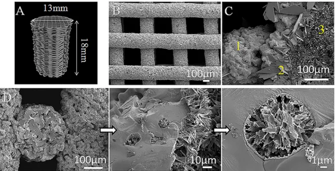
Micro-CT reconstruction of the obtained scaffolds, as well as SEM
micrographs are presented in Fig. 1. The surface of scaffolds without
coating showed the presence of neck formation between particles pro-duced during the sintering. Interestingly, SEM images of coated scaffolds revealed the presence of a homogeneous CaP coating which also covers the internal architecture and even the open pores of the scaffold (Fig. 1D). Cross-section measurements resulted in a coating thickness of
10.1 ± 0.6 μm. Coating homogeneity was probably achieved by working
with pulsed reverse current during the electrodeposition process, which reduces hydrogen gas generation at the cathode surface and enhances the ion penetration in the 3D scaffold. It is important to highlight that the coated area inside the scaffold will be protected against shear stress during implant insertion as it will not be in contact with the surrounding tissues.
Analyzing in detail the surface morphology, three different crystal
morphologies are observed: a region with large platelet-like crystals of
around 30 μm in length, another with platelet-like crystals of 15 μm and
an area composed of needle-like crystals of approximately 5 μm in length
(Fig. 1C). Roughness of the surface may be affected by this grain size of the CaP crystal structure. However, although coated scaffolds showed a
higher roughness (Ra 5.6 ± 0.7 μm), the difference with non-coated
surfaces is not significant (Ra 5.3 ± 0.3 μm) probably because the
original 3D scaffold roughness is quantitatively higher than the increased roughness due to the coating.
An EDX mapping of a cryofractured Ti scaffold (Fig. 2A), showed
mostly the presence of titanium on both the external surface and the freshly created fractured surface, with only a minor presence of C in the surface on the strut, as reported in a previous characterization of these type of scaffolds [9]. In contrast, the EDX mapping of a cryofractured
coated scaffold (Fig. 2B) reported a homogenous coating of Ca, P and O
only on the external surface of the strut. Besides, since no Ti was detected on the surface of the strut, but only on the cryofracture, the coating must be some micrometres thick, corroborating the previously commented SEM measurements. A detailed observation of the coated scaffold revealed zones with the presence of large crystals, as those seen
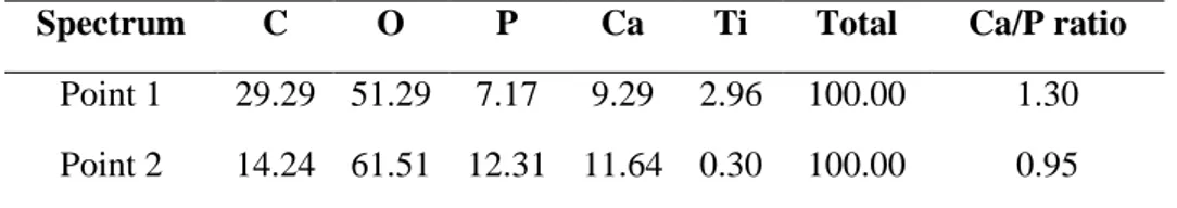
in point 2 of Fig. 1C. The EDX mapping of one of these areas (Fig. 2C)
clearly distinguished two regions with respect to the phosphorus pres-ence (and for extension to the Ca/P ratio), one for the large crystal and the rest for the area with smaller crystals. In order to quantify this effect, Ca/P ratios were calculated from EDX spot measurements carried out on
both the large and the small crystals (points 1 and 2 in Fig. 2C). The Ca/P
ratios calculated from the EDX spectra were Ca/P 1.30 for point 1 and
Ca/P 0.95 for point 2, respectively (Supplementary information,
Fig. S1 and Table S1). Both ratios are close to those expected for an
octacalcium phosphate (Ca/P 1.33) and brushite (Ca/P 1.0) [47].
Considering the semi-quantitative nature of the EDX ratio estimations, however, other techniques are required to confirm the phases present in the coating.
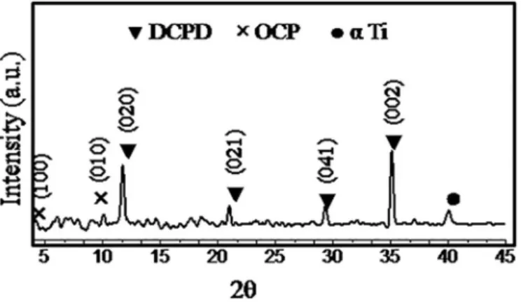
To further confirm the crystallography of the observed structures,
XRD data of a coated scaffold was studied (Fig. 3). Results revealed the
presence of sharp peaks assigned to brushite phase (DCPD,
CaH-PO4⋅2H2O, according to JCPDS no. 72-0713 brushite standard) and
Fig. 1. A) Micro-CT image reconstruction of a Ti scaffold (type of scaffolds used for the compression test), B) SEM image of the scaffold printed using a 90º pattern, C)
Representative SEM image of coating morphology, three different zones are shown: 1) needle-like area, 2) platelet-like crystals of around 30 µm and 3) smaller platelet-like crystals of around 15 µm, and D) SEM images of the cross-section of the coated scaffold with a higher magnification image of an open pore covered and filled with calcium phosphate.
small peaks that may be attributed to octacalcium phosphate phase
(OCP, Ca8(HPO4)2(PO4)4⋅5H2O), according to JCPDS no. 79-0423
octacalcium phosphate standard. However, strong diffuse background, especially at low diffraction angles may hamper the identification of this phase. It is worthwhile to mention that the peaks relative intensity can differ from standard patterns since in electrochemical deposition crystal growth perpendicularly to scaffold surface is favored. Even though, these results strengthen the hypothesis suggested by the EDX analysis concerning the type of crystals present in the CaP coating. Peaks asso-ciated to the alpha titanium substrate were also detected (JCPDS card no. 89-2762).
Micro-Raman spectroscopy was used to obtain complementary
in-formation to XRD results (Fig. 4). For point 3 in Fig. 4B, the strongest
peaks were observed at ≈ 958 and 966 cm−1 which correspond to
characteristic bands of the ν1 PO43− vibration mode in OCP. For point 2
(Fig. 1C and 4B), the strongest peak was observed at ≈986 cm−1 which is
characteristic of DCPD. Moreover, for point 2 a peak of around 966 cm−1
was also present, which means that small crystals of OCP are covered by
bigger crystals of brushite, as showed in point 2 (Figs. 2C and 4B) [30].
This result can shed some light on the mechanism of CaP formation on the scaffold surface.
These results confirmed the XRD results and are also in agreement Fig. 2. EDX mapping of cryofractured samples: A) Ti scaffold, B) CaP-coated Ti scaffold and C) detail on the surface on the coated Ti scaffold with different crystal
with the phases obtained by several authors that have characterized the calcium phosphate phases obtained from an electrochemical process
[31,32]. The presence of these phases might favor bone ingrowth around
the coated scaffold due to their potential as precursors of hydroxyapatite
formation [33].
Several electrochemical and chemical reactions take place during the electrochemical deposition. The CaP deposition on the scaffold surface is due to the pH-dependent solubility of CaP phases during the electro-deposition process. First, water and/or oxygen reduction near the cathode leads to hydroxyl ions generation that locally increases the pH
[34]. Subsequently, according to literature, formation of PO43− anions
can occur due to the reduction of HPO42− and H2PO4− (Eqs. (2) and (3)) or
also produced chemically as the concentration of OH− increases in the
electrolyte (Eqs. (4) and (5)) [35].
2H2PO4 +2e →2HPO42 +H2 (2)
2HPO42 +2e →2PO43 +H2 (3)
H2PO4 +OH →HPO42 +H2O (4)
HPO42 +OH →PO43 +H2O (5)
DCPD is stable for pH < 5.5. For that reason, it is likely to be the first
CaP phase to be deposited (Eq. (6)):
Ca2++HPO
42 +2H2O→CaHPO4⋅2H2O (6)
At the first stage of electrodeposition, the concentration of OH− is
probably not sufficient to convert HPO42− into PO43−, thus reactions Eqs.
(2), (4) and (6) will be the predominant ones.
8Ca2++2HPO
42 +4PO43 +5H2O→Ca8(HPO4)2(PO4)4⋅5H2O (7)
When the concentration of OH− is increased, OCP could precipitate
easier than DCPD according to reactions Eqs. (3), (5) and (7). Thus, the
abovementioned mechanism could explain the presence of both OCP and DCPD phases observed by SEM and micro-Raman.
Scaffolds mechanical properties were evaluated testing scaffolds with and without CaP coating. The measured Young’s modulus and compressive strength values were statistically comparable between both groups, illustrating that the coating process did not change the
me-chanical properties of the scaffold (Fig. 5). Besides, Young’s modulus
values are higher than those measured in previous studies (0.63 ± 0.01
GPa) [9]. The differences may be attributed to differences in the
sin-tering process. In this work scaffolds were sintered under vacuum instead of Ar atmosphere. One sintering mechanism is the evaporation/ condensation, which is more effective when sintering under vacuum. For that reason, this mechanism have more relevance when sintering under vacuum and thus the densification of the scaffold is improved by pore movement during grain coarsening when compared to sintering in
Ar atmosphere [37]. Moreover, sintering under Ar atmosphere can lead
to gas trapped in closed pores that will also reduce densification [38].
The measured Young’s modulus of the scaffolds were similar to those of cancellous human bone. It has been reported that cancellous bone with porosity of 50-90% and pores of 200-600 µm possesses Young’s modulus
of 0.3-3.0 GPa [48]. Concerning to ultimate strength results, the
measured values were closer to those described in the literature for human cancellous bone (~40MPa) than to cortical bone (~190MPa) [48,49]. Therefore, the tested scaffolds, with a porosity of 73.9%, may
be considered as potential substitutes for human cancellous bone [9].
3.2. Antibacterial response
Concerning the antibacterial activity, the response of the CHX- loaded CaP coating against two bacteria strains was analyzed. The optimal concentration was defined as the one that inhibits bacteria proliferation of Gram-positive and Gram-negative bacteria. To this end, increased concentrations of CHX were added to the electrolyte solution implemented to coat the porous scaffold and bacteria growth was monitored for 16 h. Results showed that for S. aureus all the tested
concentrations avoided bacteria proliferation (Fig. 6A). For E. coli,
however, concentrations above 0.75 mM were needed (Fig. 6B). For this
reason, 1.5 mM was determined as the minimal CHX concentration required for inhibition of both bacteria growth.
In order to check any effect of a gamma irradiation sterilization process on the antibacterial activity, the antibacterial test with S. aureus
was repeated with γ-irradiated scaffolds. Fig. 6C revealed that bacteria
in contact with CHX-loaded scaffolds did not grow. This result confirmed that the antibacterial potential of the CHX molecule was not altered by the gamma radiation.
Once determined the optimal CHX concentration, 0.75 mM for
S. aureus and 1.5 mM for E. coli, the next step was to evaluate the
bac-teria attachment. To this end, Alamar Blue assays were performed to investigate initial bacteria adhesion, which is the previous step before
biofilm formation. As shown in Table 1, the presence of a higher
con-centration of CHX in the electrolyte solution increased the antimicrobial effect. Results showed that CHX is more effective against Gram-positive bacteria than Gram-negative ones. This different response has been previously reported in literature and can be attributed to the presence of Fig. 3. XRD pattern of a coated scaffold. ▾: Brushite (DCPD); ×: Octacalcium
phosphate (OCP); ●: α-Titanium (a Ti).
Fig. 4. A) Raman spectra of coated scaffolds in 800–1200 cm 1 domain, two
points of interest were analyzed B) crystals area corresponding to point 2 and 3 observed in the SEM image (Fig. 1C).
an outer cell wall membrane in Gram-negative bacteria [39]. This outer cell wall membrane functions as a physical barrier that gives higher resistance. In contrast, Gram-positive bacteria are more sensitive to CHX
probably due to the lack of this outer membrane [25].
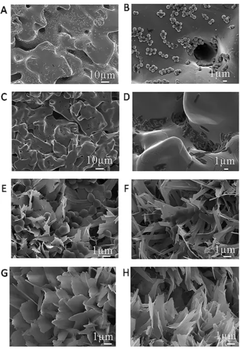
These findings are in accordance with the measured growth curves, where a concentration of 0.75 mM was sufficient to inhibit S. aureus bacteria growth, in contrast with E. coli, where this concentration needs to be doubled. SEM images of uncoated Ti scaffolds (control) and CaP
coated scaffolds without CHX showed the presence of bacteria (Fig. 7
from A to F).
3.3. Osteoblast-like behavior on biofunctionalized surfaces 3.3.1. Cell adhesion
After the study of the antibacterial properties, the effect of the Fig. 5. Mechanical properties of CaP-coated and non-coated scaffolds: A) Young’s modulus and B) ultimate strength.
Fig. 6. Bacteria growth curves: A) S. aureus, B) E. coli and C) S. aureus after scaffold sterilization with gamma radiation. Table 1
Antibacterial activity of functionalized scaffolds expressed as % of reduction of bacteria adhesion in regards to bare Ti scaffolds.
Conditions Inhibition of bacteria adhesion (%)
S. aureus E. coli
CaP+1.5mMCHX 73 ± 3 70 ± 2
presence of CHX on SaOS-2 cells was evaluated. It has been reported in literature that CHX is cytotoxic in vitro when SaOS-2 cells are exposed to
concentration of CHX (0.01%, in medium) for 1 min [40]. For that
reason, to observe the osteoblast-like SaOS-2 cells behavior in contact with functionalized scaffolds, samples were incubated for 6 h and the number, spreading and morphology of adhered cells was evaluated. Results showed that cell adhesion on the surface of scaffolds loaded with 1.5 mM of CHX into the electrolyte solution was statistically similar to
that of Ti scaffolds without coating (Fig. 8A). These values were
statis-tically lower compared to scaffolds coated with CaP without CHX. Although the capacity of SaOS-2 cells to adhere to the CaP surface is reduced when the coating is loaded with 1.5 mM of CHX, the effect of the presence of CHX is probably compensated by the cell adhesion potential
showed on CaP coating [26].
Cells spreading and morphology were further studied in terms of cell
area (Fig. 8B). These studies revealed that cells spreading was
signifi-cantly promoted on CaP and CaP+1.5 mM coatings, compared to Ti
scaffolds (control). In contrast, higher concentrations of CHX (3 mM in the electrolyte solution) yielded a reduction of both cell adhesion and cell spreading.
Finally, SEM and fluorescence images were used to visualize cells on
scaffolds surface (Fig. 8C and Fig. 9B). SEM images corroborated the
results reported previously. Increasing the CHX concentration from 1.5 mM to 3 mM yielded to a reduction in cell adhesion and spreading. For that reason CaP+1.5mMCHX condition was considered the optimal for reaching a compromise between cell adhesion and antibacterial response.
3.3.2. Confocal imaging analysis
Even though the difficulty of acquiring confocal imaging of opaque samples, images were obtained by confocal microscopy taking the advantage of the Ti and CaP crystals light reflection on the prepared scaffolds. The images revealed how cells were distributed on treated and
untreated samples (Fig. 9). Combining both images offer a valuable
Fig. 7. SEM images of: Ti scaffolds without coating tested against S. aureus (A and B) and E. coli (C and D). SEM images of CaP coated surfaces without CHX exposed
information about cell distribution on Ti scaffolds. Interestingly, cells were more prone to adhere throughout the surface of the coated fila-ments of the scaffolds without CHX in comparison with uncoated
scaf-folds, where cells were attached to the lateral part of the rods (Fig. 9A
and B). This can be due to a dual effect that may occur during cells seeding. Coated surfaces may facilitate cell anchoring due to both
chemical interactions and coating morphology [41].
Higher magnification images (e.g. Fig. 9B circular insert) confirmed
that for the CaP+1.5mMCHX condition, cells are spread, which means that this CHX concentration does not inhibit cell adhesion.
3.4. In vitro drug release
Once the antibacterial properties and the cell-adhesive response of scaffolds loaded with 1.5 mM CHX were tested, efforts were focused on studying the release behavior of this condition. The total amount of CHX
loaded to the coating was found to be 136.8 ± 1.6 μg/mL. This amount is
significantly higher than the CHX loading measured in a previous research where smooth Ti surfaces were functionalized with a similar CaP coating, with a total amount of 45 ± 19 µg/mL CHX loaded in the
coating [16]. The higher concentration of CHX on Ti scaffolds may be a
consequence of the increased current density in the pulsed electrode-position and the increased specific area of the scaffold when compared to the previous study, promoting a higher CHX loading. Because of the increased CHX presence in the coating, when comparing the bacterial
growth curves obtained in the present study (Fig. 6) with those reported
on smooth Ti surfaces [16], only half of the concentration of CHX is
required in the electrolyte in order to load enough antiseptic in the coating for inhibiting bacterial growth. Besides, the release of CHX
maintains antibacterial concentrations for more than 14 days (Fig. 10B),
a significant improvement when compared to the previous study, where samples released more than 80% of the CHX in less than 6 days. This result is even more significant when considering that a high surface roughness (as that of the present Ti scaffolds) is more suitable for
mi-crobial colonization [50]. The cumulative release curve presented a
burst release for the first 12 h with 52% of CHX released (Fig. 10A).
Since most surgical infections are believed to occur during the first 6 h after implantation, these results may ensure a noteworthy effect against
implant associated infection [42]. More than 1 week afterwards, CHX
was still released from the coating although the increase was less pronounced.
In order to understand the release mechanism involved, different models were applied to the first 60% of the CHX release curve.
Korsmeyer-Peppas model (KP) can be used to study the limiting drug
release mechanism [51,52]. To this end, the concentration of drug
released was correlated to Eq. (8), where Mt is the drug amount released
at time t, M∞ is the maximum amount released from the coated scaffold,
k is a constant incorporating structural and geometric characteristics of
the drug dosage form, and n is the released exponent that is character-istic of the limiting transport mechanism. Values of n lower than 0.5 is Fig. 8. A) Adhesion and B) cell spreading of SaOS-2 cells on Ti and functionalized Ti scaffolds. C) SEM images of Ti and coated surfaces after 4 h incubation (scale bar
attributed to pseudo-Fickian diffusion, whereas values from 0.5 to 1.0
correspond to non-Fickian transport [43]. Mt/M∞ was obtained for each
specimen and averaged for each condition [44].
Mt/M∞ ktn (8)
Results from KP model showed that the value of n was lower than 0.5 showing that pseudo-Fickian diffusional mechanism controlled the
release of CHX from coating (Table 2) [45]. However, since resulting
squared multiple correlation coefficient R2 for KP model was relatively
low, it was necessary to deepen the understanding of the mechanisms of CHX release by studying another model as Kopcha.
Kopcha model can provide insights regarding the contribution of the diffusion (A) and erosion (B) mechanisms. When the calculated ratio A/
B is higher than 1, the contribution of the diffusion is predominant (Eq. (9)).
Mt At0.5+Bt (9)
Fig. 9. Representative images obtained by confocal microscopy of stained SaOS-2 cells on A) Ti scaffolds, B) CaP+1.5mMCHX and C) CaP+3mMCHX scaffolds. Scale
bar 100 μm (10 μm for the circular insert image).
Fig. 10. A) Cumulative release of CHX from CaP+1.5mMCHX scaffolds and B) CHX released at each time point. Broken lines show CHX MIC values for (1) E. coli and
(2) S. aureus.
Table 2
Parameters obtained from Korsmeyer-Peppas and Kopcha modelling of CHX release from CaP+1.5mMCHX samples.
Korsmeyer-Peppas model Kopcha model
n R2 A/B R2
In this model, the A/B ratio obtained showed that although the presence of the erosion phenomena, it is the diffusion mechanisms that
prevail and lead to the release of CHX [45]. Moreover, this model
pro-vided a better goodness of fit for the studied condition (Table 2).
The amount of CHX released at each time point was found to be
al-ways above the MIC of S. aureus (3 μg/mL) and E. coli (5 μg/mL)
(Fig. 10B) [25]. This is a relevant result, since sub-MIC doses can lead to the risk of resistance. It worth mentioning that the protocol to quantify the CHX release was based on the total replacement of the medium at each time point. Replacement of total medium produces a higher gradient of concentration closed to the substrate compared to replacing only half of the medium. J. Barros et al. studied this effect on CHX- loaded nanohydroxyapatite by adsorption, and observed slower
release kinetics when only half of the medium was replaced [25]. Thus,
it is important to highlight that for electrochemical co-deposition strategy, even with a total replacement protocol a sustained released is achieved above the MIC of both bacteria strains. Moreover, regarding the loading process, it is worth mentioning that adsorption strategies are performed in two steps, first the calcium phosphate layer is prepared and subsequently samples are immersed in a solution of CHX. For that
reason, the complete process can take place in several hours [25,46]. In
contrast, the present study described a one-step process where during the formation of CaP layer, the CHX is co-deposited. More specifically, the loaded coating can be produced in only 30 min.
4. Conclusion
In this work, DIW printed scaffolds have been manufactured with improved mechanical properties compared with previous studies. Moreover, scaffolds have been successfully coated with a pulsed elec-trodeposition process achieving a uniform CaP layer both on the inner and outer the surface of the scaffold. In addition, biofunctionalized scaffolds demonstrated antibacterial activity against Gram-positive and Gram-negative bacteria strains, even after γ-irradiation. Cell culture tests also showed that CHX-loaded scaffolds presented a cell adhesion similar to that of Ti scaffolds.
Therefore, the proposed strategy can efficiently improve orthopedic implants in terms of reaching bone-like and biointegration properties while reducing infections around the implant.
CRediT authorship contribution statement
Elia Vidal: Conceptualization, Formal analysis, Investigation, Methodology, Resources, Writing - original draft, Writing - review & editing. Jordi Guillem-Marti: Data curation, Resources, Writing - re-view & editing. Maria-Pau Ginebra: Funding acquisition, Project administration, Resources, Supervision, Writing - review & editing. Christ`ele Combes: Methodology, Resources, Writing - review & editing. Elisa Rup´erez: Conceptualization, Funding acquisition, Resources, Writing - review & editing. Daniel Rodriguez: Conceptualization, Funding acquisition, Methodology, Resources, Writing - review & editing.
Declaration of competing interest
The authors declare that they have no known competing financial interests or personal relationships that could have appeared to influence the work reported in this paper.
Acknowledgments
The authors thank the Generalitat de Catalunya financial support (SGR 2017 SGR1165), the Spanish Government for financial support through project RTI2018-098075-B-C21 (MINECO/FEDER), co-funded by the EU through European Regional Development Fund, BIO-ACTISURF project no. 14054394 of the R´egion Midi-Pyr´en´ees and COST
Action Ipromedai TD1305. EV acknowledges the FI-DGR scholarship and MPG the ICREA Academia Prize, both by the Generalitat de Catalunya.
Appendix A. Supplementary data
Supplementary data to this article can be found online at https://doi.
org/10.1016/j.surfcoat.2020.126557. References
[1] S. Wu, X. Liu, K.W.K. Yeung, C. Liu, X. Yang, Biomimetic porous scaffolds for bone tissue engineering, Mater. Sci. Eng. R Reports 80 (2014) 1–36.
[2] M. Geetha, A.K. Singh, R. Asokamani, A.K. Gogia, Ti based biomaterials, the ultimate choice for orthopaedic implants - a review, Prog. Mater. Sci. 54 (2009) 397–425.
[3] W. Wang, C.K. Poh, Titanium alloys in orthopaedics, in: J. Sieniawski (Ed.), Titanium Alloys - Advances in Properties Control, IntechOpen, 2013, pp. 1–20. [4] B.D.C. Dunand, Processing of titanium foams, Adv. Eng. Mater. 6 (2004) 369–376. [5] K. Osakada, M. Shiomi, Flexible manufacturing of metallic products by selective
laser melting of powder, Int. J. Mach. Tools Manuf. 46 (2006) 1188–1193. [6] J. Parthasarathy, B. Starly, S. Raman, A. Christensen, Mechanical evaluation of
porous titanium (Ti6Al4V) structures with electron beam melting (EBM), J. Mech. Behav. Biomed. Mater. 3 (2010) 249–259.
[7] H.N. Chia, B.M. Wu, Recent advances in 3D printing of biomaterials, J. Biol. Eng. 9 (2015) 4.
[8] J.P. Li, J.R. De Wijn, C.A. Van Blitterswijk, K. De Groot, The effect of scaffold architecture on properties of direct 3D fiber deposition of porous Ti6Al4V for orthopedic implants, J. Biomed. Mater. Res. - Part A 92 (2010) 33–42. [9] E. Vidal, D. Torres, J. GuillemMarti, G. Sconti, J.M. Manero, M.P. Ginebra,
D. Rodríguez, E. Rup´erez, Titanium scaffolds by direct ink writing: fabrication and functionalization to guide osteoblast behavior, Metals 10 (2020) 1156. [10] A. Civantos, E. Martinez-Campos, V.M. Ramos, C. Elvira, A. Gallardo,
A. Abarrategi, Titanium coatings and surface modifications: towards clinically useful bioactive implants, ACS Biomater. Sci. Eng. 3 (2017) 1245–1261. [11] J. Guillem-Marti, N. Cinca, M. Punset, I. García, F.J. Gil, J.M. Guilemany, S. Dosta,
Porous titanium-hydroxyapatite composite coating obtained on titanium by cold gas spray with high bond strength for biomedical applications, Colloids Surfaces B Biointerfaces 180 (2019) 245–253.
[12] G. Bezzi, G. Celotti, E. Landi, T.M.G. La Torretta, I. Sopyan, A. Tampieri, A novel sol-gel technique for hydroxyapatite preparation, Mater. Chem. Phys. 78 (2003) 816–824.
[13] S.V. Dorozhkin, Calcium orthophosphate coatings, films and layers, Prog. Biomater. 1 (1) (2012).
[14] Y. Abe, T. Kokubo, T. Yamamuro, Apatite coating on ceramics, metals and polymers utilizing a biological process, J. Mater. Sci. Mater. Med. 1 (1990) 233–238.
[15] F.J. García-Sanz, M.B. Mayor, J.L. Arias, J. Pou, B. Le´on, M. P´erez-Amor, Hydroxyapatite coatings: a comparative study between plasma-spray and pulsed laser deposition techniques, J. Mater. Sci. Mater. Med. 8 (1997) 861–865. [16] E. Vidal, J. Buxadera-Palomero, C. Pierre, J.M. Manero, M.P. Ginebra, S. Cazalbou,
C. Combes, E. Rup´erez, D. Rodriguez, Single-step pulsed electrodeposition of calcium phosphate coatings on titanium for drug delivery, Surf. Coat. Technol. 358 (2018) 266–275.
[17] H.X. Wang, S.K. Guan, X. Wang, C.X. Ren, L.G. Wang, In vitro degradation and mechanical integrity of Mg-Zn-Ca alloy coated with Ca-deficient hydroxyapatite by the pulse electrodeposition process, Acta Biomater. 6 (2010) 1743–1748. [18] T. Li, L. Ling, M. Lin, H. Peng, H. Ren, Recent advances in multifunctional
hydroxyapatite coating by electrochemical deposition, J. Mater. Sci. 55 (2020) 6352–6374.
[19] M.S. Chandrasekar, M. Pushpavanam, Pulse and pulse reverse plating- conceptual, advantages and applications, Electrochim. Acta. 53 (2008) 3313–3322. [20] M.J. Liu, M. Zhang, X.F. Zhang, G.R. Li, Q. Zhang, C.X. Li, C.J. Li, G.J. Yang,
Transport and deposition behaviors of vapor coatings materials in plasma spray- physical vapor deposition, Appl. Surf. Sci. 486 (2019) 80–92.
[21] M.P. Ginebra, C. Canal, M. Espanol, D. Pastorino, E.B. Montufar, Calcium phosphate cements as drug delivery materials, Adv. Drug Deliv. Rev. 64 (2012) 1090–1110.
[22] L. Zhao, P.K. Chu, Y. Zhang, Z. Wu, Antibacterial coatings on titanium implants, J. Biomed. Mater. Res. - Part B Appl. Biomater. 91 (2009) 470–480.
[23] M. Stigter, J. Bezemer, K. De Groot, P. Layrolle, Incorporation of different antibiotics into carbonated hydroxyapatite coatings on titanium implants , release and antibiotic efficacy 9 (2004) 127–137.
[24] A.A. Campbell, L. Song, X.S. Li, B.J. Nelson, C. Bottoni, E.S. DeJong, Development, characterization, and anti-microbial efficacy of hydroxyapatite-chlorhexidine coatings produced by surface-induced mineralization, J. Biomed. Mater. Res. 53 (2000) 400–407.
[25] J. Barros, L. Grenho, M.H. Fernandes, C.M. Manuel, L.F. Melo, O.C. Nunes, F. J. Monteiro, M.P. Ferraz, Anti-sessile bacterial and cytocompatibility properties of CHX-loaded nanohydroxyapatite, Colloids Surfaces B Biointerfaces 130 (2015) 305–314.
[26] C. Souza, A. Colombo, R. Souto, C. Silva-Boghossian, J. Granjeiro, G. Alves, A. Rossi, M.H. Rocha-Leao, Adsorption of chlorhexidine on synthetic
hydroxyapatite and in vitro biological activity, Colloids Surfaces B Biointerfaces 87 (2011) 310–318.
[27] ISO 13314, Mechanical Testing of Metals — Ductility Testing — Compression Test for Porous and Cellular Metals, 2011.
[28] C. Labay, J. Buxadera-Palomero, M. Avil´es, C. Canal, M.P. Ginebra, Modulation of release kinetics by plasma polymerization of ampicillin-loaded β-TCP ceramics, J. Phys. D. Appl. Phys. 49 (2016), 304004.
[29] M. Hoyos-Nogu´es, F. Velasco, M. Ginebra, J.M. Manero, F.J. Gil, C. Mas-Moruno, Regenerating bone via multifunctional coatings: the blending of cell integration and bacterial inhibition properties on the surface of biomaterials, ACS Appl. Mater. Interfaces 9 (2017) 21618–21630.
[30] C. Rey, O. Marsan, C. Combes, C. Drouet, D. Grossin, S. Sarda, Characterization of calcium phosphates using vibrational spectroscopies, in: Advances in Calcium Phosphate Biomaterials, Springer, Berlin, Heidelberg, 2014, pp. 229–266. [31] R. Drevet, H. Benhayoune, Electrochemical deposition of calcium phosphate
coatings on a prosthetic titanium alloy substrate, in: R. Heimann (Ed.), Calcium Phosphate: Structure, Synthesis, Properties, and Applications, Nova Science Publishers, 2012, pp. 231–252.
[32] S.O.R. Sheykholeslami, J. Khalil-Allafi, L. Fathyunes, Preparation, characterization, and corrosion behavior of calcium phosphate coating electrodeposited on the modified nanoporous surface of NiTi alloy for biomedical applications, Metall. Mater. Trans. A 49 (2018) 5878–5887.
[33] D.N. Da Rocha, M.H.P. Da Silva, J.B. De Campos, R.L.S.B. Marçal, D.Q. Mijares, P. G. Coelho, L.R. Cruz, Kinetics of conversion of brushite coatings to hydroxyapatite in alkaline solution, Journal of Materials Research and Technology 7 (2018) 479–486. [34] J. Fornell, Y.P. Feng, E.M. Pellicer, M.D. Bar´o, S. Surinach, J. Sort, Mechanical
behaviour of brushite and hydroxyapatite coatings electrodeposited on newly developed FeMnSiPd alloys, J. Alloys Compd. 729 (2017) 231–239.
[35] D. Gopi, J. Indira, L. Kavitha, A comparative study on the direct and pulsed current electrodeposition of hydroxyapatite coatings on surgical grade stainless steel, Surf. Coatings Technol. 206 (2012) 2859–2869.
[37] Z.Z. Fang (Ed.), Sintering of Advanced Materials: Fundamentals and Processes, first ed., Woodhead Publishing Limited, 2010.
[38] H. Danninger, R.D.O. Calderon, C. Gierl-Mayer, Powder Metallurgy and Sintered Materials, Ullmann’s Encyclopedia of Industrial Chemistry, 2017.
[39] D.A.C. Heesterbeek, N.I. Martin, A. Velthuizen, M. Duijist, M. Ruyken, R. Wubbolts, S.H.M. Rooijakkers, B.W. Bardoel, Complement-dependent outer
membrane perturbation sensitizes Gram-negative bacteria to Gram-positive specific antibiotics, Sci. Rep. 9 (2019) 3074.
[40] M. Giannelli, F. Chellini, M. Margheri, P. Tonrlli, A. Tani, Effect of chlorhexidine digluconate on different cell types: a molecular and ultrastructural investigation, Toxicol. in Vitro 22 (2007) 308–317.
[41] Y. Su, I. Cockerill, Y. Zheng, L. Tang, Y. Qin, D. Zhu, Biofunctionalization of metallic implants by calcium phosphate coatings, Bioact. Mater. 4 (2019) 196–206. [42] M. Gimeno, P. pinczowski, M. P´erez, A. Giorello, M.A. Martínez, J. Santamarí,
M. Arruebo, L. Luj´an, A controlled antibiotic release system to prevent orthopedic- implant associated infections: an in vitro study, Eur. J. Pharm. Sci. 96 (2015) 264–271.
[43] H. Noukrati, S. Cazalbou, I. Demnati, C. Rey, A. Barroug, C. Combes, Injectability, microstructure and release properties of sodium fusidate-loaded apatitic cement as a local drug-delivery system, Mater. Sci. Eng. C 59 (2016) 177–184.
[44] P. Costa, J.M. Sousa Lobo, Modeling and comparison of dissolution profiles, Eur. J. Pharm. Sci. 13 (2001) 123–133.
[45] G.R. Biswas, S.B. Majee, Modeling of drug-difusion kinetics of amoxicillin trihydrate from buccal tablets, Int. J. Pharm. Bio Sci. 6 (2015) 859–866. [46] S. Ghosh, V. Wu, S. Pernal, V. Uskokovic, Self-setting calcium phosphate cements
with tunable antibiotic release rates for advanced antimicrobial applications, ACS Appl. Mater. Interfaces 8 (2016) 7691–7708.
[47] I.M. Mehdawi, A. Young, Antibacterial composite restorative materials for dental applications. Biomaterials and Medical Device - Associated Infections, Woodhead Publishing, 2015, pp. 199–221.
[48] E.F. Morgan, G.U. Unnikrisnan, A.I. Hussein, Bone mechanical properties in healthy and diseased states, Annu. Rev. Biomed. Eng. 20 (2019) 119–143. [49] H. Ketata, F. Affes, M. Kharrat, M. Dammak, A comparative study of tapped and
untapped pilot holes for bicortical orthopedic screws – 3D finite element analysis with an experimental test, Biomed. Eng.-Biomed. Tech. 64 (2019) 563–570. [50] L. Damiati, M.G. Eales, A.H. Nobbs, B. Su, P.M. Tsimbouri, M. Salmeron-Sanchez,
M.J. Dalby, Impact of surface topography and coating on osteogenesis and bacterial attachment on titanium implants, J. Tissue Eng. 9 (2018) 1–16. [51] N.A. Peppas, Analysis of Fickian and non-Fickian drug release from polymers,
Pharm. Acta Helv. 60 (1985) 110–111.
[52] R.W. Korsmeyer, R. Gurny, E. Doelker, P. Buri, N.A. Peppas, Mechanisms of solute release from porous hydrophilic polymers, Int. J. Pharm. 15 (1983) 25–35.