To cite this version :
Amari, Ahmed and Mifdaoui, Ahlem and
Frances, Fabrice and Lacan, Jérôme and Rambaud, David and
Urbain, Loic
AeroRing: Avionics Full Duplex Ethernet Ring with
High Availability and QoS Management.
(2016)
In: Proceedings of European Congress on Embedded Real Time
Software and systems 2016, 27 January 2016 - 29 January 2016
(Toulouse, France)
OATAO is an open access repository that collects the work of Toulouse researchers and
makes it freely available over the web where possible.
This is an author-deposited version published in :
http://oatao.univ-toulouse.fr/
Eprints ID : 14461
Any correspondance concerning this service should be sent to the repository
administrator:
[email protected]
AeroRing: Avionics Full Duplex Ethernet Ring with
High Availability and QoS Management
A. AMARI
1, A. MIFDAOUI
1, F. FRANCES
1, J. LACAN
1, D. RAMBAUD
2, L. URBAIN
31
University of Toulouse-ISAE, France,
2BetaTECH, France,
3ECA Group, France,
Abstract—The avionics standard AFDX has been introduced to provide high speed communication for new generation aircraft. However, this switched network is deployed in a full redundant way, which leads to significant quantities of wires. To overcome this limitation, a new avionic communication network, called AeroRing, is proposed in this paper to decrease the wiring weight, while guaranteeing the required performance and safety levels. AeroRing is based on a Gigabit Ethernet technology and implements a daisy-chain wiring scheme on a Full Duplex ring topology. First, the main features of such a proposal, and particularly the QoS and robustness management, are detailed. Then, numerical results of some Performance Indicators (PI) are illustrated to highlight its ability to guarantee the avionics requirements.
Keywords-Avionics, Real-Time Ethernet, Ring topology, QoS, Performance, Safety.
I. INTRODUCTION
The inherent complexity and bandwidth requirement of avionics communication architectures are increasing due to the growing number of interconnected end-systems and the expansion of exchanged data. The Avionics Full Duplex Switched Ethernet (AFDX) [1] has been introduced to provide high speed communication (100Mbps) for new generation aircraft. However, this switched network is deployed in a full redundant way, which leads to significant quantities of wires, and thus increases weight and integration costs. For instance, the A380 contains 500 km of cables [2].
To cope with these emerging issues, an avionics implementation reducing wires will clearly improve the efficiency and reliability of aircraft through decreasing the integration complexity, and reducing fuel consumption and maintenance costs. Therefore, a new avionic communication network, called AeroRing1, based on a Gigabit Ethernet technology and implementing a daisy-chain wiring scheme on a Full Duplex ring topology, is proposed in this paper to enhance performance, while guaranteeing a high safety level for avionics applications.
Nowadays, Ethernet technology is considered as one of the most cost effective solutions allowing scalable and arbitrary topologies, and supporting high speed communication and Quality of Service (QoS) requirements. Various approaches have been proposed to guarantee real-time communications 1Aeroring is co-funded by the European Union. Europe is involved in
Midi-Pyrenees through the European Funds for Regional Development.
on top of Ethernet. The most relevant Real Time Ethernet (RTE) profiles, supporting ring topology and cited in IEC 61784-2 [3], have been described in [4]. However, most of these existing solutions are optimized for specific use cases and present some limitations in terms of:
• resource utilization efficiency, since concurrent access to the medium is generally not allowed due to their implemented control mechanisms, e.g., master/slaves or TDMA;
• flexibility, as only pre-planned cyclic communications are enabled, and require an efficient synchronization protocol;
• robustness management, because of the centralized fault management, classically provided by the master or network manager, which is considered as a central point of failure.
Hence, the main contribution of this work is the specifications of a new RTE protocol, AeroRing, which bridges the gap between existing RTE solutions, supporting ring topology, to enhance the resource utilization efficiency, the system flexibility and robustness management; in addition to guaranteeing the key requirements of safety-critical domains, such as avionics.
In the next section, we review the most relevant RTE solutions supporting ring topology and relate them to our proposal. Afterwards, the main innovative features of AeroRing, and its basic functionalities including the QoS and robustness management, are detailed in Sections 3 and 4, respectively. Finally, in Section 5, some numerical results on performance and reliability indicators of such a proposal are presented, to highlight its ability vs avionics requirements.
II. RELATEDWORK
During the last two decades, a wide range of RTE solutions have been proposed by industrials and academia. The most relevant ones have been cited in the document IEC 61784-2 [3], which in addition introduces a set of Performance Indicators (PIs) to evaluate the RTE networks abilities. In this section, we first describe the most effective PIs and the main requirements to fulfill for safety-critical applications. Then, based on these requirements, we conduct a benchmarking of AeroRing and the most relevant IEC profiles supporting ring
Protocols Costs Reliability Availability Performance Complexity Ethernet Compatibility EtherCAT High Medium High Very High High No PROFINET IRT High Medium High High High No Ethernet/IP with DLR Medium High Medium Medium Low Yes AeroRing High High Very High High Low Yes
TABLE I
BENCHMARKING OFRTESOLUTIONS SUPPORTING RING TOPOLOGY
Characteristic EtherCAT PROFINET IRT EDLR AERORING Rate (Mbps) 100 100 100 1000
Topology Bus or ring Bus or ring Daisy-chain ring Daisy-chain ring Media 100Base-TX 100Base-TX 100Base-TX 1000BASE-TX Control Mechanism Master/slaves Master/slaves DLR Event-triggered with SP policy Robustness management centralized centralized centralized distributed
QoS management no no yes yes Standardization Open standard Open standard By OADV Open specifications
Pros On-the-fly transmission Cut-through transmission Efficient faults detection Cut-through transmission Short transmission cycle Short transmission cycle QoS Management Short transmission cycle
QoS Management Distributed Fault Management Cons Specific devices Specific devices Complexity due to integrated switches Not standardized yet
Central point of failure Central point of failure High latency TABLE II
SPECIFICATIONSCOMPARISON OFRTESOLUTIONS SUPPORTING RING TOPOLOGY
topology.
A. Performance Indicators and Requirements
Among the specified PIs in [3], we consider the following main ones:
• Maximum Delivery Time, indicating ”the time needed to convey an APDU containing data (message payload) that has to be delivered in real-time from one node (source) to another node (destination)” when considering the worst-case scenario.
• Fault Detection Time, indicating the maximum time needed to all nodes to be aware of failure.
• Redundancy recovery time, indicating ”the maximum time from failure to become fully operational again in case of a single permanent failure”.
Furthermore, we consider an additional PI, which is the maximum backlog to evaluate the memory utilization within network components. Numerical results concerning these aforementioned PIs of AeroRing are illustrated in Section V. In addition to these PIs, RTE networks must fulfill a set of key requirements, which reveal particularly effective for many safety-critical applications, and particularly for avionics. These requirements concern both technical and costs aspects. The technical requirements are mainly the timeliness and the accuracy of delivered data, in addition to the reliability and availability of the communication network. Furthermore, the choice of the RTE solution shall be efficient to meet the design requirements for the least amount of money. Therefore, the IEEE802.3 compatibility, a minimized configuration effort and reduced implementation costs are among the most important
issues to guarantee. These requirements will be considered to benchmark AeroRing against the most relevant IEC profiles, supporting ring topology and cited in IEC 61784-2 [3]. B. Benchmarking Most Relevant IEC profiles
Among the RTE solutions in [3], there is a first class with an implementation at the network layer, e.g., P-NET, V-NET, Modbus-RTPS and Ethernet/IP. These solutions are usually easier to implement and configure, but they lead at the same time to important latencies (about 10ms), which makes them more effective for soft real-time applications. Then, there is a second category providing a realization on top of the MAC layer while keeping the IEEE802.3 compatibility, e.g., TCNET, Ethernet/IP with Device Level Ring (DLR) and PowerLink, or modifying the standard implementation, e.g., EtherCAT and Profinet IRT. In this paper, we focus only on the most relevant RTE solutions supporting ring topology, and particularly EtherCAT, Profinet IRT and Ethernet/IP with DLR.
EtherCAT is defined by Beckhoff GmbH and supported by the EtherCAT Technology Group (ETG). It implements a master/ slave mechanism on top of Fast Ethernet (100Mbps). The main particularity of EtherCAT is the on-the-fly forwarding technique, which allows the slaves to insert the data requested by the master directly in the frame crossing couplers step by step. The EtherCAT frame is transmitted from the first slave to the last, and then back in the opposite direction to the master. This protocol provides interesting real-time performances due to the on-the-fly mechanism.
However, the main drawbacks of this technology consist of: • the specificity of the EtherCAT devices, which increases
the implementation costs and the configuration efforts; • a central point of failure (i.e. the master) decreasing the
reliability level.
PROFINET IRT (Isochronous Real-Time) is an extended version of PROFINET, which supports real time communications. It is a master/ slave network, based on cyclic communication handling two communication channels: isochronous and asynchronous. These latter are used by slaves to transmit real-time and non real-time data, respectively. The data is relayed using ”Cut-through” to reduce the processing time. These functionalities require specific equipments and an accurate synchronization protocol. This protocol has similar pros and cons than EtherCAT due to its incompatibility with IEEE 802.3 and its master/slave mechanism.
Device Level Ring (DLR) protocol was introduced in 2008 by OADV organization to support hard real-time communication with Ethernet/IP. DLR is based on a ring controller, called active ring supervisor, which collects data from the other interconnected nodes on only one port to avoid infinite traffic loop, except some specific frames, i.e., beacons. Each equipment has two Ethernet interfaces and an integrated switch, which implements Store & Forward mechanism and Static Priority service policy. Moreover, fault detection and reconfiguration mechanisms are handled within the controller via specific messages, i.e., beacon and announce. This protocol has interesting features in terms of reliability due to the fault detection mechanism within the controller, and reduced costs due to standard devices. However, the non-nominal case needs the reconfiguration of the supervisor, which increases the configuration effort. Furthermore, integrated switches based on Store & Forward mechanism induce high transmission latencies, which decrease the offered real-time performance and availability levels.
The benchmarking of these RTE solutions vs the main identified requirements in Section II-A is illustrated in Table I. EtherCAT and Profinet IRT imply higher costs due to the specificity of the implemented devices, and lower reliability due to the master/slaves mechanism (i.e. inducing a central point of failure), than Ethernet/IP with DLR. This latter is based on standard devices and implements fault detection and reconfiguration mechanisms, which enhance costs and reliability. Concerning real-time performance, EtherCAT and Profinet IRT allow very short latencies due to on-the-fly and Cut Through mechanisms, whereas Ethernet/IP with DLR induces high latencies because of the Store & forward one. Moreover, these transmission latencies have a direct effect on the fault detection time, and consequently the availability level. Hence, the offered real-time performance and availability levels of EtherCAT and Profinet IRT are higher than Ethernet/IP. It is worth noting that each RTE solution satisfies selected requirements better than others, but there is no best solution in terms of all the requirements.
Our objective is to specify a new RTE solution, AeroRing, which bridges the gap between these aforementioned RTE solutions, to guarantee the high reliability level of Ethernet/IP with DLR and the high real-time performance and availability levels of EtherCAT and Profinet IRT. Moreover, this new RTE solution has to keep the IEEE802.3 compatibility and reduce the implementation costs and configuration efforts. Hence, the AeroRing abilities vs the the main identified requirements are illustrated in Table I.
The main innovative features of AeroRing are as following: • Distributed access mechanism, allowing simultaneous data exchange to increase the offered bandwidth and resource usage efficiency;
• Distributed fault management mechanism, avoiding the central point of failure to provide high Reliability and Availabilitylevels;
• Event-triggered communication, enhancing the system flexibility and decreasing the implementation complexity, through avoiding any need of synchronization;
• QoS management, handling heterogeneous data con-straints. This feature is guaranteed through the imple-mentation of a Static Priority (SP) policy supporting four traffic classes: the network management class with the highest priority, the Hard Real Time (HRT) with the second highest priority, the Soft Real Time (SRT) class with medium priority and finally the Non Real Time (NRT) class with the lowest priority.
• QoS-aware routing algorithm, sending HRT on both ports to improve reliability, and the SRT and NRT traffic classes on the shortest path to enhance resource usage efficiency;
• Compatibility with IEEE802.3, guaranteeing an easy deployment process and a cost-effective integration. Table II illustrates a summary of the main characteristics of AeroRing and the aforementioned RTE solutions, and particularly the pros and cons of each solution.
III. WHAT ISAERORING
In this section, we present the main fundamental concepts of AeroRing network, including T-AeroRing features and data processing.
A. T-AeroRing Features
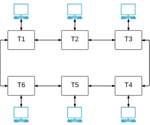
As illustrated in Fig. 1, AeroRing network implements a daisy-chain wiring scheme on top of a Full Duplex ring topology. It allows any ”Ethernet-compliant” equipment to transmit its data via a specific end-system, named T-AeroRing. Each transmitted packet will be forwarded from one T-AeroRing to another until reaching the final destination, and some particular cases will be detailed in the next section.
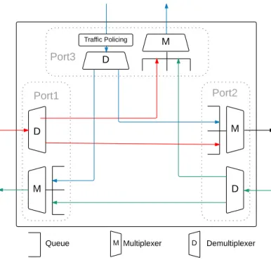
The T-AeroRing is a specific 3 ports Full Duplex Ethernet switch having the internal architecture illustrated in Figure 2, and the following main characteristics:
• Cut-Through forwarding technique: the T-AeroRing starts forwarding the packet just after its identification, i.e. only the header of each packet is decoded to determine its destination port. This technique guarantees shorter transmission latency than the ”Store and Forward” technique (implemented within Ethernet/IP), which waits until the complete reception of the packet before forwarding it to the destination port;
• Static Priority service policy packets are queued in each output port of T-AeroRing according to their priorities. A queue is selected for transmission only if all traffic classes queues with higher priorities are empty. Then, for each queue, the scheduling order is First In First Out (FIFO) with a non-preemptive transmission. Priority is defined according to the IEEE 802.1p standard where the 802.1Q tag (3-bits field) is used to manipulate the four priority classes;
• Traffic policing: To guarantee real-time performance, the T-AeroRing implements traffic policing mechanisms, based on Leaky Bucket method and particularly greedy method [5], to control each traffic class compliance with its predefined contract to avoid the network saturation. These traffic contracts are defined based on the network designer specifications. Each equipment connected to a T-AeroRing should be aware of these traffic contracts, and may apply traffic shaping to ensure the conformity of its generated traffic and avoid being discarded by the traffic policers. Each traffic exceeding its associated contract may be discarded to guarantee the communication determinism;
• QoS-aware routing: unlike COTS Ethernet switches which relay frames on the basis of the address learning process and the Spanning Tree Algorithm, each T-AeroRing builds its routing table on the basis of the network management messages, exchanged between the interconnected T-AeroRings during the initialization phase or when a topology modification occurs (i.e. failure or restoration). Each T-AeroRing implements two routing modes to transmit its generated packets depending on their priorities: (i) sending on both ring ports (Ports 1 and 2 in Fig. 2) for high priority traffic classes, i.e., network management and HRT data, to allow a high reliability level ; (ii) sending on the port corresponding to the shortest path for medium and low priority traffic classes, i.e., SRT and NRT data, to offer a high performance level (i.e. short delay);
• Frame Redundancy Management: Like AFDX
end-systems, the T-AeroRing implements a Frame redundancy management mechanism to detect redundant frames generated by the first routing mode, and to determine whether to deliver the packet to the final destination or drop it because its replica has already been received. In practice, all packets sent on both ring ports are provided with a 2-bytes sequence number field that occurs just before the FCS field, which will be checked at the destination;
• Filtering Function: To avoid infinite packet looping as a result of broadcast communication or erroneous header information, each T-AeroRing implements a filtering function which consists in: (i) eliminating all its generated packets sent on one port and received on the other port. This case occurs for broadcast packets or those with erroneous destination address; (ii) eliminating all received packets with erroneous source address. This verification is possible due to the cut-through technique and the routing table, i.e. an erroneous address does not exist in the routing table.
T1 T2 T3
T6 T5 T4
Fig. 1. AeroRing network
B. Data processing
Based on the description of T-AeroRing ports in Fig. 2, each frame will be processed as follows in the nominal case:
• Any frame received on a network port (1 or 2) is relayed to the other port unless the frame is destined to the connected equipment, or this latter is the frame source. • Any frame received on a network port (1 or 2) destined
to the connected equipment is delivered to it, according to the redundancy management mechanisms.
• Any frame received from the connected equipment is transmitted on one or both network ports depending on its priority: the highest priority traffic class is tagged by a 2-bytes sequence number and transmitted on both ports, while the medium and lowest priorities traffic classes are transmitted on the port corresponding to the shortest path.
D D D M M M Port1 Port2 Port3 Traffic Policing M D
Queue Multiplexer Demultiplexer
Fig. 2. T-AeroRinginternal architecture
IV. NETWORKFUNCTIONALITIES
In this section, we present the main functionalities of AeroRing, including the QoS and robustness management and the auto-configuration mechanisms.
A. Real-Time behavior and QoS Management
The real-time behavior of AeroRing and the timeliness guarantee of the delivered data are favored due to the implemented features within the T-AeroRing. First, the ”Cut Through” forwarding technique allows a short transmission time along the network, which improves the Maximum end-to-end delivery time. Then, the traffic policing mechanism prevents a network saturation by a deficient equipment, which guarantees the communication determinism. Furthermore, the implemented QoS-aware routing algorithm supports the transmission of the SRT and NRT data on the shortest path, which decreases their transmission delays. Finally, the Static Priority policy ensures the temporal isolation between mixed criticality data with various temporal constraints, and guarantees a bounded delay for the HRT traffic class.
On the other hand, AeroRing guarantees QoS management through the implementation of ”Static Priority” policy, which supports the following traffic classes:
1) Control Messages: This traffic class has the highest priority level (N0) and is used for network management issues, such as: (i) building the routing tables of the interconnected T-AeroRings; (ii) the fault detection management; (iii) neighbor status checking. For the two former, the control messages are sent on both ring ports to ensure a high reliability level; whereas for the latter,
the control messages are only sent to the neighbors, if no data to send, to check their status and guarantee a fast fault detection;
2) HRT Messages: this traffic class has the second highest priority level (N1) and is assigned to real-time applications with hard temporal constraints, i.e. the message must be received before its deadline otherwise it is considered lost. This type of messages is sent on both ring ports to ensure a high reliability level, and is identified by a 2-bytes sequence number, essential for the frame redundancy mechanism within the destination T-AeroRing;
3) SRT Messages: this traffic class has the medium priority level (N2) and is assigned to soft real-time applications, such as audio or video transfers. This type of messages is sent on the ring port corresponding to the shortest path to guarantee a high performance level, i.e. short transmission delay;
4) NRT Messages: this traffic class has the lowest priority level (N3) and is assigned to non real-time applications, such as file transfer. This type of messages is sent on the ring port corresponding to the shortest path to guarantee a high performance level;
It is worth noting that the AeroRing is compatible with the IEEE 802.3 standard and each T-AeroRing can deliver any type of ”802.1x-compliant” frame from the equipment. Hence, if the frame does not include the 802.1Q tag, then it will be treated as a NRT data frame (N3), and transmitted on the ring port corresponding to the shortest path.
B. Auto-Configuration Mechanism
To reduce the configuration effort for the network designer and facilitate this new RTE solution adoption in the market, AeroRing offers an auto-configuration service until all the T-AeroRings become operational. This service is based on a simple address assignment method and a dynamic network topology discovery process. The address assignment of the connected T-AeroRings method consists in assigning the equipment MAC address to its corresponding T-AeroRing, when it joins the network. This fact facilitates the communication between the connected equipments and avoids a heavy translation addresses step.
At the beginning, each T-AeroRing which is not connected to an equipment, has a default address MAC. Then, each freshly connected T-AeroRing enters a network topology dis-covery phase and behaves as follows:
• transmit periodically control messages on each ring port until receiving a control message from another T-AeroRing on the same port. This means that it has a neighbor on that side and it is no longer the last node of
the segment. This period can be tuned according to the application requirements by the network designer. • stop transmitting control messages when detecting both
neighbors. Hence, the control messages transmission stops when the ring loop is closed.
Furthermore, on the basis of these control messages exchanged between T-AeroRings, each T-AeroRing builds a routing table per port. These routing tables allow to select the port corresponding to the shortest path (ports 1 or 2) for a destination. Each exchanged control message contains the list of MAC addresses of the crossed T-AeroRings, according to their physical positions along the network.
Figure 3 shows the structure of a control message. The control messages are identified by the value type of ”0x9000”. Then, the CTL field identifies the type of the control message, where ”0001” is reserved to build the routing tables, and NBAD field is a counter of the MAC addresses, which are inserted in the ADDx fields.
Type Payload
0x9000 CTL NBAD ADD1 ADD2 ... ADDN-1 ADDN
(2) (4 bits) (12 bits) (8) (8) (8) (8) (8)
Fig. 3. Structure of a control message
These control messages to build the routing tables are managed as following:
• at each topology change, i.e. start, failure or restoration, the T-AeroRings detecting this event send a control message on both network ports in broadcast mode with the highest priority, to update the routing tables of the other interconnected T-AeroRings;
• each T-AeroRing contributes in building the routing tables: when receiving the control message, it inserts its MAC address at the end of the list to respect the physical order, increment the NBAD counter, forwards it to the next T-AeroRing and updates its routing table (i.e. inserts MAC addresses of new equipments and deletes the ones that no longer exist) (see the example in Fig. 4).
C. Robustness Management
AeroRing offers a high reliability and availability levels due to its implemented features. First, redundancy management mechanisms are defined for both network and frames. Then, error detection and recovery mechanisms are implemented. Finally, a distributed fault detection and reconfiguration management is supported, which avoids single point of failure. 2 1 6 3 4 5 4 5 4 6,5,4 3,2,1,6,5,4 5,6,1,2,3,4 ______ 3|5 2|6 1|1 6|2 5|3
Fig. 4. Example of routing table building
1) Redundancy Management: AeroRing supports redundant topology where each equipment may be connected to redundant T-AeroRings and transmit its data on two redundant networks (see Fig. 5). These redundant networks might be used in a complementary way, i.e., the packet is sent only on the main network in the nominal case and on the backup one in case of failure; or in a symmetric way, i.e., each packet is replicated and sent on both networks. Each equipment implements a redundancy management mechanisms to identify packets (replicas) that arrive on both networks to consume the packet or drop it because its replica has already been received.
Furthermore, according to the QoS-aware routing algorithm within the T-AeroRing, the HRT traffic is sent on both ring ports to enhance the availability and reliability level. Each T-AeroRing implements a Frame redundancy management to detect redundant frames to determine whether to deliver the packet or drop it.
2) Error Detection and Recovery Mechanisms: Similar to standard Ethernet solution, AeroRing supports the error detection through the FCS field to discard erroneous frames. However, if the error is not detected based on the FCS field, and it occurs on the header, then the frame has to be eliminated from the network to avoid infinite packet looping. Each T-AeroRing implements a filtering function to prevent this phenomena. A frame with an erroneous destination address will be filtered by its source. However, if the source address is incorrect, any T-AeroRing can eliminate the erroneous frame when detecting that the erroneous address does not exist in its routing table.
3) Fault Detection and Reconfiguration Mechanisms: Any T-AeroRing has to consider a connection as down with a neighbor, if it does not receive any message from its neighbor during a certain period called ”detection period”. This detection period can be easily tuned by the network designer. In practice, if a T-AeroRing has no data to transmit to its neighbor, then it announces periodically its status to that neighbor through sending control messages. These latter have the CTL field set to ”0000”, and empty NBAD and ADDx fields (see Fig. 3).
These control messages to announce the status to neighbors are sent periodically when at least one of the following conditions is satisfied:
• The T-AeroRing does not have any data to send on this port during a period called ”announcing period” (this period is less then the detection period that covers in general the reception of more than one control message); • The T-AeroRing did not receive any data or control message from this port for a duration equal to the detection period. In this case, the T-AeroRing indicates to its neighbor through a control message that the connection is considered as down.
When a connection is considered as down by one of the interconnected T-AeroRing, this latter sends a first control message to inform the other T-AeroRings with the CTL code ”0010”, followed by a second control message to update the routing tables (see the example in Fig. 6). A down connection is considered operational again (up), if the T-AeroRing starts receiving frames (data or control) from its neighbor. In this case, it sends a control message to update the routing tables of the other nodes.
It is worth noting the existence of various redundancy protocols for RTE solutions with ring topology, and the most relevant ones in our case are the Distributed Redundancy Protocol (DRP) [6] and the Ring-based Redundancy Protocol (RRP) [7].
The DRP implements similar local fault detection mechanisms than AeroRing, where each equipment can check the status of its neighbors by sending a link test frame
3
2
1
4
5
6
6 1 ______ 3| 2| 1| 6| 4 3 C trl Ctr l ______ |1 |2 |3 |4 ______ 2|6 3| 4| ______ 3|1 4|6 ______ 4|2 |1 |6Fig. 6. Fault detection Mechanism
LinkCheck to detect failures. However, unlike AeroRing, in addition to these local mechanisms, DRP implements a centralized fault detection mechanism to check the ring status in a cyclic manner, i.e., during each cycle, only one equipment can check the ring status via a ring test frame RingCheck, gather and broadcast the information to the rest of equipments. Furthermore, an accurate synchronization protocol is required to manage such a cyclic process.
On the other hand, the RRP implements similar distributed mechanisms than AeroRing to build the routing tables within equipments. However, unlike AeroRing, RRP consists in transforming the ring topology into line topology to avoid infinite packet looping, through selecting two adjacent devices, called Ring Network Managers (RNMs), which disable one of their ports. This choice will clearly deteriorate the reliability level, compared to AeroRing, since sending on both directions becomes forbidden. Moreover, RRP implies higher communication overhead to build the routing tables than AeroRing, i.e., there are as many exchanged messages as equipments to update the routing tables under RRP, whereas only one control message is necessary with AeroRing.
Hence, unlike DRP, AeroRing implements a completely distributed redundancy protocol, based only on local fault detection mechanisms and without any need of synchronization protocol. Furthermore, unlike RRP, the T-AeroRings build autonomously their routing tables with a low induced overhead, and messages can be sent on both directions or only on the shortest path, according to the message class.
V. PERFORMANCE ANDRELIABILITYANALYSIS
In this section, we investigate the offered performance and reliability levels of AeroRing through a representative case study. Therefore, we give first numerical results on some specified PIs, such as the upper bounds on the end-to-end latencies and backlogs, and the maximum detection and recovery times. The detailed analyses of these PIs are beyond the scope of this paper.
A. Case study
We consider the following assumptions: • The links speed is C = 1Gbit/s;
• The network size varies from 4 to 40 nodes (40 is the medium size specified in the IEC document [8] to benchmark RTE solutions);
• All equipments are similar and send the same traffic in broadcast mode;
• Technological latency within the T-AeroRing is 600ns; • Each equipment generates 3 types of traffic classes (TC)
as described in Table III;
• The ”detection period” for fault management is 0.5ms.
It is worth noting that in the broadcast mode, the notion of ”shortest path” does not exist for the traffic SRT and NRT. In this case study, we consider that all the SRT and NRT messages are sent on the same direction, which corresponds to the worst-case scenario in terms of performance, i.e., this choice increases contention.
TABLE III TRAFFICCHARACTERISTICS
TC Payload (byte) Throughput (Kbps) I/O data HRT 64 80 Audio streaming SRT 100 128
File transfer NRT 1000 500
B. Numerical Results
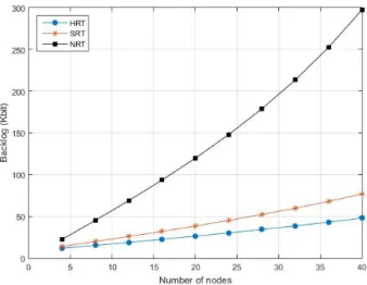
Figures 7 and 8 illustrate the upper bounds on the end-to-end latencies and backlogs, respectively. Obviously, these metrics increase with the network size, since the number of generated messages and crossed nodes increases.
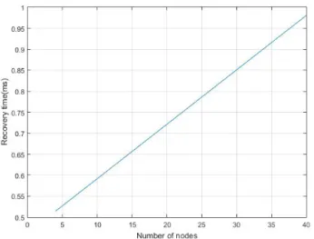
As we can notice, for a network of 40 nodes, the upper bound on the end-to-end latency for the highest priority is less than 2ms, and the maximum backlog is less than 300Kbit. Figures 9 and 10 illustrate the maximum detection and redundancy recovery times. These metrics depends on the length of the control message updating the routing tables, which increases with the number of crossed nodes. For a network of 40 nodes, the maximum detection and recovery times are less than 0.75ms and 1ms, respectively.
Fig. 7. Upper bounds on the end-to-end latencies vs number of nodes
Fig. 8. Upper bounds on backlog vs number of nodes
Fig. 10. Maximum recovery time vs number of nodes
These results show the high performance and reliability levels guaranteed by AeroRing for a medium size network.
VI. CONCLUSION ANDFUTUREWORK
A new RTE solution, called AeroRing, has been proposed in this paper to handle the emerging requirements of new generation aircraft in terms of decreasing the wire complexity and integration costs, and enhancing the real-time performance and availability.
This solution has many advantages, compared to the most relevant RTE solutions supporting ring topology, such as:
• enhancing the performance and the resource usage ef-ficiency due to its distributed access mechanism and its QoS-aware routing algorithm;
• offering high availability and reliability levels through a distributed fault management mechanisms, which avoid any single point of failure;
• improving the network flexibility through event-triggered communication support without any need of synchroniza-tion;
• minimizing the implementation costs due to its compatibility with IEEE 802.3 standard, and the configuration effort through its auto-configuration mechanisms.
AeroRing has been specified to fulfill the avionics requirements, but it can be easily extended for other industrial application fields, such as automation and control. This adaptation will be investigated as a next step of our work. Furthermore, AeroRing consortium is working on the standardization process of such a proposal with open source specifications, to facilitate its adoption in the market.
REFERENCES
[1] “Avionics Full-Duplex Switched Ethernet (AFDX) Network, ARINC Specification 664, Part 7, Aeronautical Radio.”
[2] C. Furse and R. Haupt, “Down to the wire,” Spectrum, IEEE, vol. 38, no. 2, pp. 34–39, 2001.
[3] IEC 61784-2, Digital data communications for measurement and control - Part 2: Additional profiles for ISO/IEC 8802-3 based communication networks in real-time applications, 2010.
[4] M. Felser, “Real-Time Ethernet - Industry Prospective,” Proceedings of the IEEE, vol. 93, 2005.
[5] E. Wandeler, A. Maxiaguine, and L. Thiele, “On the Use of Greedy Shapers in Real-Time Embedded Systems,” Embedded Computing Sys-tems, vol. 11, no. 1, 2012.
[6] IEC 62439-3, Industrial communication networks - High availability automation networks - Part 6: Distributed Redundancy Protocol (DRP). [7] IEC 62439-7, Industrial communication networks - High availability automation networks - Part 7: Ring-based Redundancy Protocol (RRP). [8] IEC 62439-1, Industrial communication networks - High availability