Science Arts & Métiers (SAM)
is an open access repository that collects the work of Arts et Métiers Institute of
Technology researchers and makes it freely available over the web where possible.
This is an author-deposited version published in:
https://sam.ensam.eu
Handle ID: .
http://hdl.handle.net/10985/18099
To cite this version :
Lucas Venancio LIMA, Yann-Philippe CHARLES, Philippe ROUCH, Wafa SKALLI - Limiting
interpedicular screw displacement increases shear forces in screws: A finite element study
-Orthopaedics & Traumatology: Surgery & Research - Vol. 103, n°5, p.721-726. - 2017
Any correspondence concerning this service should be sent to the repository
Administrator :
[email protected]
Limiting interpedicular screw displacement increases shear forces in
screws: A finite element study
L.V.P.C. Lima
a,c,∗, Y.P. Charles
b, P. Rouch
a, W. Skalli
a,∗aInstitut de biomécanique humaine Georges-Charpak/LBM, arts et métiers ParisTech, 151, boulevard de l’Hôpital, 75013 Paris, France
bService de chirurgie du Rachis, hôpitaux universitaires de Strasbourg, clinique chirurgicale B, 1, place de l’Hôpital BP 426, 67091 Strasbourg, France cUniversidade Estadual do Rio de Janeiro, Instituto Politécnico Rua Bonfim, 25, Vila Amélia, 28.625-570 Nova Friburgo, RJ, Brazil
Keywords:
Lumbar spine biomechanics Facet supplementation Segmental kinematics Annulus stress Adjacent levels
a b s t r a c t
Background context: Screw loosening has been reported for non-fusion devices. Forces on pedicle screws could be related to kinematic parameters as the interpedicular displacement (ID), which consists of the displacement between superior and inferior screw heads from full extension to full flexion.
Purpose: To investigate the relationship between ID and screw loosening for different designs of posterior implants using a finite element model.
Methods: An L3-sacrum previously validated spine FE model was used. Three-rod designs were consid-ered in L4-L5 segment: a rigid screw-rod implant, a flexible one and a specific design with a sliding rod providing limited restrain in ID. In order to simulate intermediate configurations, the friction coefficient between the sliding rods and connectors were varied. The sacrum was rigidly fixed. Rotations (flexion-extension, lateral bending and axial rotation) were applied to L3, for each modeled configuration: intact, injured, injured with different implants. Model consistency was checked with existing experimental in vitro data on intact and instrumented segments. Screw loads were computed as well as ID.
Results: In flexion-extension, the ID was less than 2 mm for rigid (R) and flexible (F) constructs and 5.5 mm for intact spine and the sliding implant (S3). Screw’s shear forces were 272 N, 153 N, 43 N respectively for R, F and S3 constructs.
Conclusions: Implants that allow ID presented lower screws loads. A compromise between the ability of the implant to withstand compressive forces, which requires longitudinal stiffness, and its ability to allow ID could be important for future implant designs in order to prevent screw loosening.
1. Introduction
In severe stages of discopathy, osteoarthritis, degenerative spondylolisthesis and spinal stenosis, surgical treatment may be indicated after unsuccessful conservative treatment. Posterior spinal fusion and eventually spinal canal decompression represent traditional surgical techniques. Pedicle screw fixation is present in many of posterior instrumentations systems. Rods and blockers link the screws and a cross-link between right and left rods may be used to enhance stability in axial rotation. These devices are commonly used to stabilize the spine and to obtain fusion of bone graft between the instrumented vertebrae. Although widely used,
mechanical adverse effects, such as adjacent segment degeneration (ASD), may occur following rigid instrumentation and fusion[1].
With that issue in mind, motion-preserving devices were advo-cated[2]. Within these types of implant, posterior pedicle screws were connected by various types of rods, such as flexible rods or tension bands surrounded by flexible spacers, others designs may include a sliding between the screws and the rods[3]. Those motion-preserving devices aim to reduce motion at the instru-mented segment without suppressing it, thus limiting stresses transmitted to adjacent segments. To date, clinical results for dynamic implants are variable, with studies reporting between 0% and 72% rates of screw loosening in non-fusion instrumentation[4]. The screw loosening may be related to shear and normal inter-nal stresses in the bone surrounding screws. These stresses relate to generalized forces in the screws because of action-reaction prin-ciple and such forces could depend on the implant design.
Although in vitro methods were proposed to obtain forces in screws[5–7], these require adaptations in pedicle screws, mak-ing it difficult to measure internal forces in clinical studies. New
Table 1
Material properties and formulation for the lumbar spine model.
Structure Material formulation Elastic modulus (MPa) Poisson ratio Reference
Cortical bone on vertebral body Linear isotropic 12,000 0.3 [18]
Cancellous bone 100 0.3 [18]
Posterior bony elements 3500 0.3
Cartilaginous endplate 24 0.4 [28]
Annulus fibers Tension-only linear Changes according to circumferential and radial position on the intervertebral disc
[29]
Annulus matrix Multilinear istotropic Multilinear 0.45
Nucleus Linear isotropic 1 0.499 [28]
parameters were investigated in order to evaluate dynamic implants such as interpedicular displacement (ID)[8], which con-sist of the displacement of screws heads (superior and inferior screws from one side) between full extension to full flexion. This parameter (ID) could be related with forces in screws. This ID parameter could be accessed in clinical studies using dynamic radiographs[9]. Our hypothesis is that there could be a relationship between ID and screw forces. Such finding could help to understand the screw-loosening phenomenon.
Internal stresses on screws can be estimated using finite element (FE) models[10]. Several previous FE studies were performed to compare the mechanical behavior of different spinal implant con-cepts[11–15]. However, no FE study has investigated the relation between loads in screws and the ID parameter.
The purpose of this work is to investigate the relationship between ID and screw loads. Intervertebral disc stress will also be investigated. A FE model is used to analyze different design concepts, which have a wide range of ID:
• sliding articulated; • flexible;
• rigid (fusion).
2. Material and methods
2.1. Finite element model
A previously validated L3-S1 spinal FE model was used[16–19]. Eight-node hexahedral elements were used to model cancellous and cortical bone, vertebral end-plates, nucleus pulposus and annulus fibrosus ground substance. The composite nature of the intervertebral disc was modeled by embedding the annulus matrix with fibers represented by 2-node traction-only cable elements. All ligaments were modeled by cable elements and facet joints were modeled using surface contact elements (Table 1).
The injured configuration represented a surgical decompres-sion (bilateral facetectomy and laminectomy) that was simulated by removing elements from the posterior arch. Supraspinal, inter-spinal and flavum ligaments between L3-L4 and L4-L5 were also removed.
Different configurations were studied: • intact spine;
• non-instrumented injured spine;
• instrumented injured spine with three different kinds of rods (Fig. 1).
The instrumentations were placed at the L4-L5 motion segment. The four screws were modeled using beam elements. The same screws positioning and modeling were used for all the three differ-ent configurations, as in a previous numerical study[16].
Fig. 1. Instrumented finite element model of a L3-sacrum vertebral segment:
lesion + flexible or rigid implant; b: lesion + sliding implant.
The rigid implant (R) was modeled using beam elements with Young modulus of cobalt- chromium-molybdenum alloy (E = 241 GPa). The flexible implant (F) was modeled by reducing the Young modulus of the rods (E = 241 MPa) to match the axial stiff-ness of flexible implants as referenced in the literature (200 N/mm) [20]. Thus, the reduced Young’s modulus of the flexible rod was 1000 times lower than the Young’s modulus of the rigid rod.
In order to simulate the extreme case where the ID has no restraint and intermediate configurations, a sliding implant was used. The sliding implant was modeled as described in a previous work[16]. Simulations were performed in flexion-extension, the friction coefficient between the sliding rods and connecters was varied in order to increase longitudinal stiffness and evaluate the relation between the resulting ID and loads in screws. Values used for this friction coefficient were 0 (S1), 0.05 (S2), 0.1 (S3), 0.2 (S4), 0.3 (S5), 0.4 (S6) and 1 (S7).
Validation of the instrumented spine with the sliding rod model was performed by comparing its range of motion (ROM) behavior with respect to six cadaveric specimens previously tested in vitro [3]. Consistency of the rigid construct modeling was also checked with regard to existing in vitro data on 8 specimens.
Fig. 2. Model validation: range of motion for different configurations. The experimental corridor consists of the mean of 6 cadaver specimens with the confidence interval
of two standard deviation of measures.
The sacrum was rigidly fixed. A compressive follower load of 400 N was simulated as described by Renner et al.[21]. Prescribed rotations for different directions were applied to the cranial verte-bra L3: 17◦in flexion, 14◦in extension, 13◦in right lateral bending and 9◦ in left axial rotation, as described in a previous numerical investigation[16].
Normal and shear forces for beam elements representing the screws were obtained as well as the Interpedicular Displacement (ID)[8]. Von Mises stress was also commuted for the instrumented (L4-L5) and adjacent segments (L3-L4 and L5-sacrum).
3. Results
3.1. Model validation
The FE model L4-L5 ROM was within the range of the in vitro experimental data for intact, facetectomy and instrumented (slid-ing rod) configurations (Fig. 2). A friction coefficient between rod-connector was assumed as 0.1 for validation proposes (S3 configuration). This value was obtained using a parameter identifi-cation approach, comparing computational results to experimental data in flexion loading.
3.2. Screws forces and interpedicular displacement
Interpedicular displacement varied between 0 for the R config-uration and 6.5 mm for the S1 configconfig-uration (Fig. 3).
Right and left screw forces results were identical in this model. Results will be presented as maximum value at each node of the right screw. Positive normal forces were defined in the pullout direction of the screw.
The interpedicular displacement was compared to the maximal shear force (Fig. 4) and normal forces (Fig. 5) in screws for flexion-extension loading. Rigid implant presented the highest shear force (272 N), sliding implant presented higher shear forces than flex-ible only when friction coefficient was equal or higher than 0.4.
A relationship between the interpedicular displacement and max-imum shear force was observed. For normal force the same relationship was not observed.
3.3. Annulus Von Mises stress
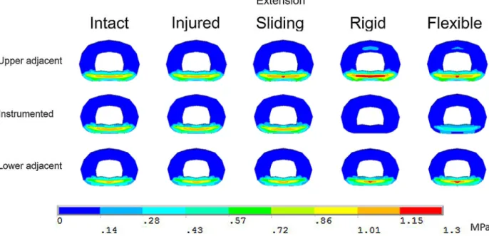
Similar trends were found in flexion, extension and lateral bending. Peak values in the instrumented level increased with a higher interpedicular displacement, while the opposite tendency was found for adjacent levels. Results for extension loading are presented as example (Fig. 6).
In axial rotation, sliding and rigid implants increased Von Mises stress in inferior adjacent level (peak: 1.33 MPa), while the stress in adjacent levels with the flexible rod was comparable to the injured configuration (peak: 0.89 MPa).
4. Discussion
From a clinical point of view, various types of posterior dynamic instrumentations may be considered for different indications in the lumbar spine. This type of devices is intended to reduce the risk of adjacent segment degeneration. However, their clinical signif-icance remains controversial, as the long-term effect on adjacent lumbar segments has not been proven clinically to date[4]. Fur-thermore, the implant’s design and capacity to restore segmental lordosis appear crucial, as a lack of lordosis within the instru-mented segments might induce a compensatory risk of adjacent hyper-lordosis and thus increase the risk for facet joint deteriora-tion[22]. These different designs can yield different ID, which could be related with loosening issues. This work used a spinal finite ele-ment (FE) model with the aim of understanding the relationship between a kinematic parameter that varies with the implant design, the ID, and the internal loads on implants and intervertebral discs. As any spinal FE model, there are limitations since muscles and gravitational loads are not represented. Moreover, it is difficult to validate all the results, particularly when considering internal
Fig. 3. ID for different configurations.
Fig. 4. Relationship between ID and maximum shear forces in screws. R-rigid implant; F-flexible implant; S-sliding implants with different frictions coefficients (S1 to S7).
Fig. 6. Von Mises stress of the intervertebral disc in extension loading. Results are presented as an axial middle cut in the intervertebral disc.
forces or stresses. However, the global consistency of the model was checked using in vitro data, in which the mobility curve of the model was compared with an experimental corridor in differ-ent configurations. The model is within the experimdiffer-ental corridors except for the initial part of the curve, in the configuration without facets. Even in this case, the difference is lower than 0.5◦.
Validating finite element models of intervertebral discs in rela-tion to the stress distriburela-tion in models is not an easy task because it would require pressure measurements which distribution could be variable within the disc space. This limitation, which is inher-ent to such numerical studies, should be kept in mind. However, FE models present the advantage of having their geometry and material properties controllable, in such they are useful for com-parative biomechanical studies, with the aim to clarify the main factors related to instrumented spine biomechanics.
Different conceptual implants resulted in different IDs that were compared to normal and shear forces in pedicle screws. Normal force relates to classic pullout tests, which are widely used to evalu-ate the strength of screw-bone assembly[23,24]. Even though those tests are used to evaluate the grip of a screw, screw loosening could also be related to shear forces between screw and bone interface. Shear forces might progressively loosen the bone around the screw during daily physical activities[25]. This phenomenon of toggle migration could drastically decrease the pullout strength, weak-ening the desired fixation[26]. The results in the present study showed that when an implant design allows ID, shear forces are reduced in the screws.
Implant design and associated IDs showed to be also related with intervertebral disc Von Mises stress. In the present study, it was demonstrated that allowing ID would decrease stress in adjacent discs, whereas limiting ID would decrease stress at the instrumented segment. These considerations are clinically relevant when deciding on the amount of stabilization required at the instru-mented level versus risk of adjacent segment degeneration and screw loosening.
Yeager et al.[27]compared the ID of different implants using in vitro experiments. In their results, no significantly differences was observed between the IDs of rigid and flexible designs for flexion-extension. Even if the protocols are not strictly comparable, comparing their results with ours, the ID found with the FE model-ing was in the experimental range for intact, lesion and with flexible implants. A difference was found when comparing IDs for the rigid
implant configuration (FE model = 0; in vitro = 2.44± 1.15 mm). The higher in vitro ID could be related to a sliding between the screw and rod, which were not taken into account in our modeling of rigid implant. Further experimental studies on ID with thorough observation of local phenomenon could help understanding this issue.
Nevertheless, to our knowledge, this is the first work that obtains the ID in finite element modeling and the result highlights the relation of limiting ID and stresses in screws or intervertebral discs. ID can be an important factor to be taken into account in future implant designs, when screw loosening issues are concern-ing. In clinical practice, with a given implant, ID may be variable among individuals and with time. Future studies considering in vivo ID measurements could help to understand possible changes in ID related to clinical outcome.
Disclosure of interest
L.V.P.C.L., P.R. and W.S. declare that they have no competing interest.
The author Y.P.C. has received payment in the last 36 months from implant companies for different activities. These activities consisted in royalties, consulting, speaking and teaching arrange-ments. They were outside the submitted work. The companies involved were Clariance, Stryker, Medtronic, LDR Medical and Cer-aver.
Acknowledgements
CNPq Brazil for supporting PhD studies of Lucas VPC Lima. Paris Tech Biomec AM chair program on subject-specific musculoskele-tal modeling for funding (with the support of COVEA and Société Générale).
References
[1]Levin DA, Hale JJ, Bendo JA. Adjacent segment degeneration following spinal fusion for degenerative disc disease. Bull NYU Hosp Jt Dis 2007;65:29–36.
[2]Serhan H, Mhatre D, Defossez H, Bono CM. Motion-preserving technologies for degenerative lumbar spine: the past, present and future horizons. SAS J 2011;5:75–89.
[3]Charles YP, Persohn S, Steib JP, Mazel C, Skalli W. Influence of an auxiliary facet system on lumbar spine biomechanics. Spine (Phila Pa 1976) 2011;36:690–9.
[4]Prud’homme M, Barrios C, Rouch P, Charles YP, Steib JP, Skalli W. Clinical outcomes and complications after pedicle-anchored dynamic or hybrid lum-bar spine stabilization: a systematic literature review. J Spinal Disord Tech 2015;28:E439–48.
[5]Yerby S, Ehteshami J, McLain R. Loading of pedicle screws within the vertebra. J Biomech 1997;30:951–4.
[6]Meyers K, Tauber M, Sudin Y, Fleischer S, Arnin U, Girardi F, et al. Use of instrumented pedicle screws to evaluate load sharing in posterior dynamic stabilization systems. Spine J 2008;8:926–32.
[7]Freeman AL, Fahim MS, Bechtold JE. Validation of an improved method to cal-culate the orientation and magnitude of pedicle screw bending moments. J Biomech Eng 2012;134:104502.
[8]Cook DJ, Yeager MS, Cheng BC. Interpedicular travel in the evaluation of spinal implants: an application in posterior dynamic stabilization. Spine (Phila Pa 1976) 2012;37:923–31.
[9]Champain S, Benchikh K, Nogier A, Mazel C, Guise JD, Skalli W. Validation of new clinical quantitative analysis software applicable in spine orthopaedic studies. Eur Spine J 2006;15:982–91.
[10]Chen SH, Zhong ZC, Chen CS, Chen WJ, Hung C. Biomechanical comparison between lumbar disc arthroplasty and fusion. Med Eng Phys 2009;31:244–53.
[11]Sjovold SG, Zhu Q, Bowden A, Larson CR, de Bakker PM, Villarraga ML, et al. Biomechanical evaluation of the Total Facet Arthroplasty System®(TFAS®): loading as compared to a rigid posterior instrumentation system. Eur Spine J 2012;21:1660–73.
[12]Gornet MF, Chan FW, Coleman JC, Murrell B, Nockels RP, Taylor BA, et al. Biome-chanical assessment of a PEEK rod system for semi-rigid fixation of lumbar fusion constructs. J Biomech Eng 2011;133:081009.
[13]Rohlmann A, Zander T, Bergmann G, Boustani HN. Optimal stiffness of a pedicle-screw-based motion preservation implant for the lumbar spine. Eur Spine J 2012;21:666–73.
[14]Wilke HJ, Heuer F, Schmidt H. Prospective design delineation and subsequent in vitro evaluation of a new posterior dynamic stabilization system. Spine (Phila Pa 1976) 2009;34:255–61.
[15]Bellini CM, Galbusera F, Raimondi MT, Mineo GV, Brayda-Bruno M. Biome-chanics of the lumbar spine after dynamic stabilization. J Spinal Disord Tech 2007;20:423–9.
[16]Charles YP, Lima LVPC, Persohn S, Rouch P, Steib JP, Skalli W. Influence of an auxiliary facet system on intervertebral discs and adjacent facet joints. Spine J 2013;13:1293–300.
[17]Lafage V, Gangnet N, Sénégas J, Lavaste F, Skalli W. New interspinous implant evaluation using an in vitro biomechanical study combined with a finite-element analysis. Spine (Phila Pa 1976) 2007;32:1706–13.
[18]Lavaste F, Skalli W, Robin S, Roy-Camille R, Mazel C. Three-dimensional geometrical and mechanical modelling of the lumbar spine. J Biomech 1992;25:1153–64.
[19]Huec JCL, Lafage V, Bonnet X, Lavaste F, Josse L, Liu M, et al. Validated finite element analysis of the maverick total disc prosthesis. J Spinal Disord Tech 2010;23:249–57.
[20]Rohlmann A, Burra NK, Zander T, Bergmann G. Comparison of the effects of bilateral posterior dynamic and rigid fixation devices on the loads in the lumbar spine: a finite element analysis. Eur Spine J 2007;16:1223–31.
[21]Renner SM, Natarajan RN, Patwardhan AG, Havey RM, Voronov LI, Guo BY, et al. Novel model to analyze the effect of a large compressive follower pre-load on range of motions in a lumbar spine. J Biomech 2007;40:1326–32.
[22]Chen H, Charles YP, Bogorin I, Steib JP. Influence of 2 different dynamic sta-bilization systems on sagittal spinopelvic alignment. J Spinal Disord Tech 2011;24:37–43.
[23]Brasiliense LBC, Lazaro BCR, Reyes PM, Newcomb AGUS, Turner JL, Crandall DG, et al. Characteristics of immediate and fatigue strength of a dual-threaded pedicle screw in cadaveric spines. Spine J 2013;13:947–56.
[24]Zhang QH, Tan SH, Chou SM. Investigation of fixation screw pullout strength on human spine. J Biomech 2004;37:479–85.
[25]Choma TJ, Frevert WF, Carson WL, Waters NP, Pfeiffer FM. Biomechanical analysis of pedicle screws in osteoporotic bone with bioactive cement aug-mentation using simulated in vivo multicomponent loading. Spine (Phila Pa 1976) 2011;36:454–62.
[26]Law M, Tencer AF, Anderson PA. Caudo-cephalad loading of pedicle screws: mechanisms of loosening and methods of augmentation. Spine (Phila Pa 1976) 1993;18:2438–43.
[27]Yeager MS, Cook DJ, Cheng BC. In vitro comparison of dynesys, PEEK and tita-nium constructs in the lumbar spine. Adv Orthop 2015;2015:895931.
[28]Goel VK, Monroe BT, Gilbertson LG, Brinckmann P. Interlaminar shear stresses and laminae separation in a disc. Finite element analysis of the L3-L4 motion segment subjected to axial compressive loads. Spine (Phila Pa 1976) 1995;20:689–98.
[29]Skaggs DL, Weidenbaum M, Iatridis JC, Ratcliffe A, Mow VC. Regional variation in tensile properties and biochemical composition of the human lumbar anulus fibrosus. Spine (Phila Pa 1976) 1994;19:1310–9.