is an open access repository that collects the work of Arts et Métiers Institute of Technology researchers and makes it freely available over the web where possible.
This is an author-deposited version published in: https://sam.ensam.eu
Handle ID: .http://hdl.handle.net/10985/7356
To cite this version :
Armaghan KHAN, Thanh Hung NGUYEN, Christophe GIRAUD-AUDINE, Gabriel ABBA, Régis BIGOT, Betty LEMAIRE-SEMAIL - Progressive wave: a new multisource vibration technique to assist forming processes - kinematic study, simulation results and design proposition - 2013
Progressive wave: a new multisource vibration technique
to assist forming processes - kinematic study, simulation
results and design proposition
A. Khana, T. H. Nguyena, C. Giraud-Audine a, G. Abba b, R. Bigot a, B. Lemaire-Semail c
a. ´Ecole Nationale Sup´erieure d’Arts et M´etiers b. ´Ecole Nationale d’Ing´enieurs de Metz
c. Universit´e de Lille 1
Abstract :
Use of vibration in the forming process has already shown numerous advantages in the improvement of mechanical and surface properties of workpiece such as good surface or less friction between die and workpiece. The aim of this work is to develop a mathematical model of a progressive wave in the lower die due to the vibration given by multi piezoelectric actuators to assist the forging process. Based on the mathematical model, simulations using finite element software Forge2011 have been performedR
to observe the presence of progressive wave in the workpiece due to the movement of the lower die. The simulations’ results confirm the existence of progressive wave in the workpiece and demonstrate the effect of progressive wave to reduce the forging load and improve the forging process.
Mots clefs :
Modeling, progressive wave, forging process1
Introduction
The two traditional techniques to improve the forming process are using lubricants and preheating the material. The major benefits of using lubricants are reduction of forging load, tools’ wear and improved surface finish (surface effect ). The main limitation in using lubricants is the incompatibility with environment and its chemical reaction with tool/workpiece material. With the preheating method, the material’s ductility increases while yield strength decreases (volume effect ) but it affects important material properties such as surface structure, crystallographic structure and material strength as during heating there are voids, composition, and inclusion or precipitation formation. Application of vibration is the most recent and beneficial technique to improve the forming processes because it offers both surface and volume effects [1]. Moreover, it can prevent the undesirable effects related to two preceding techniques.
Until now, most of research in vibration assisted forming process concentrates on applying translational vibrations in axial and radial direction [2, 3, 4, 5, 6, 7, 8]. Some studies have been performed in the domain of orbital forging combined with translation [9, 10]. However, application of vibration in both translation and rotation to produce progressive wave during the forming process has never been discussed before. In this article, we will adopt this strategy to the metal forging process. The work will be presented in two parts. The first part is the kinematic study and mathematical modeling of progressive wave by using multi vibration sources. The second part concentrates on finite element simulations performed in software Forge2011 to see the impact of using progressive wave in theR
forging process and its affect on forging load’s reduction. Finally, discussion on obtained results and perspective of experimental verification will be outlined in the last section of this paper.
2
Kinematic modeling of progressive wave on the lower die’s
move-ment
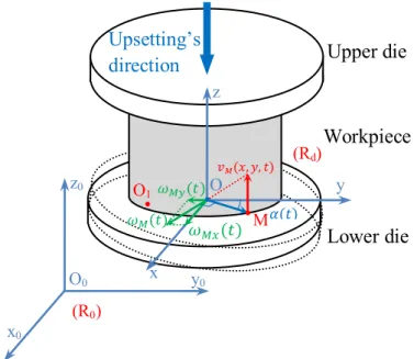
To establish a mathematical model of progressive wave on the lower die, the movement of two points in this die will be analyzed. Two Cartesian frames are used in this study: R0 is the one attached
to the fixed base and Rd is the other attached to the lower die. In the Rd frame, a point M with
coordinate (x, y, 0) and O1 with coordinate (x1, y1, 0) are considered for kinematic study (Figure 1).
A cylindrical workpiece is put in contact with two die’s surfaces and its symmetrical axis is on the Oz
axis.
Figure 1: Kinematic scheme of the lower die in the forging process
If the movement of lower die is defined by two rotations (around x and y axes) and one translation (in z-direction). The rotation of the lower die expressed in the fixed base R0 can be presented by the
following matrix: Rx.Ry = 1 0 0 0 1 −θx 0 θx 1 . 1 0 θy 0 1 0 −θy 0 1 = 1 0 θy θxθy 1 −θx −θy θx 1 (1)
with Rx, Ry are the matrix of rotation around x and y axes with the small angle of rotation θx and θy.
The position of points M and O can be defined in R0:
O0M(R0)= x y −xθy+ yθx+ z O0O1(R0) = x1 y1 −x1θy+ y1θx+ z (2)
Now, if the movement at point O1 is imposed as:
−x1θy+ y1θx+ z = za(t) (3)
Then the movement of point M can be obtained as follows:
O0M(R0)= x y −(x − x1)θy+ (y − y1)θx+ za(t) (4)
If we assigned: x − x1 = Rcosψ and y − y1= Rsinψ, then we can have:
zM(t) = −Rcosψθy+ Rsinψθx+ za(t) (5)
We are therefore capable of choosing a sinusoidal progressive wave for the cylinder of radius R and superposing a movement in z-direction defined by za(t).
If we are only interested in the generation of progressive wave, then ∆z(t) = −Rcosψθy+ Rsinψθx
depends only to the radius R of workpiece and the amplitudes of rotation angles. In the case of having an error in workpiece’s centering in the lower die, a movement in z-direction is imposed on the workpiece in such way z(t) = R1cosψ1θy− R1sinψ1θx with maximum amplitude R1θmax.
In the other hand, if we want to achieve the sufficient amplitude at one point on the die to keep the workpiece on the die and to obtain the maximum velocity of deformation V0, it is only important to
consider the velocity at point M on the die. The lower die’s radius determines the amplitudes of the movement around rotations’ axes and the movement along z.
In this paper, only the progressive wave created by two rotations around two axes Ox and Oy will be
studied. Consider the movement of a point M at the lower surface of the workpiece in a distance R from the center O. At time t, the position of point M in the coordinate Oxy is defined by an angle α
between Ox and OM.
The tangential velocity at point M is defined by −→vM and is calculated as:
− →v
M(x, y, t) = −→ωM(t) ×
−−→
OM (6)
The constant angular velocity vector −→ωM is projected on the two axis Ox and Oy and is given by :
ωM x(t) = Ω0cos α
ωM y(t) = Ω0sin α
(7)
with Ω0 is the maximum amplitude of angular velocity and α = ωt, where ω is the angular velocity of
vector −→ωM around Oz.
The angular displacement θx and θy can be calculated by the following equations:
θx(t) = Z t 0 ωM x(t) = θx0+ Ω0 ω sin(ωt) θy(t) = Z t 0 ωM y(t) = θy0− Ω0 ω cos(ωt) (8)
where θx0 and θy0 are the initial angles of rotation.
The upper die is supposed to move down at a constant velocity V0. The instantaneous height reduction
due to these dies’ movement can be written as follows: h(t) = h0− V0t − Rθ(t) = h0− V0t − R
Z t
0
Ω0sin(ωt + φ)dt (9)
where h0 is the initial height of workpiece and θ(t) =
Rt
0Ω0sin(ωt + φ)dt is the angle de rotation due
to the angular velocity vector −→ωM at the point M at the moment t with the initial angle φ.
Height reduction rate at point M can be written:
˙h(t) = −V0t − RΩ0sin(ωt + φ) (10)
From equation (10), we can obtain ˙hmax = −V0t + RΩ0. If ˙hmax > 0, the contact between the
workpiece and dies is lost, therefore, the maximum value of ˙hmax is 0 . In that case, the maximum
amplitude of the rotation depends on the defined velocity V0 and the radius of the workpiece:
Ω0max =
V0
3
Finite element simulation for forging process with multisource
vibrations
Finite element simulations have been performed in viscoplastic domain for forging processes with and without vibrations in FORGE2011 . Since this paper focuses on a viscoplastic material, the materialR
behavior can be expressed by Norton-Hoff constitutive law (extracted from Hansel and Spittel rheology law), according to which:
σ0 = k εnε˙m (12)
From the equation (12), it can be seen that the flow stress σ0 depends on the equivalent deformation
ε, the equivalent deformation rate ˙ε along with the coefficients of material (the consistency k, the hardening coefficient n and the sensitivity to strain rate m). Because this study is about cold forging process, the temperature terms are not included in this model. Friction is taken into account by using a Coulomb limited Tresca model in this case.
The input data for this simulation is the two angular velocities generated by the equations (7) and transferred to software FORGE2011 with the help of generic press for further use during the forgingR
process. Figure 2 presents the FORGE model, showing the three main parts of the forging process (upper die, workpiece and lower die). Table 1 summarizes the different parameters of model and process used in these simulations.
F
Lower die with
generic press
Workpiece
Upper die
X Y Z (0 0 0) (0 0 -40)Figure 2: FORGE2011 model for FEM simulationsR
Table 1: FEM model parameters used forging process simulations
Parameters Values
Workpiece material coefficient (Aluminum) K = 161.9; n = 0.2; m = 0.1 Friction coefficients µ = 0.05, m = 0.8 Workpiece geometry R = 20mm; h0 = 40mm
Workpiece final height hf = 15mm
Upper die velocity V0= −3mm/s
Progressive wave frequency f = 10Hz Rotation velocity Ω0= Ω0max = 0.15rad/sec
The simulation starts at time t=0, then the initial angular displacements θx0, θy0 are calculated from
the equation (8) as follows:
θx(0) = 0; θy(0) = 0; ⇒ θx0= 0; θy0 = Ω0 2πf = V0 2πf R = −0.00239rad = −0.137 ◦
Presence of rotation in the lower die can be found out by measuring displacement for small period of time. Similarly, the presence of rotation on the lower surface of workpiece can be measured with the help of a-priori sensors. These sensors can also be used to find out other important data measurement such as total strain, strain rate, displacement and velocities in x, y and z directions.
Once the presence of rotation at the upper surface of lower die and in the lower surface of workpiece has been verified, the effect of the multi vibration on the forging process can be observed. This can be done by comparing the forging load required for the processes with and without multi vibration.
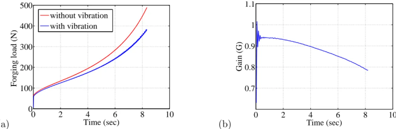
This comparison has been presented in Figure 3. Figure 3(a) presents load required for the forging processes with and without vibration. It shows that there is forging load reduction when multi vibrations have been applied.
(a) 0 2 4 6 8 10 0 100 200 300 400 500 Time (sec) Forging load (N) without vibration with vibration (b) 0 2 4 6 8 10 0.7 0.8 0.9 1 1.1 Time (sec) Gain (G)
Figure 3: (a) Load verses time for forging processes with and without multi vibration (b) Gain in forging load reduction : f=10Hz and Ω0max = 0.15rad/sec.
Normalized load reduction can be found out by normalizing the forging load over the time. Normalized load reduction or gain in forging load reduction is presented in Figure 3b. Forging load reduction of 21.5% has been obtained at the end of the process. It can be seen that initially gain in forging load reduction is small but with time, this gain has increased as plastic deformation increases. This phenomenon shows the advantage of using progressive wave in the forging process.
On Figure 4, the velocity field has been plotted for two time instants during the time period T = 0.1s (t=2 − 2.1s). It can be clearly seen that there is change in the velocity vector’s direction from the right side of workpiece in the figure 4(a) to the left side of workpiece in the figure 4(b) during a half period of the progressive wave. This explains the reduction of the stress in the material and the reduction of the friction on the lower die.
(a) t=2.025sec (b) t=2.075sec Figure 4: Velocity field of workpiece (a) t = T4 (b) t = 3T4
4
Conclusions and future work
In this work, generation of progressive wave is predicted with the help of multiple vibration sources during the forging process. The kinematic study has been presented and applied during the forging process simulation performed in the Forge2011 . Simulation’s results confirm the gain in forging loadR
reduction. Idea of applying multi-vibration sources to generate progressive wave during the forging process has been discussed for the first time and an experimental approach to employ it is needed.
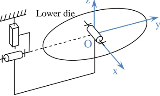
In the future work, a comparison with experimental reduction in forging processes is needed to confirm these simulation results. A mechanical system must be designed with the strict conditions to support the forging load (up to 10 kN) and generate the displacements (in order of µm) to perform a proposed progressive wave of movement in the lower die. A kinematic scheme of mechanical system is presented in Fig. 5. However, the use of elastic guiding in place of the conventional guiding must be considered to prevent the mechanical backlash which is incompatible with the very small required displacements.
Lower die
x
O
z
y
Figure 5: Kinematic scheme of mechanical system
The piezoelectric actuators, which are widely used for this kind of application [2], are promising sources of vibrations to meet these requirements. However, a methodology for designing and controlling mechanical system integrating multi piezoelectric actuators must be studied further to realize the proposed kinematic movement.
References
[1] Presz, W 2007 Flexible Manufacturing System For Vibration Assisted Microforming 10th Esaform Conference on Material Forming pp. 677-684, Zaragoza, Spain
[2] Ly, R., Giraud-Audine, C., Abba, G., Bigot, R. 2009 Experimentally validated approach for the simulation of the forging process using mechanical vibration International Journal of Material Form-ing 2(1) pp. 133-136
[3] Armaghan, K. , Giraud-Audine, C., Abba , G., Bigot, R. 2011 Effects of Vibration on metal forming process: Analytical approach and finite element simulations AIP conference proceedings 1315 pp. 787-792
[4] Lucas, M. , Huang, Z. , Adams, M. J. 2000 Modeling wall boundary conditions in an elasto-viscoplastic material forming process Journal of Materials Processing Technology 107 pp. 267-275 [5] Hung, J.C. , Tsai, Y.C. , Hung, C. 2009 Frictional e?ect of ultrasonic-vibration on upsetting
Ultrasonics 46 pp. 277-284
[6] Daud, Y. , Lucas, M. , Huang, Z. 2006 Superimposed ultrasonic oscillations in compression tests of aluminium Ultrasonics 44 pp. 511-515
[7] Daud, Y. , Lucas, M. , Huang, Z. 2007 Modelling the effects of superimposed ultrasonic vibrations on tension and compression tests of aluminium Journal of Materials Processing Technology 186 pp. 179-190
[8] Aziz, S.A. , Lucas, M. 2010 The Effect of Ultrasonic Excitation in Metal Forming Tests Applied Mechanics and Materials 24-25 pp. 311-316
[9] Zhi-hong, J. , Gai-pin,C. 2010 Volume effect preparatory research of vibrational rotary forging Proc. Mechanic Automation and Control Engineering (MACE) 24-25 pp. 5621-5625
[10] Zhi-hong, J. , Gai-pin,C. 2011 Surface effect preparatory research of vibrational rotary forging Advanced Materials Research 154-155 pp. 1513-1517