Science Arts & Métiers (SAM)
is an open access repository that collects the work of Arts et Métiers Institute of Technology researchers and makes it freely available over the web where possible.
This is an author-deposited version published in: https://sam.ensam.eu
Handle ID: .http://hdl.handle.net/10985/9128
To cite this version :
Guochao GU, Raphaël PESCI, Eric BECKER, Laurent LANGLOIS, Régis BIGOT - In Situ
Microstructure Observation Of Steel Grades In The Semi-Solid State For Thixoforging Process By Using Confoncal Laser Scanning Microscopy Solid State Phenomena Vol. 217218, p.1522 -2015
Any correspondence concerning this service should be sent to the repository Administrator : archiveouverte@ensam.eu
Science Arts & Métiers (SAM)
is an open access repository that collects the work of Arts et Métiers ParisTech researchers and makes it freely available over the web where possible.
This is an author-deposited version published in: http://sam.ensam.eu
Handle ID: .http://hdl.handle.net/null
To cite this version :
Guochao GU, Raphaël PESCI, Eric BECKER, Laurent LANGLOIS, Régis BIGOT - In Situ
Microstructure Observation Of Steel Grades In The Semi-Solid State For Thixoforging Process By Using Confoncal Laser Scanning Microscopy Solid State Phenomena Vol. 217218, p.1522 -2015
Any correspondence concerning this service should be sent to the repository Administrator : archiveouverte@ensam.eu
In Situ Microstructure Observation Of Steel Grades In The Semi-Solid
State For Thixoforging Process By Using Confoncal Laser Scanning
Microscopy
Guochao Gu
1, a, Raphaël Pesci
2,b, Eric Becker
1,c, Laurent Langlois
1,d,
and Régis Bigot
1,e1
Laboratoire Conception Fabrication Commande (EA-4495), Arts et Métiers ParisTech Metz, France
2
Laboratoire d’Etude des Microstructures et de Mécanique des Matériaux (LEM3), UMR CNRS 7239, Arts et Métiers ParisTech CER Metz
Metz, France
a
guochao.gu@gmail.com, braphael.pesci@ensam.eu, ceric.becker@ensam.eu,
d
laurent.langlois@ensam;eu, eregis.bigot@ensam.eu
Keywords: steel grades; semi-solid; microstructure evolution; CLSM
Abstract. The microstructure plays a crucial role for steel semi-solid forming process, and
particularly for the steel thixoforging process, since it determines the thixotropic flow behavior of materials in the semi-solid state. Therefore, it is necessary to well understand the microstructure evolution during high speed heating and forming. Classically, it is investigated on a solid material quenched from semi-solid state by 2D characterization techniques. However, the semi-solid microstructure could probably not be preserved in the solid state by quenching due to complicated phase transformations or high diffusion rate of alloying elements during cooling, especially at low liquid fractions. In order to avoid this, a new in situ technique - high temperature Confocal Laser Scanning Microscopy (CLSM) - was developed and used for studying the microstructure evolution directly at high temperature.
The present study aims at providing an experimental investigation of the microstructure evolution on several steel grades (M2, 100Cr6 and C38LTT) during heating from the as-received state to the semi-solid state (heating rate: ~200°C/min) and finally cooled to the solid state (cooling rate: ~200°C/min).
It has been found that the temperature sensitivity of liquid fraction (∆T/ ∆fl) of these grades is much different. In addition, during cooling, there is a significant difference in diffusion rate of alloying elements between these grades. In M2, thanks to the high content of alloying elements and their low diffusion rate, the semi-solid temperature range is greater and its microstructure in the semi-solid state could be preserved by quenching process or even at a low cooling rate. On the contrary, the microstructure of other steel grades 100Cr6 and C38LTT in semi-solid state can only be revealed by CLSM at high temperature, because of the lower volume fraction of alloying elements and their high diffusion rate. It is very interesting to use high temperature CLSM to in situ investigate the microstructure evolution in the semi-solid state, especially at low liquid fraction. Since the microstructure of M2 in the semi-solid state can be reserved after cooling, it is possible to identify liquid area by the post-mortem examination. Therefore, the material flow behavior of thixoforged parts could be investigated.
Introduction
Taking advantage of the thixotropic properties, the metal slurries can be processed to produce complex parts with good mechanical properties by semi-solid forming. The thixotropic behavior is determined by the non-dendritic microstructure which consists of spheroidal grains in a liquid matrix. [1] Thixoforming is one of semi-solid forming route, in which a billet is heated until reaches the
required semi-solid state with proper microstructure and then formed in the die. This technology has been applied in alloys with low melting temperature, such as magnesium and aluminum alloys [2]. Several collaborative activates on thixoforming were performed worldwide. The extensive effort was mainly concentrated on the industrialization of the steel thixoforming process to overcome the major obstacles. However, in these projects, the interested liquid fraction range was (0.3 < fl< 0.6) [3]. In our study, we are interested in low liquid fractions (0.1 < fl < 0.3).
The required microstructure for semi-solid forming process can be obtained by several routes, which have been summarized in Ref. [4]. The recrystallization and partial melting (RAP) [5] and strain-induced melt-activated (SIMA) [6] are the more established solid state feedstock preparation routes. Recently, it was shown that tool steel X210CrW12 and M2 [7], stainless steel with a peritectic reaction [8], 100Cr6 [9] and C38 [10] could be subjected to a direct partial re-melting route, from their as-received conditions, to obtain a thixoformable microstructure. The volume fraction of solid phase and its distribution are important microstructure parameters that remain to be investigated, especially at low liquid fractions, because they crucially influence the rheological behavior [11] and therefore the flow behavior of a material during its forming [12]. Due to the high diffusion rate of elements and phase transformation behavior of steel during quenching, it is difficult to characterize the microstructure at low liquid fractions by conventional 2D quantitative metallography on quenched samples.
In situ techniques, such as synchrotron X-ray microtomography [13], Environmental Scanning Electron Microscopy (ESEM) [14] and Confocal Laser Scanning Microscope (CLSM) [15] have been developed and employed for real-time microstructure investigations.
In this study, C38LTT (low temperature for thixoforging), 100Cr6 and M2, were investigated considering the industrial applications and suitability of the thixoforging process, in particular to study the microstructure evolution during heating from the solid state to the semi-solid state by using in situ (CLSM) and ex situ techniques. In addition, a 3D semi-solid microstructure was reconstructed to show the solid skeleton and its distribution.
Experimental procedure
Materials. The materials used in this work were C38LTT, bearing steel 100Cr6 and high speed
tool steel M2. C38LTT was specially manufactured for the thixoforming process by ASCOMETAL. The 100Cr6 was supplied after hot rolling process. After experiencing the hot rolling at a temperature of ~1100 °C, quenching and subsequently three times annealing for 1 h at 540 °C, the M2 was received from the supplier ThyssenKrupp. The chemical composition of the starting materials is given in Table 1. C38LTT and 100Cr6 were investigated for the reason of industrial applications, while M2 was chosen for its high content of alloying elements for 3D characterizations.
Table 1. Chemical composition of the steel grades. Chemical composition (wt 10-3%)
C Si Mn S P Ni Cr Mo Cu Al Sn As B* V Ti Nb Ca* N* W
C38LTT 399 596 1424 83 77 91 130 29 114 3 9 9 4 89 15 0 10 0 100Cr6 988 230 326 6 7 210 1428 82 194 31 13 10 2 4 3 1 2 109 0
M2 850 35 250 ≤40 ≤40 200 4100 5000 100 1900 6400
Differential Scanning Calorimetry (DSC) measurements. DSC analyses were performed to
estimate solidus and liquidus temperatures and the liquid fraction as a function of temperature of these materials. The measurement was performed in ASCOMETAL CREAS [12] for the C38LTT and 100Cr6 with heating rate of 20°C/min. M2 was tested by using a NETZSCH 404C Pegasus® at the heating rate of 20°C/min. Samples (Ø3mm * 1.5mm) were machined from several billets in various positions in order to minimize the possibility of getting non-representative results due to possible variations of local composition caused by the segregation in longitudinal direction. Alumina with the same weight as the sample was used as a reference and Argon was applied during heating in order to prevent oxidation.
In situ microstructure observation by Confocal Laser Scanning Microscopy (CLSM). A
LasertecTM 1LM21H-SVF17SP CLSM combined with a heating stage was used to perform the in situ investigations of microstructure evolution at high temperature. The sample (Ø5 * 3mm) was heated in a high purity argon atmosphere. In addition, titanium foils were placed near the sample surface to consume the oxygen during heating. Thus the oxidation phenomenon could be avoided. During the real-time investigations, various material samples experienced similar heating route but different maximum temperature according to the DSC results: 1450°C for C38LTT, 1400°C for 100Cr6 and 1340°C for M2. The sample was heated at a rate of 50°C/min from room temperature to 300°C with a 50s holding time at 300°C; and then at 200°C/min to the maximum temperature without holding time. It was then cooled at 200°C/min to room temperature. The heating stage was calibrated, showing that temperature difference between the reading temperature and the real temperature did not exceed ±15°C. Before the investigations, all samples were polished down to 1µm and etched to reveal the microstructure as well as adjust the focus and the magnification of the CLSM. After in situ ivestigations, the samples were prepared and observed at room temperature by optical microscopes and Scanning Electron Microscope (SEM).
Image analyses. In order to study the microstructure in the semi-solid state, billets with a diameter
of 38mm was partially induction heated. After quenching, the billets were subsequently ground, polished and etched using Nital 2% to reveal their microstructures. Microstructure observation and analysis were conducted by using an optical microscope and a JEOL 7001FLV SEM equipped with an EDS system. In addition, a 3D microstructure was constructed to show the solid skeleton and the liquid distribution.
Results and discussions
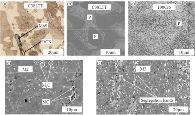
Fig. 1. Micrographs of as-received samples. C38LTT in (a) longitudinal direction (optical) and (b) transversal direction (SEM); 100Cr6 in (c) transversal direction; M2 in (d) transversal direction (SEM) and (e) longitudinal
direction (SEM). P: pearlite; F: ferrite.
Starting materials. As shown in Fig. 1, the microstructure on transversal and longitudinal
sections of materials were obtained by optical microscope and SEM. In addition, the inclusions of the materials were identified by EDS analyses. The results showed that the ferritic pearlitic steel C38LTT contained MnS and TiCN inclusions (Fig. 1a); 100Cr6 steel showed a pearlitic microstructure (Fig. 1c). As for the as-received M2 steel, the SEM-EDS observation found whiter carbides (M6C-type
carbides which are rich in tungsten and molybdenum) and darker ones (MC-type carbides which are rich in vanadium, tungsten and molybdenum) (Fig. 1d and e). Moreover, the segregation banding along the longitudinal direction of the materials were also observed, which is related to the rolling process during manufacturing route. By using mean lineal intercept image analyses method, the average grain size of the materials is similar ~10µm.
Liquid fraction curve. Liquid fraction curves as a function of temperature obtained from DSC
tests for the steel grades are shown in Fig. 2. It can be observed from these curves that the special manufactured C38LTT has a narrow semi-solid interval (~100°C) for the heating rate of 20°C/min, while M2 and 100Cr6 show larger semi-solid intervals (~190°C and 160°C, respectively). Additionally, the solidus temperature varies with alloying elements contents: ~1410°C for C38LTT, 1330°C for 100Cr6 and ~1250°C for M2. Moreover, the liquid fraction curve of M2 exhibits the complex melting behavior of M2 which may be caused by the dissolution of the carbides (MC and M6C). Considering the DSC results, the materials (C38LTT, 100Cr6 and M2) were investigated in the
liquid fraction range between 10% and 30%, which corresponds to the temperature interval of (~1420°C – ~1460°C) for C38LTT, (~1370°C – ~1400°C) for 100Cr6 and (~1250°C – ~134°C).
Fig. 2. Liquid fraction as a function of temperature obtained by DSC (20°C/min).
Metallography and image analyses. In order to study the microstructure evolution during
heating, the materials were investigated by quenching experiments and in situ CLSM tests.
Quenching experiments were carried out on the steel grades at their temperature ranges. Fig. 3
shows the microstructure of the steel grades quenched from the semi-solid state. For C38LTT and 100Cr6, martensitic structure was observed with barely evidence of former liquid phase after quenching (Fig. 3 a and b). It is thought that the diffusion rate of the alloying elements during quenching was very fast that the cooling rate could not preserve the microstructure in the semi-solid state. As a result, the former liquid zones can not be identified from the microstructure quenched from the semi-solid state to room temperature. In comparison, the structures with spheroidal grains surrounded by interconnected carbides were observed for M2 (Fig. 3 c). The new carbides was formed from the liquid phase since the liquid was rich in alloying elements at high temperature.
Fig. 3. Microstructure of steel grades quenched from semi-solid state. 18
In situ CLSM observations were first performed on C38LTT and 100Cr6 in order to study their
microstructures at high temperature because it was difficult to retrieve their microstructures in the semi-solid state by the conventional quenching experiments. The microstructure evolution of M2 was also real-time observed by CLSM.
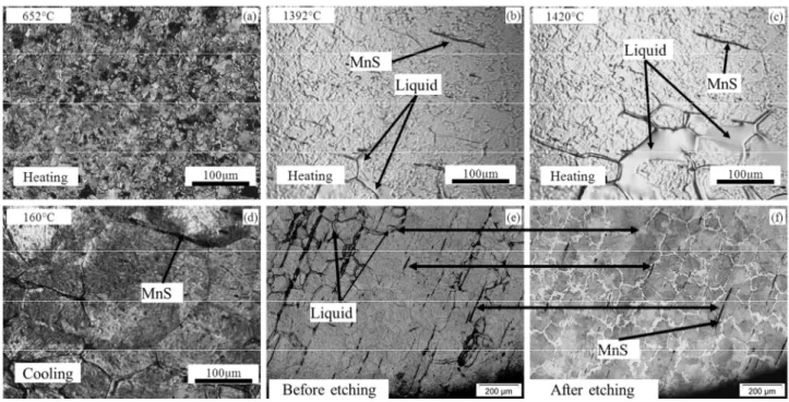
CLSM Micrographs of C38LTT at different temperatures were presented in Fig. 4. As shown in Fig. 4, the microstructure of C38LTT remained the ferritic and perlitic with the presence of small inclusions (Fig.4 (a)) until ~740°C, at which the austenization transformation occurred - the ferrite and perlite transformed to austenite. When entering the semi-solid zone, the liquid films appeared at the grain boundaries and the MnS inclusions were still remaining in the matrix and along the grain boundaries (Fig. 4 (b)). The liquid content increased with temperature. However, the liquid phase distribution was not uniform, as shown in Fig. 4 (c). The MnS inclusions changed a little even at higher temperature (Fig. 4 (c)). After cooling, the austenite grains and liquid phase transformed to perlite and ferrite. The CLSM samples were also investigated post mortem. By comparing the micrograph of CLSM sample with and without etching (Fig. 4 (e) and (f)), it was found that the former liquid phase corresponded to the ferrite grain boundaries, but not all the ferrite grain boundaries were the former liquid. Due to the insufficient cooling rate, the microstructure in the semi-solid state could not be identified by the microstructure at room temperature.
Fig. 4. (a)-(f) CLSM snapshots for the sequence of partial remelting of C38LTT during heating at 200°C/min until 1420°C and the subsequent cooling. (e) Sample surface after cycle and (f) optical micrograph of the material
shown in (e).
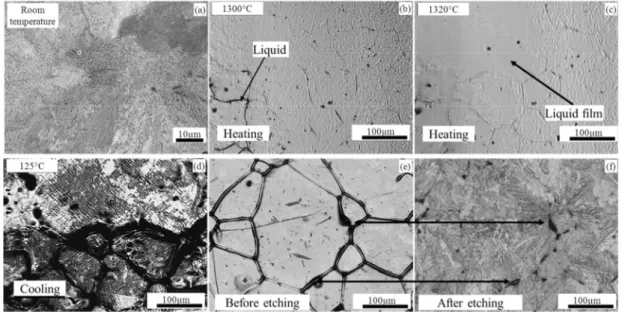
For 100Cr6, the microstructure evolution is shown in Fig. 5. After the austenization transformation (perlite to austenite) at ~750°C during heating, the liquid appeared along the grain boundaries. There was a significant increase in liquid content with a small temperature increase (~20°C), as compared between Fig. 5 (b) and (c). During cooling, the austenite and liquid experienced several phase transformations and finally transformed to perlite, as shown in Fig. 5 (d). By comparing Fig. 5 (e) and (f), the pearlite was well observed by optical microscope on the CLSM investigated samples. However, it is difficult to correlate the final microstructure at room temperature with that in the semi-solid state.
For M2, the microstructure with small grain size and isolated carbides before reaching the austenization temperature (~880°C) was observed as shown in Fig. 6 (a). When reaching the austenization temperature, the alloying elements started diffusing into austenite (Fig. 6 (c)). However, the alloying elements content was too high to be totally dissolved. Furthermore, according to the phase diagram of M2, the M6C and MC carbides dissolve in the semi-solid range, but at
different start dissolving temperature. The MC carbides dissolve first, while M6C dissolves later.
Upon entering the semi-solid state, liquid appeared along the grain boundaries and the alloying elements diffused into the liquid phase and penetrated the grain boundaries. In addition, some small liquid droplets were observed inside the grains (Fig. 6 (d) and (e)) because of local small carbides particles. Kleiner et al. [16] described this phenomenon as self-blocking. During cooling, the liquid phase became new carbides since liquid was rich in alloying elements. It was also found that the new carbides have the same size and distribution as that of liquid phase in the semi-solid state (Fig. 6 (f)). After several solid-solid transformations (Fig. 6 (g) and (h)), the martensite matrix with inter-connected carbides were obtained confirmed by SEM observations (Fig. 6 (i)).
Fig. 5. (a). SEM micrograph of 100Cr6 in the as-received state. (b)-(d). HT-CLSM snapshots for the sequence of partial remelting of 100Cr6 during heating at 200°C/min to a peak temperature of 1400°C and the subsequent
cooling, (e) sample surface after cycling and (f) optical micrograph of the material shown in (e).
Fig. 6 . (a)-(i). HT-CLSM snapshots for the sequence of partial remelting of M2 during heating at 200°C/min to a peak temperature of 1250°C and the subsequent cooling. [15]
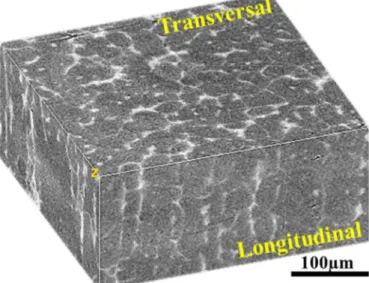
As mentioned before, a proper microstructure with a suitable amount of liquid is necessary for successful thixoforming process. Generally, the liquid fraction as a function of temperature for steel grades depends on the chemical compositions and their distributions. Liquid fraction could be evaluated by DSC/DTA methods. For some steel grades, whose microstructure in the semi-solid state can be preserved by quenching, the liquid fraction could be determined by quantitative image analysis. However, as shown in Fig. 3, the microstructure of C38LTT and 100Cr6 at low liquid fraction could not be frozen by quenching. Thus the liquid fraction can not be evaluated by quenching experiments. Meanwhile, the microstructure evolution during heating is influenced by the manufacturing route, the distribution of chemical compositions as well as thermal history. For a given steel grade, the microstructure evolution could be investigated by CLSM. It could be seen that the liquid initiated in the grain boundaries during heating the grades. Although it was difficult to quantify the liquid fraction as a function of temperature due to the small field of view, it could be seen obviously that the liquid contents increased with temperature. However, the semi-solid range of C38LTT and 100Cr6 was relatively small as compared to that of M2. That means a higher precision should be required in temperature control for C38LTT and 100Cr6 during thixoforming. Considering the DSC results, the processing temperature ranges for C38LTT, 100Cr6 and M2 are (~1420 – ~1450°C), (~1360 – ~1410°C) and (~1290 – ~1340°C), respectively. Besides the liquid fraction, the morphology in the semi-solid state affects the thixoforging process significantly. Although the microstructure of the grades in the semi-solid state was not the classical one for thixoforging process, but is composed of equiaxed solid grains surrounded by liquid matrix. A structure with more spheroidal grains could be obtained with holding time. However, considering the industrial conditions, the long holding time was not used. By comparing the grain size of the steel grades in the semi-solid state, it was found that the average grain size of M2 was much smaller than that of C38LTT and 10Cr6, caused by the pinning ability of the carbides. From the CLSM results, it was found that the microstructure of M2 in the semi-solid could be preserved even by a low cooling rate. Meanwhile, it made the X-ray microtomography on M2 for 3D microstructure characterization possible because of its high content of alloying elements. A detail reconstruction of 3D stacks of M2 was explained in Ref. [15]. The solid skeleton of M2 in the semi-solid state could be observed as shown in Fig. 7. The solid skeleton is useful to support the sample and prevent it from collapsing prior to forming process.
Fig. 7. 3D stack of M2 in the semi-solid state obtained by X-ray microtomography.
Conclusions
The microstructure evolution of C38LTT, 100Cr6 and M2 has been investigated by different techniques. The CLSM provides a possibility to directly investigate the microstructure at high temperature. Depending on the chemical composition and manufacturing process, the melting behavior of each grade was described. Combining the DSC, the CLSM results confirm that the
temperature sensitivity of C38LTT and 100Cr6 is much higher which brings a difficulty in the temperature control for thixoforging. Beside 2D observation, the 3D microstructure of M2 was investigated. The solid skeleton was observed at low liquid fraction. It is used to support the billet and prevent it from collapsing prior to the thixoforging process.
Acknowledgements
The authors acknowledge the helpful discussions with Joris Van Dyck and Muxing Guo at the Catholic University of Leuven. They also warmly thank Marc Wary (Arts et Me ´tiers ParisTech CER Metz) for his technical support and advice.
References
[1] D. Spencer, R. Mehrabian, M.C. Flemings, Metallurgical and Materials Transactions B, 3 (1972) 1925-1932.
[2] D.H. Kirkwood, M. Suéry, P. Kapranos, H.V. Atkinson, K.P. Young, Semi-solid Processing of Alloys, Springer, 2010.
[3] H. Atkinson, A. Rassili, International Journal of Material Forming, 3 (2010) 791-795. [4] G. Hirt, R. Kopp, in, Wiley-VCH Verlag GmbH & Co. KGaA, Aachen, 2009, pp. 477. [5] D.H. Kirkwood, C.M. Sellars, L.G. Elias Boyed, in, 1991.
[6] K.P. Young, C.P. Kyonka, J.A. Courtois, in, USA, 1982.
[7] M.Z. Omar, A. Alfan, J. Syarif, H.V. Atkinson, Journal of Materials Science, 46 (2011) 7679-7705.
[8] J. Li, S. Sugiyama, J. Yanagimoto, Y. Chen, G. Fan, Journal of Materials Processing Technology, 208 (2008) 165-170.
[9] R. Bülte, W. Bleck, Steel Research International, 75 (2004) 588-592.
[10] E. Becker, R. Bigot, L. Langlois, The International Journal of Advanced Manufacturing Technology, 48 (2010) 913-924.
[11] R. Bigot, V. Favier, C. Rouff, Journal of Materials Processing Technology, 160 (2005) 43-53. [12] E. Becker, V. Favier, R. Bigot, P. Cezard, L. Langlois, Journal of Materials Processing Technology, 210 (2010) 1482-1492.
[13] N. Limodin, L. Salvo, M. Suéry, M. DiMichiel, Acta Materialia, 55 (2007) 3177-3191.
[14] A. Reichmann, P. Poelt, C. Brandl, B. Chernev, P. Wilhelm, Oxidation of Metals, 70 (2008) 257-266.
[15] G.C. Gu, R. Pesci, E. Becker, L. Langlois, R. Bigot, M.X. Guo, Acta Materialia, In press (2013). [16] S. Kleiner, O. Beffort, P.J. Uggowitzer, Scripta Materialia, 51 (2004) 405-410.


