Science Arts & Métiers (SAM)
is an open access repository that collects the work of Arts et Métiers Institute of
Technology researchers and makes it freely available over the web where possible.
This is an author-deposited version published in: https://sam.ensam.eu Handle ID: .http://hdl.handle.net/10985/11323
To cite this version :
Hussein ZAHR, Eric SEMAIL, Bassel ASLAN, Franck SCUILLER - Maximum Torque Per Ampere Strategy for a Biharmonic Five-phase Synchronous Machine - In: 2016 International Symposium on Power Electronics, Electrical Drives, Automation and Motion (SPEEDAM), Italie, 20160622 -23rd International Symposium on Power Electronics, Electrical Drives, Automation and Motion (SPEEDAM) - 2016
Any correspondence concerning this service should be sent to the repository Administrator : [email protected]
Maximum Torque Per Ampere Strategy for a
Bi-harmonic Five-phase Synchronous Machine
Hussein ZAHR, Eric SEMAIL, Bassel ASLAN
Univ. Lille, Centrale Lille, Arts et Metiers ParisTech, HEI, EA 2697 - L2EP - Laboratoire d’Electrotechnique et
d’Electronique de Puissance, F-59000 Lille, France [email protected], [email protected]
Franck SCUILLER
Research Institute of Naval Academy Ecole Navale
Brest, France [email protected]
Abstract—The paper studies the impact of first and third
current-harmonic repartition in a five-phase Permanent Magnet machine whose Electromotive Forces (emfs) have first and third harmonics of the same amplitude. With a five-phase machine, it is possible for the torque production to achieve independent controls of the first and third harmonics of currents by using a vector control in each one of the two characteristic orthogonal sub-spaces of the machine. The same torque quality as obtained with a three-phase machine with sinusoidal emf can be thus obtained with a non-sinusoidal emf and with one more supplementary degree of freedom for the control. Based on the Maximum Torque Per Ampere (MTPA) strategy used for three-phase machines, a comparison of the obtained torque/speed characteristics of the machine is achieved using either one or two harmonics. The voltage limits imposed by the Voltage Source Inverter and two different values of the maximum allowed current densities are taken into account for obtaining the optimum repartition between first and third harmonics of currents: it appears that at first, from the point of view of efficiency, the MTPA is not optimal except for low speeds and secondly that the repartition of currents is not trivial and depends for example on the considered maximum current densities.
Keywords—Interior magnet machine; Multi-phase machines; Maximum Torque Per Ampere; Copper losses, Core loss, PM losses, effeciency
J current density in (A/mm2)
cond
S conductor surface
Tem Torque produced by the machine
1
I first harmonic current amplitude
3
I third harmonic current amplitude
1
first harmonic current phase
3
third harmonic current phase
dc
V voltage of DC bus .
s
R stator resistance of one phase
phase flux
1 d
flux of d axis in primary machine
1 q
flux of q axis in primary machine
3 d
flux of d axis in secondary machine
3 q
flux of q axis in secondary machine p number of poles pairs.
1 d
i current of d axis in primary machine
1 q
i current of q axis in primary machine
3 d
i current of d axis in secondary machine
3 q
i current of q axis in secondary machine I. INTRODUCTION
Nowadays, researches intensively explore multi-phase machines due to their advantages such as high torque density and fault tolerance but also for a more basic reason: the current per phase is reduced when the phase number increases. For a given value of DC bus voltage, the number of phases is now a design parameter when chosing the adequate power components [1-3]. It is currently the case for very high power drives (>5 MW) with IGBT transistors or for very low voltage (<48V) drives of significant power (>10kW) with MOSFET transistors. These advantages make multi-phase drive a preferred choice especially in embedded marine and hybrid automotive systems with fault-tolerant capability and low volume and mass allocation. The compactness of these multiphase machines is due to their ability to produce torque without pulsation even with sinusoidal currents and non-sinusoidal emfs [4-5]. The higher the number of phases is, the higher the number of harmonics which can contribute to the the torque production is and this can be done with a simple vector control similar to the one of a three-phase machine with sinusoidal emf. Fault-tolerant and discrete submarines are thus using twelve or twenty six phases [6]. Nevertheless, a high number of phases impact the cost since the number of drivers and current sensors is increased. Therefore a trade-off between torque density, control and cost has to be found when choosing the number of phases. Consequently, the choice of five phases appears, for low cost applications, as the first solution which allows the utilization of both first and third harmonic current to produce torque. Since the five-phase machine has two degrees of freedom for the control, searching
the optimal currents that maximize torque is a complex problem, especially in the flux weakening zone [7] when working within limits for voltages and currents. The problem is still becoming more difficult when taking into account saturation, saliency and the coupling between the variables, in addition to other minor effects-generally neglected-like slot effect and the emf harmonics. In fact, neglecting any of this behavior can lead either to underestimation or overestimation of the machine performances [8][9]. Under all this assumptions, it is quite difficult to find analytically the optimal current references. So we have to solve the problem numerically.
In this paper, the aim is to explore the maximum capacity of the machine when the Maximum Torque Per Ampere strategy is applied taking account the whole saturation effects (currents, voltages and flux). In order to analyze the impact of bi-harmonic control, a comparison is done with the two cases where only one harmonic is considered. In section II, elements of the special bi-harmonic machine are given. In section III, the torque/speed characteristics obtained when operating at the voltage/current limits under MTPA strategy are given.
II. MACHINE DESIGN
A. Choice of slots/poles combination
Of course, the practical torque contribution of each harmonic depends on its amplitude in the emf that depends itself on the rotor structure (magnet distribution and iron geometry) and the stator winding distribution. Among many possible interesting combinations and distributions of winding, the fractional-slot concentrated ones with number of slots per pole and per phase Spp=0.5 is privileged in automotive 3-phase machine design[4][10].In fact, thiswinding distribution does not produce low (sub)harmonic in the MMF spectrum, then protecting the machine from harmful low-order harmonics rotating asynchronously with rotor and inducing eddy current losses in the conductive parts of rotor including magnets and iron[4][11]. Furthermore, in five-phase machine with Spp=0.5, the winding factors of the third and first harmonics are 0.951 and 0.588 respectively, thus increasing the third harmonic back-emf term: the machine is then capable to provide torques of the same order from both first and third harmonic if a suitable rotor is introduced[4][12]. Many magnet rotor can be used : Interior magnet, surface mounted magnets, inset machines. The interior permanent magnet rotor seems to be the better choice referring to the others:
Interior magnet structures allow the flux concentration which boosts torque and improve torque density. A mechanical and magnetic protection of magnets are
insured. The iron around magnets prevent the MMF harmonics to cross the magnets, instead they cross the iron. Thus, low PM losses can be expected, which improves efficiency referring to surface mounted PM machines, where harmful harmonics directly cross the magnets, which causes significant losses.
Large flux weakening area due to the possibility to obtain higher value of Ld.
Reluctant torque in addition to torque from Permanent Magnet, which improve machine.
Consequently, the use of winding which Spp=0.5 with Interior magnets rotor can lead to very low permanent magnet losses, thus making possible very high speed operation without magnet demagnetization hazard. This point is very important when designing electrical machines with wide flux weakening area, for marine or automobile applications for instance. As mentioned above, the fractional-slot concentrated winding is used. For five-phase machine and Spp=0.5, different combinations slots/poles are possible:
5/2;10/4;20/8;40/16;...
/ polesslots
The number of poles is chosen in order to limit the electrical frequency at a given rotation speed, thus helping to limit the resulting machine losses. 8 poles seems to be a good trade-off among the available choices, this combination also guarantees low losses in permanent magnet . Consequently, our machine is 20 slots 8 poles 5 phases with interior permanent magnets. Some machine parameters are given in table (I):
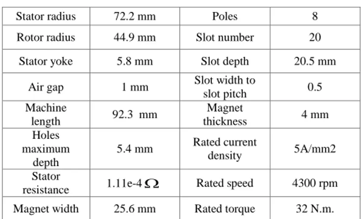
TABLE I. GEOMETRICAL MACHINES PARAMETERS Stator radius 72.2 mm Poles 8 Rotor radius 44.9 mm Slot number 20
Stator yoke 5.8 mm Slot depth 20.5 mm Air gap 1 mm Slot width to slot pitch 0.5 Machine length 92.3 mm Magnet thickness 4 mm Holes maximum depth 5.4 mm Rated current density 5A/mm2 Stator
resistance 1.11e-4 Rated speed 4300 rpm Magnet width 25.6 mm Rated torque 32 N.m.
B. Stator and rotor structure
Given the number of slots and poles, the machine has a periodicity equal to the greatest common divisor of the number of slots and poles. For this machine, the periodicity is equal to 4; consequently, the quarter of the machine (5 slots and 2 poles) represents the full winding pattern. The winding distribution is represented by the winding distribution matrix D given by [12]:
1 1 0 0 0 0 1 1 0 0 0 0 1 1 0 0 0 0 1 1 1 0 0 0 1 2 1 D (1)The term D(m,n) represents the conductor of the phase n in the slot m, so each term represents for which phases the conductors in a slot belong to. +1 represents a forward conductor and -1 a backward conductor. The choice of
winding distribution should be accomplished by the design of a structure to satisfy the functionalities defined in the introduction.The classical rotor structure does not allow to obtain a significant third harmonic in the flux spectrum referring to the first harmonic. In fact, we need to modify the rotor structure to achieve this goal. In [4], the authors describe a new rotor structure that contains additional magnets in the rotor, which can boost the third harmonic flux. Similarly without adding extra magnets, we choose to introduce holes in the middle of the pole pitch, thus significantly changing the flux embraced by the winding. The new rotor structure is called "bi-harmonic rotor”. As shown in[13], the improvement of the third harmonic in rotor can increase the flux density in the air gap, thus reducing the copper losses. Figure (1) shows the winding distribution and illustrates the differences between the classical structure of rotor (-a) and the new structure allowing to boost the third harmonic flux (-b).Notice that the winding star connection is adopted for this machine.
(a) (b)
Fig.1. Rotor structure. a)mono-harmonic rotor, b) bi-harmonic rotor[4].
(a) (b)
Fig.2. Comparison of flux between mono-harmonic and bi-harmonic rotors. a) Spectrum of flux. b) flux waveform.
(a) (b) Fig.3. back-emf of bi-harmonic rotor. a) Waveform. b) Spectrum.
Figure (2)-a and (2)-b shows respectively in red the magnetic flux spectrum and waveform of the bi-harmonic rotor. It can be observed that the amplitude of third harmonic is significant. In figure (3), the corresponding emf is given. Compared with the three phase machines which are controlled in only one
) ,
(
sub-space obtained by applying the Concordia transformation, a five-phase can be controlled in two orthogonal sub-spaces (1,1)and(
3,
3)
defined by a Concordia transformation extended to five-phase machines. Each sub-space represents a fictitious machine, which are mechanically coupled and rotates are the same speed rotation. The first machine is called primary machine and the other secondary machine. Projection of the back-emf into the sub-spaces is represented in figure (4)- over two electrical periods:Fig.4. Projection of the back-emf in (1,1)and ( , ) 3 3
sub-spaces For the projection into the sub-spaces (1,1)(primary machine) we can observe harmonics 1 and 9 whereas, for the projection into sub-space ( , )
3 3
(secondary machine), only the third harmonic effect is visible since the other harmonics terms are very low. This result is in accordance with the property of harmonic repartition for balanced vectors between the two-subspaces [4-14]. Given that the star connection is adopted and assuming a sinusoidal emf in each sub-space, therefore, three strategies of control are possible: supply with the first harmonic, supply with the third harmonic and supply with both harmonics in opposition with three-phase machine where it is possible to supply the machine by only one harmonic.
III. TORQUE/SPEED CHARACTERISTICS UNDER MTPA CONTROL As previously explained, this machine with bi-harmonic rotor can be supplied by the first current harmonic, the third or both. In this part, we aim to determine for the three supply strategies, the torque/speed characteristics.
A. MTPA problem formulation
Since each harmonic is associated to rotating dq-plane, the two dq- plane being orthogonal, the current density in one phase is given by : cond S I I J 2 2 3 2 1 (2) For the three supply strategies the current density is chosen to 10 A/mm2 for transient operations and 5A/mm2 for steady state operations. The DC bus is always 48 V.
I represent the current in the phase a, given by: ) 3 cos( ) cos( 1 3 3 1
I t I t IThe MTPA problem is formulated as follow:
) ( max em
x T
Where x
I1
1 I3
3
, subject to contraints : 24 ) max( max phase V J J (3)
Where Vphase is the peak value of voltage in a phase (i.e. phase
1) given by (4): dt d I R Vphase s (4) and Jmax is the maximum current density allowed,
is the flux in a phase. Due to significant saturation effect and complex magnetic circuit of PMSM, the inductances may vary largely during operation, which makes the analytical estimation difficult, in addition to the saliency effect. The saturation effect is mainly driven by the current density value. Consequently, we need to evaluate the parameters of the inductance matrix under several load conditions as proposed in [15][16][17]. In order to obtain a complete numerical model of the machine, the flux is simulated using the finite element FE under 4356 load conditions. For each current vector corresponding to a load condition, the flux winding is calculated numerically. Generally the expression of flux is:) , , , ( ) , , , (d1 q1 d3 q3 magnet d1 q1 d3 q3 winding phase i i i i i i i i (5) Where [id1;iq1;id3,iq3] is the current expressed in (d1,q1,d3,q3)
frame obtained by the Park transformation over the current in )
, , , ,
(o1 1 3 3 frame. The homopolar component is zero since winding is star connected.
The mean torque expression, used in the objective function is calculated as follow:
)
(
3
)
(
d1q1 q1d1 d3q3 q3d3 emp
i
i
p
i
i
T
(6) where p is the poles pairs number. In fact, (6) is used toestimate the mean torque value, based on the flux calculated numerically. It should be highlighted that this model takes into account the magnetic coupling that exists between the two fictitious machines and the axis (d,q) in the same machine. Furthermore, saturation effect is considered in flux calculation. Taking into account these aspects can lead to better use of the allowed DC bus. It is worth noting that the purpose of this study is to determine the maximum torque that can be provided by the machine for each speed under current and voltage constraints. In the following sections, we will determine the torque/speed characteristic for each supply strategy.
B. Torque/Speed Characteristics for two values of current density constraints
In this part, the MTPA is solved for two values ofJmax: 5A/mm2 and 10A/mm2. As mentioned above, the machine can be supplied either by first harmonic current, or third harmonic or both. For each value of current density, we will solve the MTPA problem for each current supply strategy.
a) Problem resolution for J5A/mm2
In this part the current density is less or equal to 5 A/mm2 for the three supply strategies. Since the back-emf of the third harmonic amplitude is larger than the first harmonic as we can see in figure (3), the secondary machine is able to produce more torque than the primary machine for the same current density. And the primary machine has a base speed greater than the secondary machine.
The problem resolution leads to the torque/speed characteristic presented in figure (5). As we can observe, with the secondary machine (or the third harmonic supply), the machine can provide more torque than the primary machine for the same current density. Furthermore, the supply of the machine by first and third harmonic together boosts the torque. It is worth noting that we have to reduce the current density for all the speeds above the base speed (> 3200 rpm) for the third harmonic supply to guarantee the maximum torque when exceeding the base speed.
fig.5. Torque/Speed characteristic for the each supply strategy(Jmax=5A/mm2) The current density for each strategy in function of rotation speed is given in figure (6), where the values are normalized with respect of the maximum current density Jmax (equal to 5A/mm2 in this part).
fig. 6. Current supply for each control strategy (Jmax=5A/mm2)
b) Problem resolution for J10A/mm2
Now the problem is solved for a current density less or equal to 10 A/mm2 for each supply strategy. Figure (7) represents the resulting torque/speed characteristic. The secondary machine is supposed to provide more torque than the primary machine for the same current density, but in this case, we observe the opposite. This is due to the magnetic saturation effect of the machine when supplied by the third harmonic current with 10A/mm2 current density.
Fig.7. Torque/Speed characteristic for the each supply strategy (Jmax=10 A/mm2)
Figure (8) gives an insight of the machine flux densities for two cases: first harmonic supply and third harmonic supply for the same current density. As it can be observed, the machine is saturated when it’s supplied by the third harmonic current with a flux density exceeding 2 T in some spots of the machine, teeth in particular.
(a) (b)
Fig.8.Magnet flux density variation for J=10A/mm2 (a) First harmonic supply. (b) Third harmonic supply.
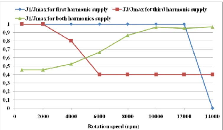
The current density for each rotation speed with repect to Jmax is given by figure (9). It can be noted that, even if the ratio J1/Jmax is constant in the case of both harmonics supply, the phase angles of the first and the third harmonic currents change to maintain constant the voltage at speed higher than 6000rpm.
Fig. 9. Current supply for each control strategy (Jmax=10 A/mm2)
Other than boosting torque, the simultaneous injection of the two current harmonics makes wider the flux weakening area and allows the machine to produce torque at very high speed under the same DC bus. Voltage induced by each current harmonic compensates the voltage produced by the other harmonic. As in the previous case where the current density is less than 5A/mm2, the current density should be reduced in the case of the third harmonic supply when exceeding base speed (>1700 rpm), and when exceeding 10000rpm for the first harmonic supply. However, we continue to supply the machine by 10 A/mm2 for the harmonic injection over all the studied speed range.
IV. ANALYSIS OF LOSSES AND EFFICIENCY WITH MTPA STRATEGIES
Generally, MTPA strategy targets minimization of copper losses without taking into account other losses like core losses and PM losses. So, it is important to examine the evolution of these losses for the optimal torque/speed characteristic founded in part III. In addition on frequency, these losses may also depend on the amplitude of the third harmonic current and the corresponding phase. Losses calculation is followed by efficiency calculation.
a) Analysis of losses and efficiency for J5 A/mm2
In this section, a calculation of the total losses which includes copper losses, core losses and PM losses is performed for the torque speed characteristic founded in part (III.B.a). Ansoft Maxwell 2D software is used to evaluate these losses. Figure (10) shows the corresponding results. Based on the results in figures (5) and (10), we can determine the efficiency versus speed for each supply strategy, which is represented in figure (11). At low speed (<2000 rpm), the machine supplied with both current harmonics has the higher efficiency, this is due to the fact that this strategy enhances torque in comparison of the two other strategies and the losses are
equivalent for three strategies as it can be observed in figure (10).
Fig.10. Losses vs. speed for each supply strategy (Jmax=5 A/mm2).
Thus, at low speed the MTPA strategy with both current harmonics is the best one when searching to maximize efficiency, but it seems not be optimal when searching to minimize losses. Between 2000 rpm up to 6000 rpm, it appears that if the required torque is lower than 22 Nm as seen in figure (5) than it is better to use only the first harmonic which is the optimal control when searching for maximize efficiency and minimize losses.
Fig.11. Efficiency vs. speed characteristic for the each supply strategy (Jmax=5 A/mm2).
On contrary, the injection of third harmonic component with the first harmonic is necessary when the required torque is higher. Above 6000rpm the injection of both harmonics provides the highest efficiency and the lowest losses. It is probable that the corresponding current waveform produces less core and magnet losses than with only one harmonic. When supplied with only the third harmonic, the efficiency is low in comparison with the two other supply strategies. Consequently, third harmonic current alone should be avoided. In the case of first harmonic supply, the only factor that influences losses is the frequency. However in the case of the strategy of both harmonics, losses depend not only on frequency but also depend on the distribution of the current density between harmonics 1 and 3. At a given speed, if the third harmonic is very significant with respect to the first harmonic, we will expect high losses especially when
functioning at high speed. This is the case of the speeds between 2000 and 6000 rpm in figure (5) where we have significant third harmonic current with respect to the first harmonic current, and this explains why efficiency is low when comparing with the first harmonic supply strategy, but we have to consider the very large torque gain. When speed exceeds 6000 rpm, the contribution of the secondary machine is reduced either by the reducing current density or flux weakening. Consequently, the efficiency becomes better than the first harmonic current supply as we can observe in figure (7).
In this part, we studied three supply strategies applied to the machine. The current density is less or equal (J5A/mm2). The supply of the machine with both the first and third harmonic current is the better strategy that guarantees higher torque with better efficiency depending on the speed range. However, when considering losses, this strategy becomes more interesting at high speed (>8000 rpm).In the next section, the current density will be less or equal to 10 A/mm^2 and the same supply strategies will be applied
b) Analysis of losses and efficiency for J10 A/mm2
In this section, the current density is 10A/mm2. This current density is used in transient operation where we need high torque for a short time. Losses are calculated also for these cases. Figure (12) shows the corresponding results. Based on figure (7) and (12), the efficiency is evaluated as we can observe in figure (13).
Fig.12.Losses vs speed characteristic for each supply strategy (Jmax=10 A/mm2).
Fig.13.Efficiency vs. Speed characteristic for each supply strategy (Jmax=10 A/mm2).
From figure (11), the same conclusion as in the previous part can be drawn: the injection of the third harmonic alone in the machine should be avoided. The efficiency of this strategy is always the worst among the strategies. For the two other strategies, the efficiencies are equivalent for speeds lower than 8000 rpm. The injection of both harmonic becomes interesting at high speed (higher than 8000 rpm). However, taking into account losses, the injection of the two harmonics may not be the optimal solution when considering thermal limitations of the machine. This strategy has the highest losses. The use of such supply must be limited to transient operation where high toque is required for a short time.
V. CONCLUSION
In this paper, Maximum Torque Per Ampere Strategy taking into account Voltage limitation was applied to five-phase interior permanent magnet synchronous machine with a special rotor structure enhancing the third harmonic in the back-emf. Three control strategies are considered for this machine: first harmonic current supply, third harmonic current supply or both. Even if the winding factor is much higher for the third harmonic, it appears that the supply of the machine only by the third harmonic is never the best solution. Using both harmonics is always more interesting but not always because the two harmonics directly contribute each other to the torque production. With 10A/mm2 current density, the injection of third harmonic at high speeds (8000-14000 rpm) allows, when saturation of voltage occurs, to impose higher amplitude of first harmonic current, the torque due to the third harmonic being small. Moreover, it appears that if MTPA is optimal for torque production at given copper losses, it is not optimal at given losses, except at low speeds when core and Permanent Magnet Losses are negligible. For instance, it appears that between 2000 rpm and 6000 rpm, if high torque is required, first and third harmonic current can be injected but with a decrease of efficiency. So, the problem needs to be solved introducing core losses in optimization process which calculate current references. A new algorithm, searching to obtain Maximum Torque for a given level of total losses should be implemented.
REFERENCES
[1] E.Levi, “Multiphase electric machines for variable speed applocations,”
IEEE on Trans. on Industrial Electronics, vol.55, no.5, pp.1893-1909,
2008.
[2] F.Scuiller, E. Semail and J.F. Charpentier, “Muli-crietiria based design approach of multi phase permanent magnet low-speed synchronous machines,” IET Electr. Power appl., 2009, vol.3, Iss.2, pp.102-110. [3] L. Parsa, “On advantage of multi-phase machines ,” Proc. IEEE-IECON
2005 annual meeting, 6-10 November 2005.
[4] B.Aslan, E.Semail, “New 5-Phase Concentrated Winding Machine Bi Harmonic Structure for Automotive Application,” IEEE XXIth
International conference on Electrical machines (ICEM),
Berlin-Germany, September 2014.
[5] B.Aslan, E.Semail and J.Lagranger, “General Analytical Model of Magnet Average Eddy-Current Volume Losses for Comparison of Multi-phase PM Machines with Concentrated Winding,” IEEE Trans.
on Energy Conversion, Vol. 29, no. 1, pages. 11, March 2014.
[6] J.Eckert Siemens, “ Method for operating a submarine and submarine,” patent, WO2012143210 , 26.10.2012.
[7] Li. Lu, B.Aslan, L.Kobylanski, P.Sandelscu, F.Meinguet, X.Kastelyn and E.Semail, “Computation of optimal Current references for flux-weakening of Multi-phase Synchronous machine,” IECON (38 th
annual conference of the IEEE Industrial Electronics society), Canada,
2012.
[8] L.Parsa, K.Namhum and H.A. Toliyat, “Field weakening Operation of High Torque Density Five-Phase PM motor drives, ” Proceedings of
IEEE International confrence on Electric machines and drives (IEMDC2005), pp.1507-1512, 2005.
[9] S. Xuelein W.Xuhui and C.Wei, “research on field weakening control of multi-phase PM synchronous motor,” (ICEMS) 2011 International
conference on Electrical machines and Systems, Aug 2011.
[10] A.M. El-Refaie, “Fractinnal-Slot concentrated windings synchronous permanent magnet machines : opportunities and challenges,” IEEE
Trans. on Industrial Electronics, vol.5, no.1, pp.107-121, Jan 2010.
[11] N.Bianchi and E. Fornasiero “Impact of MMF space harmonic on rotor losses in fractionnal-slot permanent-magnet machines,” IEEE Trans.On
Energy Conversion,vol.24,no.2, June 2009
[12] F.Scuiller, E.Semail and J.F.Charpentier, “General modeling of the windings for multi-phase machines: Application for the analytical estimation of mutual stator inductance for smooth air gap machines”
Eur. Phys. J. Appl. Phys. 50, 31102 (2010).
[13] J. Pyrhonen, P.Kurronen and A. Paraviainen, “General modelling of the windings for multi-phase machines-Application for the analytical estimation of mutual stator inductance for smooth air gap machines,”
IEEE XVIIth International conference on Electrical machines (ICEM),
Crete Island, Greece 2006.
[14] X. Kestelyn, E. Semail , “Vectorial Modeling and Control of Multiphase Machines with Non-salient Poles Supplied by an Inverter,” Chap7 in
book “ Control of Non-conventional Synchronous Motors”, ISTE Ltd
and John Wiley & Sons Inc, 2012, 44 pages.
[15] N.Bianchi, S. Bolognani, “Magnetic Models of saturated Interior Permanent Magnet motors based on Finite Element Analysis,” The 1998
IEEE Industry Applications Conference, Thirty-Third IAS Annual Meeting. October 1998.
[16] X.Jiang, B.Wang, W.Li and H.Zhu , “Inductance Parameter Simulation Analysis and Measurement of Permanent magnet synchronous motors, ”
Trans tech Publications, Switzerland,Advanced Materials research Vol
651(2013) pp931-936.
[17] A. Soualmi, F. Dubas, D. Dépernet, A. Randria, and C.Espanet, “Inductances estimation in the d-q axis for an interior Permanent-Magnet synchronous machines ,with Distributed windings, ” IEEE 2012