UNIVERSITÉ DE SHERBROOKE
Faculté de génie
Département de génie mécanique
Isolation et absorption acoustiques à l'aide de
mousses actives
Acoustic Isolation and Absorption with Smart Foams
Mémoire de maîtrise
Spécialité : génie mécanique
Abhishek KUNDU
Jury: Alain Berry (directeur)
Patrice Masson
Noureddine Atalia
Sherbrooke (Québec) Canada
April 2010
?F?
Canada Published Heritage Branch 395 Wellington Street OttawaONK1A0N4 Canada Archives Canada Direction du Patrimoine de l'édition 395, rue Wellington Ottawa ON K1 A 0N4 CanadaYour file Votre référence
ISBN: 978-0-494-70752-4 Our file Notre référence ISBN: 978-0-494-70752-4
NOTICE:
The author has granted a
non-exclusive license allowing Library and
Archives Canada to reproduce,
publish, archive, preserve, conserve, communicate to the public by
telecommunication or on the Internet, loan, distribute and sell theses
worldwide, for commercial or
non-commercial purposes, in microform, paper, electronic and/or any other formats.
AVIS:
L'auteur a accordé une licence non exclusive permettant à la Bibliothèque et Archives Canada de reproduire, publier, archiver, sauvegarder, conserver, transmettre au public par télécommunication ou par l'Internet, prêter, distribuer et vendre des thèses partout dans le
monde, à des fins commerciales ou autres, sur
support microforme, papier, électronique et/ou autres formats.
The author retains copyright ownership and moral rights in this thesis. Neither the thesis nor substantial extracts from it may be printed or otherwise reproduced without the author's permission.
L'auteur conserve la propriété du droit d'auteur et des droits moraux qui protège cette thèse. Ni la thèse ni des extraits substantiels de celle-ci ne doivent être imprimés ou autrement
reproduits sans son autorisation.
In compliance with the Canadian Privacy Act some supporting forms may have been removed from this thesis.
Conformément à la loi canadienne sur la protection de la vie privée, quelques formulaires secondaires ont été enlevés de cette thèse.
While these forms may be included in the document page count, their removal does not represent any loss of content from the thesis.
Bien que ces formulaires aient inclus dans la pagination, il n'y aura aucun contenu
manquant.
¦+¦
RÉSUMÉ
Les mousses actives sont des solutions composites de contrôle du bruit qui combinent les avantages complémentaires du matériau en mousse passif et des actionneurs piézo-électriques répartis spatialement à l'intérieur des mousses. Une étude sur le problème de
l'amélioration de l'indice d'affaiblissement des mousses actives en utilisant des stratégies
de contrôle actif a été effectuée à la fois numériquement et expérimentalement à l'intérieur
d'un guide d'onde sous la condition de propagation en ondes planes. Trois différents
mod-èles de prototypes de mousse active ont été pris en compte dans les simulations par élé-ments finis et leur efficacité à annuler l'onde transmise en aval de la mousse active a été étudiée. Des études expérimentales afin d'optimiser l'indice d'affaiblissement des mousses actives sous une commande prédictive SISO avec un microphone unidirectionnel commecapteur d'erreur démontrent que l'efficacité du contrôle sur une large gamme de fréquences
est bonne. Le problème physique de l'annulation de la propagation des ondes sonores est étudié en détail dans les simulations numériques et elles apportent un éclairage précieux sur l'altération de la réponse vibratoire de l'actionneur piézo-électrique de la mousse active sous contrôle optimal. Les résultats des simulations ont aussi contribué à l'identification destratégies de contrôle de rechange pour l'atténuation de l'onde sonore transmise à l'aide de
la réponse sensorielle de l'actionneur distribué. On peut pour cela remplacer éventuelle-ment l'utilisation de microphones en champ lointain et ainsi améliorer notableéventuelle-ment la compacité du système de contrôle actif. La réponse sensorielle d'un piezo-actionneur, en raison de sa déformation mécanique est indépendante de la réponse de sa charge totale, avec la compensation analogique-numérique hybride de la "capacite feedthrough" de l'ac-tionneur, à l'aide d'un algorithme adaptatif. Cette charge mécanique de réponse s'est révélé être une bonne approximation de la vitesse radiale du volume de l'actionneur, et peut êtreutilisée comme signal d'erreur pour maximiser l'indice d'affaiblissement du système de
mousse active. En outre, elle a été utilisée dans l'absorption et les problèmes de contrôle TL, fonctionnant sur une erreur de stratégie virtuelle de détection, et a produit lesrésul-tats souhaités sur une large plage de fréquences. Le succès du principe capteur/actionneur
dans les problèmes de contrôle actif du bruit peut donner des améliorations importantes en termes de positions et de configurations de capteurs d'erreurs associés aux systèmes decontrôle actif.
Mots-cls : Mousses actives, isolation acoustique, contrôle actif du bruit, fx-LMS
ABSTRACT
Smart foams are composite noise control solutions which combine the complimentary
ad-vantages of the passive foam material with the spatially distributed piezoelectric actuator
embedded in it. Investigation of the problem of improving the transmission loss of smart
foams using active control strategies has been done both numerically and experimentally
inside a waveguide under the condition of plane wave propagation. Three different
de-signs of the smart foam prototypes have been considered in the finite element simulations
and their effectiveness in canceling the transmitted wave downstream of the smart foam
has been studied. Experimental studies to optimize the transmission loss of the smart
foams under SISO feedforward control with an unidirectional microphone as the error
sen-sor demonstrates good control efficiency over a broad range of frequencies. The physical
problem of cancellation of the propagating sound waves is studied in detail in the
nu-merical simulations and they provide valuable insight on the alteration of the vibration
response of the piezo-actuator of the smart foam under optimal control. The simulation
results have also helped in the identification of alternate control strategies for the
attenua-tion of the transmitted sound wave using the sensory response of the distributed actuator.
This can potentially replace the use of far-field microphones and substantially improve the
compactness of the active control system. The sensory response of the piezo-actuator due
to its mechanical deformation is isolated from its total charge response with the hybridanalog-digital compensation of the quasi-stable feedthrough capacitance of the actuator
using an adaptive algorithm. This mechanical charge response has been proved to be a
close approximation of the radial volume velocity of the distributed actuator, and has been
used as the error signal to optimize the TL of the smart foam system. Additionally, it
has been utilized in the absorption and TL control problems, operating on a virtual errorsensing strategy, and has been found to produce the desired results over a broad range
of frequencies. The success of this piezo-sensoriactuator principle in active noise control
problems can provide serious improvements in terms of the positions and configurations
of error sensors associated with active control systems.
Keywords: smart foam, acoustic isolation, active noise control, fx-LMS
ACKNOWLEDGEMENTS
First and foremost, I am heartily thankful to my supervisor, Alain Berry, whose
encour-agement, guidance and support throughout the entire course of my masters have enabled
me to develop an understanding of the subject and to explore my research ideas with
plenty of freedom.I would like to thank Yann Pasco for his valuable suggestions and help with the electronic circuits and other hardwares. Thanks are also due, to the valuable advises of Prof. Philippe Micheau with the sensoriactuator circuits.
Special thanks to Mme Chantal Simard for always being very patient with my hardware
requirements, and to Mr Patrick Lévesque for fabricating a wonderful and highly precise
impedance tube.I would also like to appreciate the support of all the students of GAUS who have been a wonderful and very supportive lot. Some of whom deserve special mention are Pierre
Leroy, Walid Belgacem, Yann Lemonnier and Phani Kiran - the enriching discussions I
had with you have been very inspiring.And definitely cheers to my very good friends - Rokhiya, Bérénice Rey, Carine Havet, Boris
Arnaud, Krishna, François Noël, Kyle, Michael Jensen and Asmaa - you are unforgettable.
Special thanks to Céline for her abundant patience and effort with the French translations
of the abstracts of this work.
My heartfelt gratitude for the continuous support extended to me by my family and friends,
who have played a huge role in my formation. I would like to dedicate this work to Danil
Chandra Kundu - you are always there with me, grandpa, in the profound serenity of the
memory lane.
Finally, I acknowledge the financial support of Natural Sciences and Engineering Research
Council of Canada, Bombardier Aerospace, Pratt & Whitney Canada and Bell Helicopter Textron Canada.TABLE OF CONTENTS
1 INTRODUCTION 1
1.1 General Remarks 1
1.1.1 Literature Review: Smart Foam 2
1.1.2 Main Objectives 6
1.1.3 Outline of the Thesis 8
2 Active Control of Transmission Loss with Smart Foams 11
2.1 Abstract . . . 12
2.2 Introduction 12
2.3 Smart Foam and the Noise Control System : Description 14
2.3.1 Experimental Setup 14
2.3.2 Smart Foam Description 16
2.3.3 Absorption and Transmission Loss measurements 17
2.4 Finite Element Simulation 19
2.4.1 The Finite Element Model 19
2.4.2 Simulation Results . . 21
2.5 Active Transmission Control Experiments 28
2.5.1 Feedforward Control 28
2.5.2 Experimental Results 31
2.6 Conclusion 35
3 Active sound control with smart foams using piezoelectric
sensoriactua-tor 39
3.1 Abstract 40
3.2 Introduction: 41
3.3 Description of the noise control system 44
3.3.1 Experimental Setup 44
3.3.2 Smart Foam: Description 45
3.3.3 Absorption Coefficient and Transmission Loss measurements .... 46
3.4 PVDF sensoriactuator 47
3.4.1 Piezoelectric Sensoriactuators 47
3.4.2 Finite element simulation 49
3.4.3 Experimental implementation of the PVDF sensoriactuator 53
3.5 Virtual Sensing for active noise control 57
3.5.1 Virtual Sensing 58
3.5.2 Experimental implementation 61
3.6 Conclusion .' 64
4 GENERAL CONCLUSIONS 67
4.1 Summary of Principal results 67
4.2 Future Work 69
LIST OF FIGURES
1.1 PVDF actuator configuration in Parallel [Fuller et al, 1996] .
4
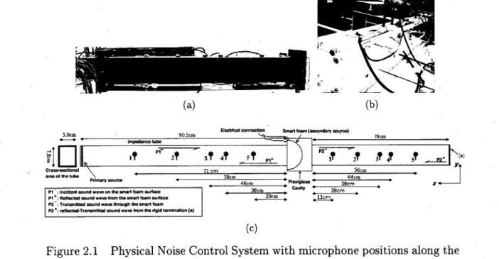
2.1 Physical Noise Control System with microphone positions along the length
of the impedance tubes: (a) Absorption-side waveguide (b)
Transmission-side waveguide (c) Schematic diagram of microphone positions in the
waveg-uides · 15
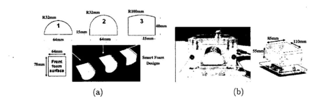
2.2 Smart Foams: (a) Designs of the 3 smart foam prototypes (b) Smart foam
1 inside plexiglass cavity
16
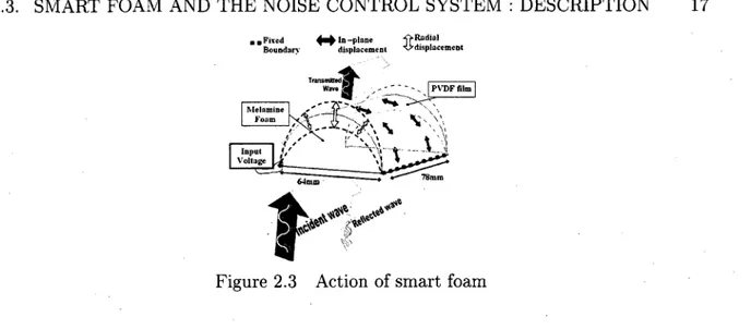
2.3 Action of smart foam 17
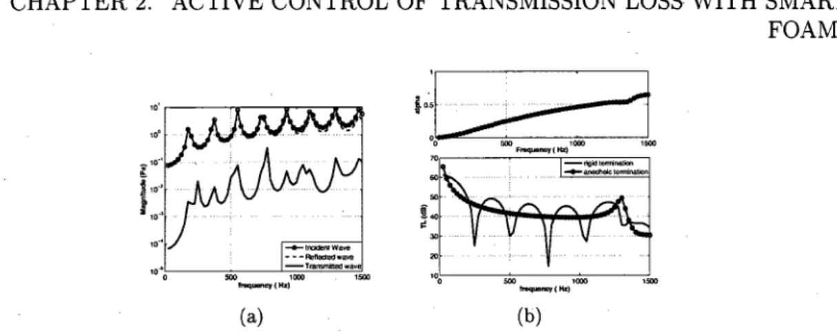
2.4 Response of the noise control system with design 1 of the smart foam
un-der the action of primary source: (a) Amplitude of Incident, Reflected &
Transmitted Pressure waves (b) Absorption coefficient (top) and
Transmis-sion Loss (bottom)
22
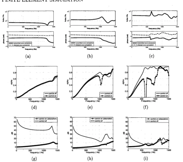
2.5 Optimal active control simulations for the smart foam designs 1, 2 and 3
(left, center and right respectively): (a), (b), (c) show the amplitude and
phase of the control input for transmitted wave cancelation; (d), (e), (f)
show the absorption coefficient for the case of cancelation of transmitted
wave (transmission control); (g), (h), (i) show the TL for the case of
can-celation of reflected wave (absorption control)
23
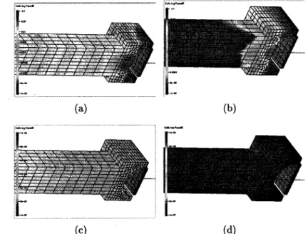
2.6 ("Color online") Squared acoustic pressure field behind the smart foam
be-fore and after cancelation of transmitted pressure: (a) Bebe-fore Control at
1500 Hz (b) After Control at 1500 Hz (c) Before Control at 300 Hz (d)
After Control at 300 Hz 25
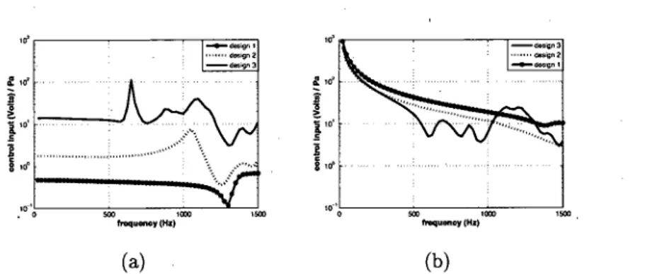
2.7 Comparison of Control Input per unit incident acoustic pressure on the
foam surface: (a) Cancelation of transmitted wave (b) Cancelation of the
reflected wave 27
2.8 Block diagram of Adaptive Feedforward Control and a Schematic Diagram
of the Experimental Active Control System
29
2.9 System response under the action of the primary and secondary sources:
(a) Magnitude of propagative wave components for broadband input of the
primary loudspeaker (b) Optimal control input magnitudes for cancelation
of transmitted and reflected waves, per unit magnitude of the incident wave(c) Absorption coefficient (d) Transmission Loss
32
2.10 Control Filter: (a) Frequency response of the control filter (b) Coherence
between primary source input and error microphone
33
2.11 Active control of transmitted wave magnitude for broadband disturbance:(a) Magnitude of transmitted wave (b) Transmission Loss
34
2.12 Active control results for broadband and single frequency input: (a) Control
input per unit incident wave magnitude (b) Transmission Loss
34
3.1 Physical Noise Control System with microphone positions along the length
of the impedance tubes
44
3.2 Smart foam prototype and the plexiglass cavity 45
3.3 Strain in the PVDF membrane along the circumferential and axial directions 50
3.4 Passive response of the noise control system under the action of primary
source: (a) Absorption Coefficient (b) Transmission Loss
51
3.5 Comparison of radial Volume Velocity cancellation of the PVDF membrane
and transmitted sound wave cancellation: (a) optimum control input (b)
Transmission Loss 52
3.6 PVDF deformation (projected view) for far-field pressure control at 1500
Hz: (a) passive (b) active
53
3.7 Feedforward active control of the transmitted sound wave, or the mechanical
charge response of the PVDF sensoriactuator
54
3.8 (a) Comparison of the numerical and experimental mechanical current
re-sponse of the PVDF film under primary perturbation (b) control input for
minimization of the PVDF mechanical current and its comparison withoptimal TL control input
55
3.9 Control of the PVDF mechanical current response : (a) Mechanical current
response before and after control (b) percentage reduction in the squared
velocity of the center of the PVDF film after control
56
3.10 Block diagram of the absorption control problem
59
3.11 (a) Modified block diagram (b) Virtual error signal block diagram
60
3.12 Virtual error minimization for absorption problem (a) Absorption coefficient(b) Control input (top) and mechanical charge response (bottom) per unit
pascal of the incident acoustic pressure amplitude
62
3.13 Virtual error control for TL problem (a) Transmission loss (b) Control
in-put (top) and mechanical charge response (bottom) per unit pascal of the
LIST OF TABLES
2.1 Geometrical Parameters of the Smart Foam prototypes 36 2.2 Structural and acoustical parameters of the melamine foam 36 2.3 Elastic and electric properties of the PVDF membrane 37
2.4 Elastic properties of the bonding material
37
3.1 Elastic and electric properties of the PVDF membrane 65LIST OF ACRONYMS
A list of acronyms used in the present work. Acronym Definition
TL Transmission Loss
SISO Single Input Single Output MIMO Multiple Input Multiple Output PVDF Polyvinylidene Fluoride
SPL Sound Pressure Level
FIR Finite Impulse Response
IIR Infinite Impulse Response
LMS Least Mean Square
fx-LMS filtered reference Least Mean Square
Cu-Ni Copper-Nickel
d.o.f. degrees of freedom Op. Amp. Operation Amplifier
CMR Common Mode Rejection
CHAPTER 1
INTRODUCTION
1.1
General Remarks
Noise and vibration control, in a wide range of industrial and daily life applications, has
become a field of intense engineering and scientific interest over the past few decades. The
study has been incentivized by environmental considerations, legal compliance, necessityof improving the lifespan of the associated vibrating structures and also due to enhanced
personal comfort consideration and increasing commercial interests.Sound absorbing materials have been in practice for a long time now and they offer the
most practical and economic solution in many situations. Generally, all materials have
some sound absorbing properties over particular range of frequencies which maybe
de-scribed by calculating the sound absorption coefficient of these materials. It is possible to
classify the sound absorbing material into three broad categories - (a) Porous Absorbers
(e.g. fibrous mineral wool, glass fiber, aerated plaster, spray applied cellulose, etc., these
are the most commonly used and are efficient in the mid and high frequency range of
incident sound, the thickness of these materials have a strong bearing on their soundab-sorption coefficient), (b) Panel Absorbers (non-rigid non-porous membranes like thin wood
paneling over framing, lightweight impervious ceilings and floors etc. which are capable of
exhibiting resonance characteristics in response to the excitation sound field, and are most
efficient in the low frequency range) and (c) Resonators (some perforated materials and
other materials which have openings as a combination of holes and slots, like Helmholtzresonators, and these typically act to absorb sound in a narrow frequency range; also, the
resonant frequency is governed by the geometrical dimension of the resonators).
On the other hand, a wide range of active control strategies can also be developed that
enables cancellation of a primary sound source by the use of a secondary source and anerror microphone. The underlying physical principle is that of interference. The
coeffi-cients of the digital filter, that will typically drive the secondary source based on some
reference signal correlated to the disturbing noise, are chosen to ensure that the
wave-form of the sound radiated from the secondary source is aligned in time in order to be(as far as possible) opposite to the waveform produced at the error microphone by the
primary source. However, most of the acoustic waveforms of practical interest are highly
unpredictable (like those inside an automobile due to the airflow past the passenger cabin
and the vibrations generated by the contact of the tires with the road) and in addition,
there may be multiple primary sources of such unwanted sound. In such cases it becomes
more difficult to find reference signals that give a prior indication of the acoustic pressure fluctuations well before their arrival. Also, global control strategies have proved to be less efficient compared to local control ones.However, the idea of improving the overall absorption coefficient of the passive materials
over a broad range of frequencies have motivated researchers to combine active components
with the conventional passive methods and thus utilizing the complementary strengths
of these individual components in developing efficient control strategies and algorithms that can actually reduce the dimensional penalty one has to incur while using the passivecomponents alone (especially at low frequencies). It is also worth mentioning that although
many of the physical principles involved in active sound control have long been established,
the development of considerably fast and sophisticated digital processors over the past few
decades has stimulated the growth and rapid enhancement of the study of active noise
control.
Smart foam, is a composite noise control treatment consisting of a layer of partially
retic-ulated passive acoustic foam material with a distributed piezoelectric actuator, such as
polyvinylidene fluoride (PVDF) embedded in it. The passive foam offers good sound
at-tenuation in the mid and high frequency ranges, while the active piezo-actuator provides
a solution for low frequency noise cancellation with the help of active control. Thus the resultant smart foam combines the inherent mid to high frequency passive noise controlcapability of an acoustical foam treatment with low frequency noise control capabilities of
an active control system, and hence implementing the passive sound proofing system as
part of the active system to conserve weight and space.1.1.1 Literature Review: Smart Foam
Acoustic waves incident on the porous material are dissipated due to structural, viscous and thermal losses due to the relative motion of the solid and fluid phases of the foam
matrix. However, the inefficiency of these materials to exhibit satisfactory low frequency
absorption coupled with the increasing dimensions at these frequencies have motivated
the development of smart foams. Low frequency attenuation may be achieved using an
appropriate control input applied to the curved layer of the active piezo-material. This
active material, when strained under the application of an external electrical voltage, will
induce a volume velocity by means of a pumping action. This pumping action normally
1.1. GENERALREMARKS 3
results due to the curvature of the distributed actuator which leads to a strong coupling
between the in-plane displacement of the active material with the radial out-of-plane
displacement. This leads to an operation similar to that of an ordinary loudspeaker,
which generates a secondary sound field under appropriate control input.
Thus the 'Smart foams' or 'Adaptive Foams' present a new approach in controlling
un-wanted noise field and presents manifold advantages over other passive/active noise control
solutions. Fuller et al [Guigou and Fuller, 1998; Fuller et al., 1996, 1994] have conducted
studies on smart foam and demonstrated their effectiveness in sound control applications
and the advantages they present over the other hybrid passive/active systems. The
con-figuration of the smart used in their study [Fuller et al., 1994] consisted of cylindrically
curved section of PVDF film embedded in partially reticulated polyurethane acoustic foam with an active input to the PVDF element which was driven by an oscillating electricalinput. Their study of radiation control was implemented in two steps - first, with a
far-field traverse microphone which fed an error signal into the single channel filtered-x LMS
control algorithm along with a reference signal from the disturbance, and secondly with
a PVDF sensor mounted on the surface of the adaptive foam whose response is used asthe error signal to be minimized. A global sound attenuation of approximately 20 dB
was achieved with the far-field microphone as the error sensor, while the PVDF film errorsensing strategy exhibited no far-field pressure reduction at all. The reflection control
ex-periment was conducted with plane acoustic waves incident on a smart foam placed at one
end of a standing wave tube and with two microphones used for estimating the reflected
wave intensity using an analog wave deconvolution circuit. The control was accomplished
with a fx-LMS algorithm. The reflection control can be interpreted as a process of actively
creating an impedance on the surface of the foam (using the embedded PVDF actuator)
which matches the impedance seen by the incident plane wave propagating away from the
source. Up to 40 dB of attenuation of the reflected wave was achieved at frequencies above
600 Hz while using the active control strategy. At low frequencies between 150 and 300
Hz, the adaptive foam was less efficient but still produced a 10 dB reduction in the SPL.
Further development was brought about in 1996 [Fuller et al, 1996], which was devoted
to the development and testing of foam-PVDF smart skin for use in aircraft fuselage in
order to reduce interior noise associated with the turbulent boundary layer excitation. Animprovement in the radiation efficiency of the smart foam was brought about in the paper
using the idea of Tibbets [Tibbetts, 1977] and the improved PVDF actuator configuration
- Leoój w slecir&l-ts
PtT)F andato*
Figure 1.1 PVDF actuator configuration in Parallel [Fuller et ai, 1996]
In this improved configuration, the continuous PVDF film was divided into several individ-ual transducers by a chemical etching process. Thus effectively the actuator is composed of several individual transducers connected in parallel which are driven in the opposite directions simultaneously. This results in a higher sound radiation efficiency compared to the previous approaches. This configuration gives global cancellation of harmonic and broadband noise induced by a vibrating piston and it was possible to control SPLs of the
order of 60 dB at 300 Hz when applying a maximum allowable voltage (300 Vrms). In
order to further improve the radiation efficiency of the system in the low frequency range, to develop more integrated error sensors for compact design and to develop an adaptivefeedback controller to avoid the use of a reference signal (necessary in feedforward control),
Guigou and Fuller [Guigou and Fuller, 1998] compared the performance of the radiation
control smart foam using both the feedforward and the feedback controllers for different disturbance frequency bandwidths. The error signal was provided in both cases by aner-ror microphone located in close proximity of the smart foam. Better results were obtained
for the case of adaptive feedback control which is quite expected since the reference signal has to be synthesized. However, for greater frequency bandwidths, the results deterioratesuggesting that an adaptive feedforward controller is more efficient in reducing radiated
power over broad frequency bandwidth.Mathur et al [Mathur et al., 2001] have developed a finite element model to meet the design
requirements of the smart foams. A 3D model was made for the fluid and the poroelastic
domain, while the PVDF film was modeled in 2D. The active control implementation was made in a 2D representation. The experimental validation of their model for thesimple cases showed the effectiveness of their model. A number of near field and far
field microphones were used for control and measurement, and accelerometers responses mounted on the test panels provided the realistic reference signal. The noise reduction results due to different active control strategies on the test panel and the fuselage sectionof Boeing 757 demonstrates significant improvement under both acoustic and structural
1.1. GENERAL REMARKS 5
excitations. The strategy using the far-field minimization was observed to give better results with a reduction of about 7-10 dB in a the frequency band of 200-700 Hz. However, the piezoelectric actuator model was limited to 2D.
A 2D smart foam model was considered in the works of Chin et al [Chin et al, 2002] to
demonstrate the active control implementation. The arrangement consisted of three smart foam prototypes placed at the termination of an air duct and excited by a line volumevelocity (primary source) which represents a noise of 80 dB SPL. Both thé global (total
acoustic pressure vector set to zero, which in effect aims at minimizing the noise field atevery point inside the tube) and local (aims at minimizing the acoustic pressure at certain
preselected locations in the tube) noise reduction strategies have been investigated in the
paper. The overall reduction ranges from 10 to 40 dB. The local control strategy proved to be more effective than global control, because fewer number of pressure variables had to be minimized for this case. Also, the smart foam placed at the center in the array of the three foams, proved to be more critical in reducing the sound pressure than the other two, and this can be utilized as an advantage in the subsequent control strategy designs.D'Angelo [D'Angelo, 2004] continued in the line of Fuller and studied the influence of
reference sensor and sensor error on the effectiveness of noise control in an airplane cabin.
He managed to get attenuations of 16dB on the frequency range 400-800Hz with a
config-uration of 3 reference sensors and a near field error sensor.
The use of smart foam has also been applied to the control of noise induced by the
turbulent boundary layer (TBL) inside the aircraft fuselage in the work of Griffin [Griffin,
2006]. An fx-LMS algorithm was used for the tests. Control was applied at one bay
using an arrangement of six smart foam elements configured for a four channel control.
Each channel of control had a single accelerometer for providing the reference signal with four microphones, placed 20 inches from the plate, which acted as the error sensors. A reduction of 2 to 5 dB over a control bandwidth of 400-1000 Hz was attained with anaverage attenuation of 2.5 dB. Passive attenuation achieved by the presence of the foam
alone was 3.8 dB over 400-1000 Hz.
Leroy et al [Leroy et al, 2007] presented a finite element study of three smart foam
prototypes with different designs of the distributed piezoelectric actuators. The prototypes
were placed inside impedance tube and the assumption of plane wave propagation was assumed to hold true over the entire frequency range of interest from 100 to 1500 Hz. The melamine foam material used as the passive sound absorbent material offers the advantageof being light weight. The best passive behavior for acoustic absorption was obtained with
the third configuration (having the highest actuator area). Real time adaptive control
was implemented using the fx-LMS algorithm, a unidirectional microphone as the error sensor, and the primary source input as the reference signal. The control results show good improvement in absorption coefficient over the frequency range of interest. For harmonic primary perturbation, a perfect absorption coefficient of 1 is obtained at all frequenciesfor all the three prototypes, while for the adaptive control of white noise (broadband
noise), their performance deteriorates. This deterioration has been attributed primarily
to the causality constraint of the active noise control system, and also to the possible non-linear effects of the smart foam prototype. The results show that prototype 3 combinesthe passive/active characteristics of the smart foam quite well and gives an absorption
coefficient close to 0.9 from 300 to 1500 Hz.
1.1.2
Main Objectives
The literature review reveals that there have already been some developments in the design of smart foams for absorption and radiation control. However the acoustic transmission control problem with smart foams, still remains a sparsely studied domain, and forms the prime focus of the current work. The main objective of the current work is to enhance the acoustic transmission loss of the passive foam material using the smart foam principle,
and to gain an in-depth understanding of the physical mechanism that leads to the above
goal.A complete 3D finite element model of the poroelastic material with the active component
integrated to it has been developed at the GAUS laboratory which enables the investigation
of the various performance parameters of the smart foam that may prove to be importantin terms of their noise attenuation capabilities [Leroy, 2008]. The specific areas of interest
of the present study maybe listed as follows.- Study of sound transmission loss of the Smart Foam
The energy indicator selected as the optimization parameter for this problem is
transmis-sion loss (TL), which is defined as the ratio of the incident sound power to the transmitted
power [Galland et al, 2005]. The present problem is restricted to the study of plane wave
propagation in impedance tube, however, the TL energy indicator is equally valid for the
general case of diffused field excitation problems. It will be interesting to study the
trans-mission efficiency of these systems under the passive/active operating conditions, where
the finite thickness smart foams used for sound absorption purposes can be investigated for the amount of acoustic energy transmitted through them under passive operatingcon-1.1. GENERAL REMARKS 7
ditions. This will basically reflect the transparency of the smart foam systems to the incident sound waves. The modification of the PVDF vibration response, under optimal control, that will result in the cancellation of propagating transmitted sound wave will taken up in detail in the present study. For the absorption control problem, the actua-tor modifies the surface impedance of the smart foam materials such that the absorption coefficient is enhanced. A comparative study of the absorption problem of with that of transmission control will be considered here which can highlight the complimentary na-ture of these problems and help to improve the performance of the active noise control system and identify the key design parameters associated with smart foams. It will also
be interesting to look into the reflected wave characteristics as the smart foam system is
optimized for the transmission loss problem. It does not necessarily hold thatmaximiz-ing the transmission loss will enhance the acoustic absorption, and hence remains to be
investigated.- Understanding the physical mechanisms of energy dissipation in smart foam The finite element model developed at GAUS is an analysis tool that is capable of providing
the information about location and extent of various modes of energy dissipation (like
viscous, thermal and structural) in the smart foam prototype. These indicators can allow
us to understand better the physical mechanisms of energy dissipation, which will help torecognize the ways to increase the overall absorption of the material. Based on these, it
may be possible to put forward important recommendations on the key design parameters.
Also comprehensive literatures are available on the models that characterize the behavior of
different poroelastic materials, with varying physical properties (using complex impedance
and complex wave number expressions) . However, the final expressions obtained are often
complicated and throws little light on important physical and geometrical parameters that
can influence the dissipation phenomenon to the greatest extent. The study of the acousticenergy indicators with the FEM model can provide valuable insight into this aspect and
help to identify the key optimization methods.- Sensors
The design and position of sensors is always an important consideration in smart foam
configurations owing to the requirement of efficient control- algorithm and compactness of
the system. It can be seen from the above literature survey that the position of sensors in
the acoustic field is critical to the performance of the active control system, it is desirable that the sensors are located close to the smart foam prototypes. However, the acoustic nearfield may pose significant problems in this implementation. Unidirectional microphones
are generally used for the purpose of sensing the acoustic pressure which serves as the
reference signal as well as the error signal in the absorption control experiments inside the impedance tube. It will be interesting to investigate the possibility of deriving the controlerror signals from the vibratory response of the smart foam itself. This can potentially
improve the efficiency of the control algorithms and make way for a compact design of the
smart foam system. - Control Strategy
The final objective would be to establish the active control strategy that can be used with the transmission control application. The real-time control of optimizing the absorption coefficient of smart foams have been done using the fx-LMS algorithm. It remains to be seen if this methodology can perform with equal efficiency in the TL control application. Also, the use of alternate error sensors in the active control strategy may require a mod-ification in the control algorithm which will also form a part of the present study. The
efficiency of these active control algorithms has to be tested and optimized in real-time
scenarios while minimizing the unwanted sound field.1.1.3 Outline of the Thesis
The thesis is organized as follows. All the work has been compiled and put together in two
articles which have been submitted to their respective journals (Journal of the Acoustical
Society of America and Journal of Intelligent Material Systems and Structures). Here,
the two articles have been reproduced in their entirety and contain the details of themethodology and results obtained during the course of the present research work.
The literature review on the application of smart foams in active noise control applica-tions has been presented in section 1.1.1 which gives a background of the technological innovations that have been directed in this domain and helps to put the present work in context of the broader research perspective. The main objectives of the present masters research have been detailed in section 1.1.3.
Chapter 2 presents the first part of the thesis, which is in the form of an article that has
been submitted to the Journal of the Acoustical Society of America. This part contains
the details on the study of transmission loss with smart foams and the use of feedforward
control to optimize the passive TL under broadband and tonal primary perturbation. The
description of the finite element method used in the numerical simulations and the details
of the physical noise control system has been presented in this work. The comparison of
the simulation and experimental results throws significant light on the physical mechanism1.1. GENERAL REMARKS 9
of noise cancellation of the active noise control system, and the efficiency of the control
mechanism along with the deviation of the physical system from the idealized simulation
model has been studied in detail.
Chapter 3 contains the second part of this body of work and has been reproduced from
a manuscript that has been submitted to the Journal of Intelligent Material Systems &
Structures. It contains the details of the principle and methodology of implementationof a piezoelectric sensoriactuator that can be utilized as an error sensor in the active
control technology in order to increase the compactness and efficiency of the noise control
system compared to the use of far-field pressure sensors. The motivation of this innovation
has been provided by the numerical simulations of the TL control problem which gives
satisfactory improvement of the TL (in low and mid frequencies) under optimal control of
the radial volume velocity of the continuous spatially distributed piezo-actuator embedded in the smart foam. Also, a virtual error control strategy has been realized with thepiezoelectric sensoriactuators which helps to utilize the latter technology with both the
absorption and transmission control problems. The results show satisfactory performance
of this technique for both these optimization problems. However, some limitations in theperformance of the control system over specific frequency bandwidths have been observed
which have been reported in the article along with possible explanations for their under-performance.Chapter 4 gives the general conclusions of the present work along with a summary of
prin-cipal results that have been obtained from the finite element simulations and experimental
active control studies. Based on these conclusions, the direction of future research in the domain of active noise control with smart foam technology, as foreseen by the author, has been enunciated briefly.CHAPTER 2
Active Control of Transmission Loss with Smart
Foams
Avant- propos
Authors :
A. Kundu : étudiant en maîtrise, Université de Sherbrooke, Faculté de génie,
Départe-ment de génie mécanique.
A. Berry : professeur, Université de Sherbrooke, Faculté de génie, Département de génie
mécanique.
Date of Submission : 24 March 2010
Journal : Journal of the Acoustical Society of America Manuscript Number : MS 10-08786
Status : under review
Titre français : Contrôle actif de transmission loss à l'aide de mousses actives Contribution of the document :
This paper presents the numerical simulation results of the transmission control problem along with the experimental study of the real-time feedforward control. The experimental results have been compared with the numerical simulation results and the mechanism of cancellation of the transmitted sound pressure is explained .in light of the modification of the vibration response of the piezo-actuator of the smart foam. Thus the study forms
an important and integral part of the present work and demonstrates applicability of the
concept of smart foams to transmission control problems.Résumé français :
Les mousses actives combinent les avantages complémentaires de matériaux en mousse pas-sifs et d'un actionneur piézoélectrique spatialement distribué et intégré dans la mousse,
pour des applications de contrôle actif du bruit. Dans ce document, le problème de
l'amélioration de l'indice d'affaiblissement des mousses actives, en utilisant des stratégies de contrôle actif, a été étudié à la fois numériquement et expérimentalement. L'expérience s'est déroulée à l'intérieur d'un guide d'onde sous la condition de propagation en ondesplanes. La simulation par éléments finis d'un système de contrôle de bruit couplé a été
en-treprise avec trois conceptions différentes de mousse active, et leur efficacité pour annuler
12 FOAMS l'onde transmise en aval de la mousse active a été étudiée. Les résultats des simulations permettent de mieux comprendre le phénomène physique de l'annulation active du bruit et explique l'impact de la conception de mousse active sur les résultats du contrôle actif optimal. Des études expérimentales visant à mettre en œuvre le contrôle en temps réel pour l'optimisation de l'indice d'affaiblissement ont été effectuées en utilisant l'algorithme classique des moindres carrés. Les résultats de contrôle actif en large bande sous une source monofréquentielle démontrent une bonne amélioration de l'indice d'affaiblissement
des mousses actives. L'étude donne une description comparative des problèmes de
con-trôle de la transmission et de l'absorption à la lumière de la modification de la réponse vibratoire de l'actionneur piézo-électrique sous contrôle actif.
2.1
Abstract
Smart foams combine the complementary advantages of passive foam material and spa-tially distributed piezoelectric actuator embedded in it for active noise control applications. In this paper, the problem of improving the transmission loss of smart foams using ac-tive control strategies has been investigated both numerically and experimentally inside
a waveguide under the condition of plane wave propagation. The finite element
simu-lation of a coupled noise control system has been undertaken with three different smartfoam designs and their effectiveness in canceling the transmitted wave downstream of the
smart foam has been studied. The simulation results provide insight into the physical phenomenon of active noise cancellation and explain the impact of the smart foam designs on the optimal active control results. Experimental studies aimed at implementing the real-time control for transmission loss optimization have been performed using theclassi-cal single input/single output filtered reference Least Mean Square algorithm. The active
control results with broadband and single-frequency primary source inputs demonstrate agood improvement in the transmission loss of the smart foams. The study gives a
com-parative description of the transmission and absorption control problems in light of the
modification of the vibration response of the piezoelectric actuator under active control.2.2
Introduction
The smart foam advantageously combines the inherent mid to high frequency passive noise control capability of an acoustical foam treatment with the low frequency noise control
capabilities of an active control system, and hence implementing the passive sound proofing
2.2. INTRODUCTION 13
system as part of the active system to conserve weight and space [Guigou and Fuller, 1998].
Some of the hybrid passive-active approaches with foam materials for absorption control have been tested in the works of previous researchers using a strategy of imposing a 'zeropressure' on the back of the porous material[Furstoss et al, 1997; Galland et al, 2005]
or 'impedance matching' of the active surface of the hybrid noise control system [Cobo
et al, 2003, 2004; Yuan, 2003]. They mostly used a secondary loudspeaker which acted as
an active area behind a passive sound absorbent layer (e.g. micro-perforated absorbent,
porous layer, etc.) with an error microphone, placed just behind the absorbent layer,
to obtain the desired acoustic performance. Both these strategies, though effective in a broad frequency range, incurs a weight and space penalty that is undesirable in compactaerospace applications.
An alternate control strategy to this hybrid passive-active approach is offered by smart foams which integrate a distributed piezoelectric actuator into the passive sound absorbent material. The passive material performs satisfactorily at high frequencies in terms of at-tenuation of the incident noise, while the active actuator takes over in the low frequencies, where the efficiency of the passive layer is limited by the impractical space and weight re-quirements. The use of smart foams in acoustic radiation control problems has shown good
noise control effectiveness over specified frequency bandwidths [Fuller et al, 1996, 1994]
in very thin and compact arrangements. Recent acoustic absorption control experimentsundertaken with smart foams[Leroy et al, 2009b; Leroy, 2008] show their effectiveness in
enhancing the broadband absorption coefficient for normally incident plane waves. The acoustic transmission control problem with smart foams, however, still remains a sparsely studied domain, and is the prime focus of the current work.The main objective of the current work is to enhance the acoustic Transmission Loss
(TL) of a passive foam material using the smart foam principle, and to gain an in-depth
understanding of the physical mechanism that leads to the above goal. In this paper the
passive/active behavior of a smart foam is presented with the assumption of an acoustic
plane wave incident normally on the smart foam, and it is partially transmitted to the other side of the smart foam. The smart foam design, in the present study, consists of a passive melamine foam material which is covered on its rear surface by a curved piezoelectricpolyvinylidene fluoride (PVDF) membrane, which acts as the control actuator. The PVDF
creates an acoustic insulation between the incident and transmitted sides of the smart
foam, and this results in a high passive TL. For the case of active transmission control, the TL is enhanced further due to the vibration restructuring of the smart foam system,
14 FOAMS and it results in a part of the incident acoustic energy being absorbed by the active PVDF
membrane.
The outline of this paper is as follows. Sections 2.3.1 and 2.3.2 give a detailed description of the physical noise control system and the design of the smart foam prototypes used in the present study. Section 2.3.3 details the methods and equations used for evaluating
the propagating wave components and the optimal control input. This is followed by the
Finite Element simulation of the entire noise control system in Section 2.4. A completefinite element model of the poroelastic, piezoelectric, acoustic and elastic domains[Leroy
et al. , 2009a] has been used to simulate the system response at each frequency for harmonic
excitations of the primary and secondary sources. Section 2.4.1 includes the description of the modeling aspects of the smart foam prototypes and the noise control system as a whole, while section 2.4.2 gives a thorough description of the numerical simulation results. An in-depth analysis of the behavior of the noise control system is also presented here. Following this, section 2.5 describes the experimental implementation of the real-time control of TL using digital signal processors. The TL control is implemented withsingle-input-single-output (SISO) adaptive feedforward controllers using the filtered-reference
least mean square (Fx-LMS) algorithm with a unidirectional microphone providing the
error signal. A brief description of the theory and methodology of feedforward control
used for our noise control system is given in section 2.5.1. The behavior of the passive noise control system and the case of experimental active transmission control are detailed in section 2.5.2, along with the discussions related to the effectiveness and limitation ofthe control methodology.
2.3
Smart Foam and the Noise Control System :
De-scription
2.3.1
Experimental Setup
The details of the smart foam and the physical noise control system used to implement the active TL control are described in this section. The smart foam is located inside a
plexiglass cavity which has impedance tubes attached on both of its sides. The study is
restricted the case of plane wave propagation in the impedance tubes.The noise control system used in the present study is shown in Fig. 2.1. The incidence and transmission side impedance tubes on either side of the smart foam inside the plexiglass
2.3. SMART FOAM AND THE NOISE CONTROL SYSTEM : DESCRIPTION 15
cavity are shown in Figs. 2.1(a) and 2.1(b). The primary source comprises of two speakers
placed face to face of each other at one end of the tube and perpendicular to the tube axis. Electret microphones, placed along the length of the impedance tubes, are utilized to evaluate the propagating wave amplitudes and hence record the efficiency of control. A complete description of the physical noise control set-up and the inter-microphone spacingson the incidence and transmission side waveguides are shown schematically in Fig. 2.1(c).
The transmission side waveguide behind the plexiglass cavity ends in a rigid termination.(a) (b)
Electrical connection
Ol
Cross-sectional
area of the tube
it St 4Î
Smart foam (secondary source)
9 at St f 9
Primary source
P1 ~: Incident sound wave on the smart foam surface
P1 + : Reflected sound wave from the smart foam surface P2~ : Transmitted sound wave through the smart foam P2 +: reflected-Transmitted sound wave from the rigid termination (a)
Plexiglass *~
~* Cavity
*"-(e)
Figure 2.1 Physical Noise Control System with microphone positions along the
length of the impedance tubes: (a) Absorption-side waveguide (b)
Transmission-side waveguide (c) Schematic diagram of microphone positions in the waveguides
The different propagating wave components have been indicated in Fig. 2.1(c) which are .
evaluated with the help of microphone pairs using the classical two-microphone method[ASTM-E1050-98, 1998]. Also, a unidirectional electret microphone, which is utilized to
provide the error signal for the implementation of real time control, is placed inside the
transmission side waveguide at a distance of 45 cm from its right end rigid termination(shown later in Fig. 2.8). This microphone faces the smart foam and is used to detect the
transmitted sound wave.
The high frequency limit of the problem is restricted to well below the higher mode
cut-off frequency of the impedance tubes (which is roughly around 2200 Hz for our present
case) to ensure plane wave propagation inside the tube. The different inter-microphone
spacings ensure an accurate estimate of the propagating wave amplitudes at all frequencies
(discussed in more detail in Section 2.5.1). It is ideally assumed that there is no other
16 FOAMS acoustic transmission path between the incidence and transmission side waveguides other than through the smart foam. However, this assumption is not quite accurate for the actual physical noise control system assembly, as can be seen in the experimental results
at low frequency.
2.3.2
Smart Foam Description
The smart foams used in our study are a composite noise control treatment consisting of a distributed PVDF actuator, attached on a layer of Melamine foam. Three different designs of smart foam with varying volume and actuator designs have been used in our
study, as shown in Fig. 2.2(a) (refer to Table 2.1 for the geometric details of the individual
prototypes). The first prototype, for example, is a half cylinder of foam with its curved
rear surface covered with a PVDF film actuator. Since, melamine is highly porous, its surface is conditioned with a heat-reactivatable membrane and the PVDF is bonded ontoit using a double-side tape. The bottom rectangular face of the smart foam is exposed to
the normal plane acoustic waves.
R32mm RlOOmm
?>
R32mm 40p?p? 15mm I 15 mm 85mm 64mm 64mm 110mm ^;SS
^ 64mmX,
Smart Foam Front Designs 78 mm toam suifa» (a) (b)Figure 2.2 Smart Foams: (a) Designs of the 3 smart foam prototypes (b) Smart
foam 1 inside plexiglass cavityIt is observed in subsequent sections that the different foam volumes and actuator designs of the three smart foam prototypes have a significant impact on the passive absorption and
TL of the system. The varying PVDF film area and curvature markedly modify the sound
radiation efficiency of the individual smart foams, and hence their control authority. The thickness of the PVDF membrane for all the three designs is 28 microns, and it possesses Cu-Ni surface electrodes. The smart foam system is mounted inside the plexiglass cavityequipped with electric connections which are used to drive the PVDF actuator, as shown
in Fig. 2.2(b) (with the first prototype). Plexiglass flanges are placed on the lateral sides
of the foam so as to ensure proper support conditions and tightness with the rear cavity.2.3. SMART FOAM AND THE NOISE CONTROL SYSTEM : DESCRIPTION 17 « ,Fixed 4"? In-Plane j>Radial
Boundary displacement ^displacement
Melamine Foam
V oltage
78mm 64mm
Figure 2.3 Action of smart foam
Fig. 2.3 shows the pumping action of the PVDF membrane of the first smart foam design,
which is the fundamental mode of vibration of the PVDF in response to the acoustic waves and external electrical excitation. The curved shape of the PVDF membrane enables a
strong coupling of the in-plane displacement components with the out-of-plane
displace-ment. Since we assume an ideal condition of no acoustic leakage or flanking transmission paths between the incidence and transmission side waveguides, the transmitted sound pressure is solely a function of the vibro-acoustic response of the PVDF membrane, and the passive TL offered by the smart foams is quite high, especially at low frequencies. The absorption coefficient is also dependent on the vibration response of the PVDF membrane in addition to the passive dissipation in the foam material, which is seen in the numerical control results. Also, it should be mentioned that since the smart foams are placed insidethe plexiglass cavity-waveguide assembly, its far-field radiation is significantly different
from what it would have been in free field.
2.3.3
Absorption and Transmission Loss measurements
The complex propagating wave amplitudes have been derived using the Chung and Blaser
method [Chung and Blaser, 1980], and the ASTM E1050 standard method
[ASTM-E1050-98, 1998] with the several microphone pairs placed along the length of the tube and under
the assumption of plane wave propagation. The different propagating wave amplitudes
(incident P^, reflected P1+, transmitted P2- and reflected-transmitted P2+ as shown in
Fig. 2.1(c)) are calculated using the classical expressions for plane wave components
trav-eling in the positive z-direction, P+ (the reflected and reflected-transmitted wave
am-plitudes, Eq. (2.Ia)) and negative z-direction, P- (the incident and transmitted wave
18 FOAMS
amplitudes, Eq. (2.Ib)) as follows :
? ? „—ikd
P+ = "
?*
eikL™,
(2.1a)
_ ? ? „¿fed
P- = "
?f,se~'fcLm·
(2.1b)
-2isin(fcd)
v
'
where the variables in Eqn. (2.1) are defined as follows: P7n and Pn are the complex values
of pressure at the microphones placed at points m and ? along the waveguide (maybe on
either side of the smart foam) with point m situated further away from the origin in the
positive ¿-direction than n, d is the distance between points m and n, k is the wavenumber and L7n is the distance of point m from the origin.The 'offline' estimation of the optimal control input required to cancel a desired propagat-ing pressure wave component is obtained utilizpropagat-ing the principle of superposition. Firstly, the system response under the action of the primary and secondary source inputs are
evaluated separately. And then the optimal complex secondary source input, ß+ or ß~,
required to cancel the reflected sound wave (propagating in the positive ¿-direction) or
the transmitted sound waves (propagating in the negative z-direction) respectively, are
calculated using the following expression :ß± = _ npnm
TJ ? _ p^fzkdwhere Hpnm and Hsnm are the transfer functions between microphone pairs under the
action of the primary and secondary sources respectively and are expressed as Hnm = ¦&-.
The calculated ß± is a non-dimensional quantity which is normalized with the incident
pressure amplitude to obtain the desired control voltage input per Pascal of the incidentpressure. All these expressions are valid for the e+lwt time convention.
The acoustic energy indicators that have been monitored during the course of this
op-timization of control input are the absorption coefficient (a) and the Transmission Loss
(TL) which are defined as in Eqns. 2.3:
p+2
2.4. FINITE ELEMENT SIMULATION 19
TL = 10logw
(2.3b)
where P1-, P1+ and P2" are again the complex amplitudes of the propagating incident,
reflected and transmitted pressure waves respectively. These energy indicators are key parameters in defining the performance of the noise control system and determining the efficiency of control.2.4
Finite Element Simulation
This study comprises of a detailed finite element study of the response of the entire noise control system under primary and secondary source perturbations. We consider three
different designs of the smart foam for the numerical simulations (as shown in Fig. 2.2(a))
and study their effectiveness in terms of the active and passive TL values and the actuator control authority. The simulations of the complete noise control system have been done with harmonic primary and secondary source disturbances introduced into the system over a bandwidth of 25 - 1500 Hz in steps of 25 Hz. The simulation gives the frequencydomain response of all the degrees of freedom (d.o.f.) associated with each of node of
the complete system. The amplitude and phase is obtained relative to the perturbationintroduced into the system (either the primary source piston volume displacement, or
the secondary source PVDF voltage input). These frequency domain data are utilized to
calculate the acoustic energy indicators and the optimal control input required to minimizethe desired propagating wave components.
2.4.1 The Finite Element Model
A 3-D finite element modeling of the complete noise control system shown in Fig. 2.1
(including acoustic, elastic, piezoelectric and poroelastic domains) is described here. It
has been utilized in the present study to perform the numerical simulation of the entire noise control system. The finite element model for the poroelastic medium is based onan exact (u,p) formulation of the poroelastic domain [Atalia et al., 2001; Debergue et ai,
1999]. The modeling utilizes quadratic poroelastic, elastic, fluid and piezoelectric elements
to implement the weak integral formulation of these different media involved in the problem
along with the associated coupling and boundary conditions [Leroy et al., 2009a; Leroy,
2008]. The individual elements involved in the modeling of the system are as follows :
1. The poroelastic domain for the foam material has been modeled with 20 noded
brick elements based on an orthotropic definition of the solid phase, and they have20 FOAMS 4 degrees of freedom associated with each node : 3 orthogonal translations and 1 pressure, which results in 80 degrees of freedom per element.
2. The acoustic domain comprises of the 20 noded classical fluid elements with one
degree of freedom (pressure) per node.
3. We have used two kinds of elastic elements in the model viz (i) 20-noded
classi-cal brick elements with 3 translational degrees of freedom per node to model the 3-dimensional waveguide terminations on the left and right of the incidence and transmission side impedance tubes respectively, so as to suppress their modal vi-brations, restricting them to execute rigid body motion only, and (ii) 8-noded plate elements with 6 degrees of freedom per node (3 translations and 3 rotations) to model the elastic bonding layer between the poroelastic foam and the piezoelectricdomain.
4. Surface piezoelectric elements comprising of 8 nodes with 7 degrees of freedom per
node (3 translations, 3 rotations and 1 electrical potential) to model the PVDF
actuator.
5. Lastly, the fluid-structure coupling [Debergue et al., 1999] was implemented with
8-noded surface elements to account for the acoustic-poroelastic, acoustic-piezoelectric,
poroelastic-piezoelectric and acoustic-elastic interface conditions.
We have used two different boundary conditions in our model : (i) fixed displacement
and (ii) fixed electrical potential to introduce forcing terms into the system. The primary loudspeaker has been modeled with a fixed harmonic displacement imposed on all thenodes of the left waveguide termination on Fig. 2.1(c) over the entire frequency range,
while the electrical excitation imposed on the PVDF membrane has been modeled with a fixed harmonic electric potential imposed on the piezoelectric domain. The boundary conditions imposed on the PVDF membrane are of particular importance to the radiation efficiency of the smart foams, since they significantly modify the relative structural modal contributions in its vibration response. The curved edges of the PVDF membrane haveall their nodal translational d.o.f. blocked while the straight edges (coinciding with the
two opposite rectangular edges of the bottom surface of the foam as in Fig. 2.3) have
all (both their translational and rotational) d.o.f. fixed to zero. The acoustic domain is
assumed to be inside a perfectly rigid structure (the impedance tube and the plexiglass
cavity) and therefore, the acoustic pressure gradient normal to the rigid walls has been
set to zero. There is no pressure continuity between the acoustic elements on the incident and transmission sides of the waveguide, thus the transmitted sound pressure is solely a function of the vibratory response of the PVDF membrane which forms an impervious membrane on the rear side of the foam surface.2.4. FINITE ELEMENT SIMULATION 21
Previous measurement of the elastic and acoustic properties of the melamine foam has
revealed that the foam material is anisotropic [Leroy et al, 2009b]. However, for the
present case of numerical simulations, the anisotropic effects are considered for the elastic parameters only, while the acoustical parameters are taken to behave isotropically. The property values of the melamine foam are listed in Table 2.2. The elastic and piezoelectric property values of the PVDF membrane have been incorporated from published data[Bailo et ai, 2003] (Table 2.3). It is to be noted that the higher of the two piezoelectric
strain constants i.e. e^ has been used along the circumferential direction of the PVDF membrane to facilitate a larger electromechanical coupling along this direction, which helps in enhanced vibration response and radiation efficiency of the PVDF actuator per unit input of the electrical voltage. The material property values of the elastic bonding material between the PVDF membrane and the passive foam material that has been usedin the simulations are listed in Table 2.4 (using published data [Leroy et ai, 2009a]). The
finite element model assumes no acoustical leakage or flanking paths between the incidence and transmission sides of the smart foam across the plexiglass cavity.The extremely small thickness of the PVDF membrane could have led to enormous cal-culation time and memory requirements, however, in light of the added stiffness of the bonding layer and the foam, a manageable element size of has been found to be acceptable according to convergence analysis. Higher mesh density is used in the acoustic domain in proximity to the smart foam in order to capture the effects of the higher order evanescent
waves (the acoustic near field).
2.4.2 Simulation Results
Active noise control simulations with the different smart foam prototypes are presented
here. The frequency response of the entire system is evaluated at each frequency from 25
to 1500 Hz (in steps of 25 Hz) and optimal control is performed using the transmitted
pressure amplitude as the minimization criterion. Under the action of the primary source,
the acoustic pressure amplitudes and the energy indicator plots are shown in Fig. (2.4)
and a number of observations can be made from the curves. The peaks in the wave
ampli-tude curves correspond to the longitudinal acoustic standing wave resonance frequencies
along the length of the impedance tubes on the incidence and transmission sides of the
smart foam. Since the lengths of the two impedance tubes are different, the peaks in the transmitted wave amplitude are due to the standing waves both on the incidence and transmission sides of the smart foam.22 FOAMS
jj^MJ^^
500 000 500 Frequency ( Hz) aneehoie termination 60 50 I €40 30 modert Wave 20 Reflected wave Transmitted wave! 1500 500 1000 500 1000 1500 frequency ( Hz) frequency ( Hz) (a) (b)Figure 2.4 Response of the noise control system with design 1 of the smart
![Figure 1.1 PVDF actuator configuration in Parallel [Fuller et ai, 1996]](https://thumb-eu.123doks.com/thumbv2/123doknet/3395295.98360/20.901.198.677.100.265/figure-pvdf-actuator-configuration-in-parallel-fuller-et.webp)