Pépite | Conception de fibres polymères biphasiques chargées en nanoparticules via le filage à l'état fondu : effet de la formulation, et de la localisation des nanoparticules afin d'obtenir une fibre fonctionnalisée en surface
219
0
0
Texte intégral
(2) Thèse de Xiang Yan, Université de Lille, 2019. Acknowledgement Time flies. 3 years of study is going to be finished. It was hard to imagine to go abroad for such a long time, since I had already stayed in Chengdu, China for 26 years without going to any other countries. Fortunately, I have gained a lot of experience and happy stories, instead of gaining weight. First of all, I would like to thank my great mother country China as well as Chinese Scholarship Council (CSC) to offer me this opportunity to continue my study in a foreign country. I would also like to thank France, the country with Liberté, Égalité, Fraternité. Thank myself to choose France as my destination of PhD study. I would like to be grateful for becoming the PhD student of Prof. Fabien SALAUN, Eric DEVAUX as well as Aurélie CAYLA. Thanks a lot to Prof. SALAUN for welcoming me to ENSAIT. It’s him who recognized my academic level, and gave me the key for opening the door to the academic world. After I went to ENSAIT, he always makes his efforts to guide me and inspire me. His meticulous spirit and enthusiasm about the scientific research will always embrave me. Without his instruction, this thesis could not be reached to present level. I would also like to show my sincere gratitude to Prof. DEVAUX, who is the headmaster of ENSAIT. In each meeting, he is always patient to offer me the guidance. He is very elegant and wise as a leader and a professor. I am very appreciated to be his PhD student. Last but not the least, I would like to show my great gratitude to my supervisor Aurélie CAYLA. She participates the most with me in my research experiments. She also taught me a lot of textile knowledge. The time with her is always happy and unforgettable. She is not only the supervisor, but also my comrade in the research “battle”.. 1. © 2019 Tous droits réservés.. lilliad.univ-lille.fr.
(3) Thèse de Xiang Yan, Université de Lille, 2019. In addition, I would like to thank the other teachers in ENSAIT as well as in Sichuan University: Stephane Giraud, Peng Wang, etc. (ENSAIT); Pengqing Liu, Mengjin Jiang, etc. (Sichuan University). I would like thank my colleagues and friends for sharing their previous time with me, including the Chinese friends and international friends (such as our officemate, Maneesh). I also miss the friends in China, who also give me support in their heart. Personally, I would also thank my dearest parents,衷心感谢爸爸妈妈的养育之 恩,希望你们健康开心。I would like to thank my girlfriend Yanni,感谢在法国的 相遇与陪伴,回去吃遍中华美食。 This is not the end of the story, but just the beginning… Let’s continue to write the story. Take care, each of my friends. I hope see you again in the near bright future.. Sincerely Yours, Cordialement, 此致敬礼, Xiang YAN (翔仔). 2. © 2019 Tous droits réservés.. lilliad.univ-lille.fr.
(4) Thèse de Xiang Yan, Université de Lille, 2019. 3. © 2019 Tous droits réservés.. lilliad.univ-lille.fr.
(5) Thèse de Xiang Yan, Université de Lille, 2019. Table of Contents List of Figures............................................................................................................... 8 List of Tables .............................................................................................................. 13 Chapter 1 State of the Art ......................................................................................... 20 1.1. Application of polypropylene ..................................................................... 20. 1.2. Immiscible polymer blends......................................................................... 23. 1.3. Prediction of biphasic morphology ............................................................ 25. 1.3.1. Viscosity and elasticity ratios .............................................................. 25. 1.3.2. Surface tension ..................................................................................... 28. 1.3.3. Storage moduli ..................................................................................... 30. 1.4. Immiscible blends with water-soluble polymers ...................................... 32. 1.4.1. Poly(vinyl alcohol) (PVA/PVOH) ....................................................... 32. 1.4.2. Polyoxyethylene (POE) ........................................................................ 35. 1.4.3. Sulfopolyester (SP) ............................................................................... 36. 1.5. Compatibilization of biphasic blends ........................................................ 37. 1.5.1. Traditional compatibilizers ................................................................. 37. 1.5.2. (Nano)particles ..................................................................................... 38. 1.6. Melt processing methods ............................................................................ 49. 1.6.1. Melt extrusion....................................................................................... 49. 1.6.2. Melt spinning ........................................................................................ 51. 1.6.3. Melt electrospinning ............................................................................ 52. 1.7. Fabrication of fibers from polymer blends ............................................... 54. 1.7.1. Melt spinning of binary blends ........................................................... 54. 1.7.2. Porous structures ................................................................................. 57. 1.7.3. Microfibers ........................................................................................... 59. 1.8. Conclusion .................................................................................................... 63. Chapter 2 Materials and Experimental Methods ................................................... 67 2.1. Raw materials .............................................................................................. 67. 2.1.1. Polymeric Materials ............................................................................. 67. 2.1.2. Inorganic particles ............................................................................... 67. 2.2. Sample preparation ..................................................................................... 69. 2.2.1. Melt extrusion of the polymers ........................................................... 69 4. © 2019 Tous droits réservés.. lilliad.univ-lille.fr.
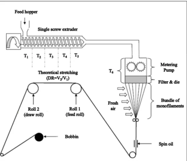
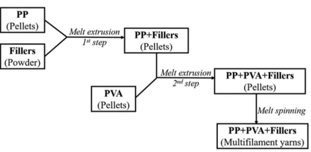
(6) Thèse de Xiang Yan, Université de Lille, 2019. 2.2.2. Melt spinning of polymer blends ........................................................ 71. 2.2.3. Preparation of the knitted fabrics ...................................................... 76. 2.2.4. Selective phase extraction experiment ............................................... 76. 2.3. Characterization methods .......................................................................... 76. 2.3.1. Thermal analyses ................................................................................. 76. 2.3.2. Morphology analyses ........................................................................... 78. 2.3.2.1. PVA accessibility measurement .......................................................... 78. 2.3.2.2. Scanning electron microscopy (SEM) observation ........................... 78. 2.3.2.3. Transmission electron scanning microscopy (TEM) observation ... 82. 2.3.2.4. Digital camera observation ................................................................. 83. 2.3.3. Rheometer tests .................................................................................... 83. 2.3.4. Melt flow index (MFI) ......................................................................... 83. 2.3.5. XRD analysis ........................................................................................ 84. 2.3.6. Mechanical properties ......................................................................... 84. 2.3.6.1. Tensile tests ........................................................................................... 84. 2.3.6.2. Dynamic mechanical analyses............................................................. 85. 2.3.7. Air permeability ................................................................................... 85. 2.3.8. Surface tension measurement ............................................................. 86. Chapter 3 Microstructure Evolution of Immiscible PP-PVA Blends Tuned by Polymer Ratio and Its Transformation into Fibers ................................................ 88 3.1. Polymeric compounds ................................................................................. 88. 3.1.1. Thermal properties of the blends ....................................................... 88. 3.1.2. Morphology of the polymer blends .................................................... 91. 3.1.3. Rheometer tests .................................................................................... 95. 3.1.4. Melt flow index (MFI) ......................................................................... 97. 3.2. Polymeric fibers ........................................................................................... 98. 3.2.1. Spinnability and morphology ............................................................. 98. 3.2.2. Mechanical properties ....................................................................... 102. 3.2.3. Textile creation by knitting technology............................................ 107. 3.3. Conclusion .................................................................................................. 109. Chapter 4 Microstructure Evolution of Immiscible PP-PVA Blends Incorporated with Silica Nanoparticles and Its Transformation into Fibers ............................ 112 4.1. Polymeric compounds ............................................................................... 112. 4.1.1. Prediction and confirmation of silica localization........................... 112 5. © 2019 Tous droits réservés.. lilliad.univ-lille.fr.
(7) Thèse de Xiang Yan, Université de Lille, 2019. 4.1.2. Morphology of the polymer blends .................................................. 117. 4.1.3. Rheometer tests .................................................................................. 120. 4.1.4. Melt flow index (MFI) ....................................................................... 122. 4.2. Polymeric fibers ......................................................................................... 123. 4.2.1. Localization of silica nanoparticles within the fibers ..................... 123. 4.2.2. Morphology of the fibers ................................................................... 126. 4.2.2.1. PVA cross-sectional dimensions ....................................................... 126. 4.2.2.2. PVA accessibility degree.................................................................... 129. 4.2.2.3. Crystalline structure .......................................................................... 131. 4.2.3. Mechanical properties of the fibers .................................................. 133. 4.2.3.1. Tensile tests ......................................................................................... 133. 4.2.3.2. DMA results........................................................................................ 137. 4.3. Conclusion .................................................................................................. 140. Chapter 5 Polypropylene/Poly(vinyl alcohol) Blends Compatibilized with Kaolinite Janus Hybrid Particles and Their Transformation into Fibers.......... 143 5.1. Polymeric compounds ............................................................................... 143. 5.1.1. Heat resistance properties of kaolinites and blends........................ 143. 5.1.2. Morphology of the nanocomposites.................................................. 144. 5.1.3. Rheometer tests .................................................................................. 149. 5.1.4. Melt flow index (MFI) ....................................................................... 151. 5.2. Polymeric fibers ......................................................................................... 152. 5.2.1. PVA accessibility of the fibers .......................................................... 152. 5.2.2. Mechanical properties of the fibers .................................................. 153. 5.2.3. Thermal properties of the porous fibers .......................................... 156. 5.3. Conclusion .................................................................................................. 158. Chapter 6 Melt Spinning of Polypropylene (Dispersed)/Poly(vinyl alcohol) (Matrix) Blends Compatibilized with Kaolinite Janus Hybrid Particles and Fabrication of PP Microfibers ................................................................................ 161 6.1. Polymeric compounds ............................................................................... 161. 6.1.1. Rheometer tests .................................................................................. 161. 6.1.2. Melt flow index (MFI) ....................................................................... 162. 6.2. Polymeric fibers ......................................................................................... 163. 6.2.1. Thermal stability of the microfibers ................................................ 163. 6.2.2. Morphology of the biphasic fibers .................................................... 165 6. © 2019 Tous droits réservés.. lilliad.univ-lille.fr.
(8) Thèse de Xiang Yan, Université de Lille, 2019. 6.2.3. Mechanical tests of the fibers ............................................................ 168. 6.2.4. Mechanical tests of the knitted fabrics............................................. 170. 6.2.5. Thermal properties of the PP microfibers ....................................... 172. 6.3. Conclusion .................................................................................................. 174. General Conclusions and Prospects ....................................................................... 175 References ................................................................................................................. 181 Appendix: Publications and Conferences .............................................................. 214. 7. © 2019 Tous droits réservés.. lilliad.univ-lille.fr.
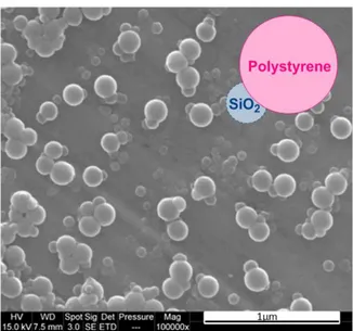
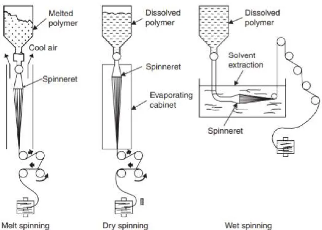
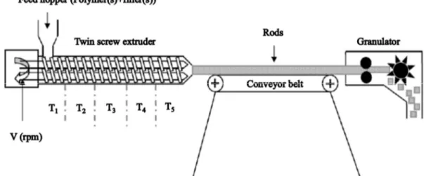
(9) Thèse de Xiang Yan, Université de Lille, 2019. List of Figures Figure 1-1 Chemical structure of polypropylene (omnexus.specialchem.com., 2019). ...................................................................................................................................... 21 Figure 1-2 Molecular configurations of the polypropylene (a) atactic; (b) syndiotactic; (c) isotactic (Left-handed Helix) (Krassig, 1984). ................................. 21 Figure 1-3 Different kinds of morphology observed by SEM analyses (a) Dispersed structure; (b) matrix-fiber-structure; (c) lamellar structure; (d) co-continuous structure (Pötschke and Paul., 2003)........................................................................................... 25 Figure 1-4 Molecular structures of PVA with different degrees of hydrolysis (Patachia et al., 2009)................................................................................................... 33 Figure 1-5 Chemical structures of POE (Harris, 2013). ............................................. 35 Figure 1-6 Repeat unit of sulfonated PET (AQ55S) (Ghanbari et al., 2013). ............ 37 Figure 1-7 Repeat unit of sulfopolyester (AQ48) (Wang et al., 2016b). .................... 37 Figure 1-8 Scheme of the possible evolution of biphasic morphology influenced by the incorporation of nanoparticles (de Luna and Filippone, 2016). ............................. 39 Figure 1-9 SEM images of the top of a typical kaolinite platelet; the scheme of kaolinite platelets; the crystal structure of three lamellae with the special chemical functions at the TS and OS basal (Weiss et al., 2013)................................................. 42 Figure 1-10 Different shapes of Janus particles (a) spherical , (b, c) two types of cylindrical, (d, e) disc-shaped JPs, (f−k) various kinds of dumbbell-shaped JPs with (f) asymmetric or snowman character, (g, k) symmetric appearance, (h) attached nodes, and (i) eccentric encapsulation. (l) Janus vesicles or capsules (Walther et al., 2013). ........................................................................................................................... 46 Figure 1-11 SEM images of the snowman-like Janus particles of PS and SiO2 (Caro et al., 2017). ..................................................................................................................... 47 Figure 1-12 Scheme of (a) the pristine kaolinite; (b) the modification of the tetrahedral surface (TS) by PDPS; (c) the modification of the octahedral surface (OS); (d) the incorporation of the modified kaolinite towards the biphasic interface of PS and PMMA (Weiss et al., 2013). ................................................................................. 48 Figure 1-13 Scheme of a co-rotating intermeshing twin-screw extruder (Hyun et al., 2011). ........................................................................................................................... 50 Figure 1-14 Scheme of melt spinning, dry spinning and wet spinning (Imura et al., 2014). ........................................................................................................................... 51 Figure 1-15 Devices of melt electrospinning and solution electrospinning (Lian and Meng, 2017). ................................................................................................................ 54 Figure 1-16 Scheme of the biphasic morphologies for specific usages (Macosko, 2000). ........................................................................................................................... 55 Figure 1-17 Mechanisms of fibrillation process in the elongational flow along with the spinnline in a certain condition (the diameter (D0)=0.6 mm with aspect ratio (L/D0) =2 of the capillary hole, volumetric flow rate (V)=0.78 cm3/min, take-up speed (v)=50 m/min, T=195°C) (Tran et al., 2014a). ............................................................ 57 8. © 2019 Tous droits réservés.. lilliad.univ-lille.fr.
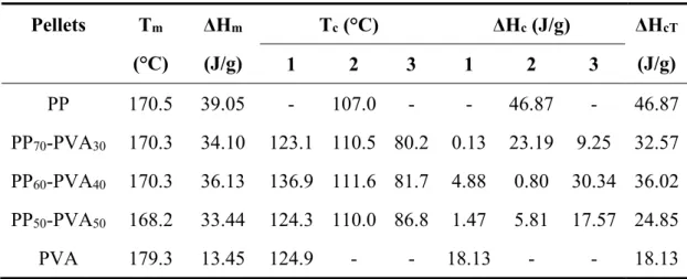
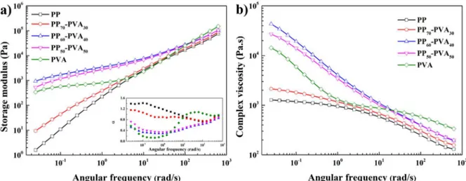
(10) Thèse de Xiang Yan, Université de Lille, 2019. Figure 1-18 Image of (a) the multifilament yarns from polypropylene/poly(ethylene terephthalate) (PP/PET) with the diameters of 30 micrometers; (b) the knitted fabrics from the PP/PET yarns; (c) SEM of the knitted yarns after the selective phase extraction (d) the zoomed image of (c) (Fakirov et al., 2014). .................................... 62 Figure 1-19 SEM images of PP-PVA fibers (50 wt.%/50 wt.%)(a) Before extraction; (b) After selective phase extraction (Robeson et al., 1994). ........................................ 63 Figure 2-1 The chemical structures of (a) hexadecylsilane; (b) dimethyldichlorosilane (pubchem.ncbi.nlm.nih.gov., 2019; upload.wikimedia.org., 2019). ............................ 68 Figure 2-2 Scheme of the synthesis of Janus kaolinite particles................................. 69 Figure 2-3 Scheme of the extrusion process of the PP-PVA blends without/with fillers. ........................................................................................................................... 70 Figure 2-4 Scheme of the melt spinning process of the PP-PVA blends without/with fillers. ........................................................................................................................... 72 Figure 2-5 The melt extrusion and melt spinning protocol of the polymers and fillers. ...................................................................................................................................... 74 Figure 2-6 Diagram of diameter measurement of PVA nodules of different shapes in PP-PVA blends. ........................................................................................................... 80 Figure 3-1 TGA results of neat and blend polymers of PP and PVA in N2 atmosphere (a) TGA curves; (b) DTG curves. ................................................................................ 89 Figure 3-2 DSC analyses of neat and blend polymers of PP and PVA (a) melting process in the 2nd cycle; (b) crystallization process in the 2nd cycle. ........................... 91 Figure 3-3 PVA accessibility degree of the PP-PVA blends with different mass ratios of polymers. ................................................................................................................. 93 Figure 3-4 SEM images of the pellets after melt extrusion with different mass ratios in longitudinal direction (a) PP70-PVA30; (b) PP60-PVA40; (c) PP50-PVA50 (PP: dark part; PVA: light part). .................................................................................................. 94 Figure 3-5 Rheological behaviours of neat PP, PP70-PVA30, PP60-PVA40, PP50-PVA50 and neat PVA at 190 °C. (a) Storage modulus and the slope of the storage modulus α(ω); (b) Complex viscosity. ....................................................................................... 96 Figure 3-6 Melt flow index (190°C, 2.16 kg) of neat and blend polymers of PP/PVA. ...................................................................................................................................... 97 Figure 3-7 PVA accessibility degree of polymer blends and digital photos of extracted fibers from (a) PP70-PVA30-DR2; (b) PP60-PVA40-DR2; (c) PP50-PVA50-DR2. ...................................................................................................................................... 99 Figure 3-8 SEM observation of PP-PVA blend fibers before and after extraction (a) PP50-PVA50-DR2; (b) PP50-PVA50-DR2-Ex; (c) PP60-PVA40-DR2; (d) PP60-PVA40DR2-Ex; (e) PP70-PVA30-DR2; (f) PP70-PVA30-DR2-Ex; (g) PP70-PVA30-DR3; (h) PP70-PVA30-DR3-Ex; (i) the cross-sections of PP70-PVA30-DR2 fibers; (j) the crosssections of PP70-PVA30-DR3 fibers. ........................................................................... 101 Figure 3-9 XRD spectra of (a) PP and PVA fibers with different draw ratios; (b) PPPVA blend fibers with different fractions and draw ratios. ....................................... 102 Figure 3-10 Stress-strain curves of (a) neat fibers from PP or PVA with a DR value of 2 or 3 with the zoomed figure; (b) PP-PVA fibers of different fractions with a DR 9. © 2019 Tous droits réservés.. lilliad.univ-lille.fr.
(11) Thèse de Xiang Yan, Université de Lille, 2019. value of 2; (c) PP70-PVA30 with different DR values before and after selective phase extraction.................................................................................................................... 105 Figure 3-11 (a) Storage moduli of PP-PVA fibers with different fractions; (b) Tan δ of PP-PVA fibers with different fractions. ................................................................ 106 Figure 3-12 Experimental values and simulated curves of storage moduli of PP-PVA fibers as a function of PVA weight fraction near room temperature. ........................ 107 Figure 3-13 Stress-strain curves of the knitted fabrics from PP70-PVA30-DR3 before and after selective phase extraction. .......................................................................... 109 Figure 4-1 TEM observation of the PP-PVA blends with silica nanoparticles. (a) PP70-PVA30-SiS5505; (b) PP70-PVA30-SiR816; (c) PP70-PVA30-SiR972; (d) PP70-PVA30SiR972 (higher magnification). .................................................................................... 116 Figure 4-2 PVA accessibility degree of the PP-PVA blends with 1 wt.% of silica nanoparticles with different hydrophobicity (the red dotted line represents the value of PP70-PVA30). .............................................................................................................. 117 Figure 4-3 SEM images of the longitudinal section of the extrudates. (a)(b) PP70PVA30; (c) PP70-PVA30-SiS5505; (d) PP70-PVA30-SiR816; (e)(f) PP70-PVA30-SiR972. ... 118 Figure 4-4 Rheological behaviours of PP70-PVA30, PP70-PVA30-SiS5505, PP70-PVA30SiR816 and PP70-PVA30-SiR972 at 190 °C. (a) Storage modulus and α(ω); (b) Complex viscosity. .................................................................................................................... 121 Figure 4-5 Melt flow index (190°C, 2.16 kg) of PP70-PVA30 without/with different silica nanoparticles (the range between the two red dotted lines represents the spinnable zone). ......................................................................................................... 122 Figure 4-6 (a) Schematic figure of SEM sample preparation; (b) SEM image of an obliquely cut fiber from PP70-PVA30-DR3-Ex; Internal and external inner surfaces of (c)(d) PP70-PVA30-DR3-Ex; (e)(f) PP70-PVA30-SiS5505-DR3-Ex; (g)(h) PP70-PVA30SiR816-DR3-Ex; (i)(j) PP70-PVA30-SiR972-DR3-Ex. ..................................................... 125 Figure 4-7 SEM images of the fiber cross-sections without/with different silica nanoparticles (a) PP70-PVA30-DR2; (b) PP70-PVA30-SiS5505-DR2; (c) PP70-PVA30SiR816-DR2; (d) PP70-PVA30-SiR972-DR2. (e) schematic diagram about the thin layer acquired from a biphasic fiber. .................................................................................. 127 Figure 4-8 PVA accessibility of PP70-PVA30 without/with different silica nanoparticles in the form of extrudates and multifilament fibers with different draw ratios........................................................................................................................... 130 Figure 4-9 XRD spectra of PP70-PVA30 fibers without/with silica nanoparticles with the two tested draw ratios. ......................................................................................... 132 Figure 4-10 Stress-strain curves of PP fibers without/with different silica nanoparticles (a) DR=2; (b) DR=3. ........................................................................... 134 Figure 4-11 Stress-strain curves of PP70-PVA30 fibers without/with different silica nanoparticles (a) DR=2, before extraction; (b) DR=2, after extraction; (c) DR=3, before extraction; (d) DR=3, after extraction. ........................................................... 137 Figure 4-12 (a)(c) Storage modulus of PP70-PVA30 fibers without/with different silica nanoparticles with DR=2, 3; (b)(d) Tan delta of PP70-PVA30 fibers without/with different silica nanoparticles with DR=2, 3. .............................................................. 139 10. © 2019 Tous droits réservés.. lilliad.univ-lille.fr.
(12) Thèse de Xiang Yan, Université de Lille, 2019. Figure 4-13 Fitting of storage modulus of PP70-PVA30 fiber containing different silica nanoparticles with different DR by Coran’s model (a) DR=2; (b) DR=3. ................ 139 Figure 5-1 TG and DTG curves of KL and KJ particles in nitrogen and air atmosphere. (a) TG curves in a nitrogen atmosphere; (b) DTG curves in a nitrogen atmosphere; (c) TG curves in an air atmosphere; (d) DTG curves in an air atmosphere. .................................................................................................................................... 144 Figure 5-2 SEM images of PP70-PVA*30 blends with pristine and modified kaolinites (samples were cryo-fractured after treatment in liquid nitrogen). (a) PP70-PVA*30KL5; (b) PP70-PVA*30- KL5 (BSE); (c) PP70-PVA*30-KJ5; (d) PP70-PVA*30- KJ5 (BSE) (BSE images: PP: dark part; PVA: light part; kaolinite particles: white dots). ......... 145 Figure 5-3 PVA accessibility degree of PP70-PVA30 extrudates with pristine and modified kaolinites at 1 or 5 wt.%. ............................................................................ 146 Figure 5-4 Particle diameter distribution and the SEM images of the PVA nodules inside PP matrix after the rheometer measurement (a) PP70-PVA*30 (b) PP70-PVA*30KL1 (c) PP70-PVA*30-KJ1 (d) PP70-PVA*30-KJ5......................................................... 149 Figure 5-5 Rheological results of PP70-PVA*30 blends and pure components at 190 °C (a)(b) storage moduli and complex viscosities of PP70-PVA*30 blends without/with kaolinite particles (c)(d) storage moduli and complex viscosities of PP, PVA, PP70PVA*30 blends without/with 5 wt.% of KJ Janus particles. ....................................... 151 Figure 5-6 Melt flow index (190°C, 2.16 kg) of PP70-PVA30 blends with different kaolinite particles. ...................................................................................................... 152 Figure 5-7 PVA accessibility of PP70-PVA30 fibers with pristine and modified kaolinites. ................................................................................................................... 153 Figure 5-8 Stress-strain curves of PP70-PVA*30 fibers with pristine and modified kaolinite particles (a) before extraction; (b) after extraction; (c) neat PP fibers. ...... 156 Figure 5-9 DSC spectra of (a) neat PP and PP70-PVA*30-Ex (b) PP70-PVA*30 without/with kaolinite particles after selective phase extraction. .............................. 157 Figure 6-1 Rheological results of PP30-PVA*70 blends with/without kaolinite particles at 190 °C (a) storage modulus; (b) complex viscosity. .............................................. 162 Figure 6-2 Melt flow index (190°C, 2.16 kg) of PP, PVA* and the blends with/without kaolinite particles.................................................................................. 163 Figure 6-3 TGA results of the PP microfibers extracted from PP-PVA* blend fibers. .................................................................................................................................... 164 Figure 6-4 SEM images of knitted PP30-PVA*70-DR4 fabrics before and after selective phase extraction at various magnifications. ................................................ 166 Figure 6-5 Further zoomed figures of knitted PP30-PVA*70-DR4 fabrics after selective phase extraction. ........................................................................................................ 167 Figure 6-6 SEM images of (a) PP30-PVA*70-KL2-DR4 fibers; (b) BSE of (a); (c) PP30PVA*70-KJ2-DR4 fibers; (d) BSE of (c). .................................................................... 168 Figure 6-7 Stress-strain curves of (a) PP30-PVA*70 fibers with/without kaolinites with DR=2; (b) PP30-PVA*70 fibers with/without kaolinites with DR=4. ......................... 170 Figure 6-8 Stress-strain curves of knitted fabrics from PP30-PVA*70 fibers (a) before selective phase extraction; (b) after selective phase extraction. ................................ 172 11. © 2019 Tous droits réservés.. lilliad.univ-lille.fr.
(13) Thèse de Xiang Yan, Université de Lille, 2019. Figure 6-9 DSC spectra of PP microfibers (a) extracted from PP30-PVA*70 with/without kaolinite particles with DR=2; (b) extracted from PP30-PVA*70 with/without kaolinite particles with DR=4............................................................... 173. 12. © 2019 Tous droits réservés.. lilliad.univ-lille.fr.
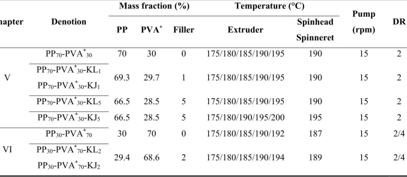
(14) Thèse de Xiang Yan, Université de Lille, 2019. List of Tables Table 1-1 Specific gravity of various fibers. ............................................................... 22 Table 1-2 Various particles and their representative dimensions and functionality. .. 40 Table 2-1 The component fractions and melt spinning conditions in Chapter III and IV. ................................................................................................................................ 74 Table 2-2 The component fractions and melt spinning conditions in Chapter V and VI. ................................................................................................................................ 75 Table 3-1 TG data of PP and PVA in N2 atmosphere. ................................................ 90 Table 3-2 Thermal parameters of neat and blend PP-PVA materials. ........................ 91 Table 3-3 XRD peak data of PP-containing fibers. ................................................... 102 Table 3-4 Mechanical properties of blend fibers of PP and PVA with different ratios. .................................................................................................................................... 104 Table 3-5 Mechanical properties and air permeability of the fabrics knitted from PP70-PVA30-DR3 fibers. ............................................................................................. 108 Table 4-1 Surface tension of polymers and fumed silicas. ....................................... 113 Table 4-2 Interfacial energy between different components (silica with polymer, polymer with polymer) using geometric and harmonic mean equations. .................. 114 Table 4-3 Wetting parameters ωPP-PVA calculated with geometric and harmonic data and the localization predictions of silica nanoparticles. ............................................ 115 Table 4-4 Confirmation of the localization of nanoparticles in PP-PVA blends from TEM images. .............................................................................................................. 116 Table 4-5 Characteristics of the microstructure of extrudates from PP-PVA blends. .................................................................................................................................... 119 Table 4-6 Diameter of the pores inside the representative fibers. ............................. 128 Table 4-7 XRD data of PP70-PVA30 fibers with silica nanoparticles with DR=2 and 3. .................................................................................................................................... 133 Table 4-8 Mechanical properties of PP fibers without/with silica nanoparticles. ..... 134 Table 4-9 Mechanical properties of PP70-PVA30 fibers with different silica nanoparticles with DR=2 and 3.................................................................................. 136 Table 5-1 Mechanical properties of PP70-PVA*30 fibers containing kaolinite particles and neat PP fibers....................................................................................................... 155 Table 5-2 Thermal properties of neat PP and PP70-PVA30 fibers after extraction. ... 158 Table 6-1 Residues (700°C) of PP microfibers extracted from PP-PVA* blend fibers. .................................................................................................................................... 165 Table 6-2 Mechanical properties of the composite fibers from PP30-PVA*70 with/without kaolinite particles.................................................................................. 169 Table 6-3 Mechanical properties of the knitted fabrics from PP30-PVA*70 fibers. ... 171 Table 6-4 Thermal properties of PP microfibers extracted from PP30-PVA*70 with/without kaolinite particles with different draw ratios. ....................................... 173. 13. © 2019 Tous droits réservés.. lilliad.univ-lille.fr.
(15) Thèse de Xiang Yan, Université de Lille, 2019. 14. © 2019 Tous droits réservés.. lilliad.univ-lille.fr.
(16) Thèse de Xiang Yan, Université de Lille, 2019. Introduction Polymer blending is a common method to endow the materials with synergetic properties. The blending strategy also offers the possibility of manufacturing porous materials, if one of the phases can be removed. The method is carried out in two consecutive steps, i.e., (i) target and sacrificial polymers are mixed at melting state without adding any solvent, and (ii) the sacrificial polymer is extracted with the solvent to obtain a porous material. With the development of nanotechnology, more and more nanoparticles are being utilized to tailor the microstructure. Apart from regulating the structure, nanoparticles can endow the material with additional properties. In the case that the nanoparticles are localized at the interface, after the etching of sacrificial phase, surface modified scaffold with nanoparticles can be obtained. It provides a possibility to prepare surface functionalized material. This strategy can be also extended to textile area with the aid of melt spinning technology. Polypropylene (PP) is a non-polar polymer with a good fiber-forming ability for textile use. Thermoplastic polyvinyl alcohol (PVA), as polar polymer, is immiscible with PP, and it can be removed in warm water as sacrificial phase. PVA is biodegradable and water-soluble, and also has important fiber-forming properties. Melt spinning is one of the main routes to produce upstream polymeric fibers for textile use. The related technology (e.g., twisting, knitting, weaving) can be applied with melt-spun fibers. This PhD work is funded by China Scholarship Council (CSC), and performed in Laboratoire de Génie et Matériaux Textiles (GEMTEX, ENSAIT, France). The objective is to fabricate the (nano)particle-tailored high-specific-area polypropylene textile products. In Chapter 1, a literature survey was conducted. The application of polypropylene and the meltable water-soluble polymers were introduced. Some important factors concerning the biphasic morphology prediction and control were investigated. Afterwards, the information about the (nano)particles as compatiblizers was also 15. © 2019 Tous droits réservés.. lilliad.univ-lille.fr.
(17) Thèse de Xiang Yan, Université de Lille, 2019. reported, including the homogenously modified and the Janus particles. The related survey of transformation of biphasic blends to multifilament yarns was presented, for fabricating porous fibers/microfibers. In Chapter 3, blends with three different mass ratios of PP/PVA (70/30, 60/40, 50/50 (wt.%/wt.%)) were compounded and manufactured into fibers. The purpose of this research is to study the morphological evolution from extrudates to multifilament yarns of PP-PVA, through different tests along the whole textile production process. Different PP/PVA ratios have been studied to optimize the appropriate formulation to obtain porous PP-PVA blend fibers by melt spinning followed by phase extraction. In Chapter 4, efforts were made to use silica nanoparticles with different surface chemistries into the biphasic fibers, of which their mass ratio was 70/30 (PP to PVA). Efforts were made to develop blends with interface distributed silicas, and the feasibility of fabricating surface-modified porous PP fibers was also demonstrated. In Chapter 5, the Janus kaolinite particles were firstly used in PP-PVA biphasic systems with the mass ratio of 70/30. The Janus particles have a stronger affinity towards the biphasic interface compared with the conventional homogenously modified particles. Therefore, the materials were manufactured into multifilament yarns by melt spinning technology to fabricate the surface-tailored PP porous fibers. In Chapter 6, the mass ratio of PP to PVA was reversed to 30/70 in order to fabricate the PP matrix/PVA disperse fiber. Therefore, the PP microfibers were expected to obtained after the removal of PVA. In addition, the incorporation of Janus kaolinite particles was also attempted. In the research, emphasis was put on both of the extrudates and the fibers of the polymer blends, as well as the knitted fabrics. The melt flow index (MFI) was determined to ensure the spinnability of the polymer mixture within an appropriate temperature range. To evaluate the morphology change including the biphasic structure and filler localization, the scanning microscopy analyses (SEM) and transmission electron scanning microscopy (TEM) were carried out. The measurement of PVA accessibility degree and the rheological analyses were also combined. The mechanical 16. © 2019 Tous droits réservés.. lilliad.univ-lille.fr.
(18) Thèse de Xiang Yan, Université de Lille, 2019. measurement of the obtained fibers and fabrics was also a key investigation. In addition, the thermal properties and aggregation structures of the blends were examined.. 17. © 2019 Tous droits réservés.. lilliad.univ-lille.fr.
(19) Thèse de Xiang Yan, Université de Lille, 2019. 18. © 2019 Tous droits réservés.. lilliad.univ-lille.fr.
(20) Thèse de Xiang Yan, Université de Lille, 2019. Chapter I: State of the Art. 19. © 2019 Tous droits réservés.. lilliad.univ-lille.fr.
(21) Thèse de Xiang Yan, Université de Lille, 2019. Chapter 1 State of the Art In this chapter, a literature survey is started with the introduction of polypropylene, one of the most conventional thermoplastic polymers in people’s life. It demonstrates that the functionality of PP is difficult to be achieved, sometimes PP material should be paired with some other polymers to be given more possibilities for derived use. Afterward, the basic concept, processing methods as well as prediction methods are illustrated. Water-soluble polymers are an essential branch, can also accompany with other polymers to form polymer pairs. For the lack of compatibility, the surfactant is often required to make up with the drawbacks. Furthermore, the melt spinning technology in order to fabricate the biphasic fibers is introduced. If one of the phases is removed, the porous fibers or microfibers may be obtained.. 1.1 Application of polypropylene Polypropylene (PP) was discovered in 1954 by the Nobel prize winner, an Italian scientist Giulio Natta and became popular very quickly. It is a classical non-polar polymer from inexpensive petroleum derivative with excellent resistant properties against chemical reagent as well as mechanical abuse. Furthermore, the thermal stability of PP provides the feasibility in many fields, compared with polyethylene. PP belongs to a vinyl polymer, of which the structure is shown in Figure 1-1 (omnexus.specialchem.com., 2019). There are mainly three kinds of molecular configuration, including atactic, syndiotactic and isotactic polypropylene, which is displayed in Figure 1-2 (Krassig, 1984). In addition, the hemiisotactic polypropylene is also an interesting kind in macromolecular stereochemistry, as a coexistence of order and disorder with the even monomeric units of the same configuration and odd units of a random configuration (Karger-Kocsis and Bárány, 2019). One of the important uses is to be manufactured into fibers. The PP polymer candidate is normally isotactic, of which the commercial products were available in 20. © 2019 Tous droits réservés.. lilliad.univ-lille.fr.
(22) Thèse de Xiang Yan, Université de Lille, 2019. 1957, and its fibrous products appeared immediately since the late 1950s (Cook, 1968). In addition, syndiotactic polypropylene can be also manufactured into fibers revealed by a patent (Gownder and Nguyen, 2006), and they were found have a higher tenacity compared with the isotactic polypropylene. Meanwhile, the PP material lacks reactive groups for being functionalized. However, the melt processing temperature span of PP is relatively wide, which provides feasibility to be paired with another polymer with functionality in the melt manufacturing process. In addition, the PP fibers are composed of aliphatic hydrocarbon polymers, therefore, the surface energies are relatively lower than those of other thermoplastic fibers from the polar polymer (Ugbolue, 2017).. Figure 1-1 Chemical structure of polypropylene (omnexus.specialchem.com., 2019).. Figure 1-2 Molecular configurations of the polypropylene (a) atactic; (b) syndiotactic; (c) isotactic (Left-handed Helix) (Krassig, 1984).. 21. © 2019 Tous droits réservés.. lilliad.univ-lille.fr.
(23) Thèse de Xiang Yan, Université de Lille, 2019. PP is one of the cheapest synthetic polymers, and it has an outstanding fiberforming ability for potential textile domains. Its low density offers the possibility of being float as robs, nets or other forms of technical textiles (Pritchard et al., 2000). The specific gravity of some kinds of fibers in the textile industry are listed in Table 1-1 (Galanti and Mantell, 1965). It is found that polypropylene fibers have an outstanding advantage of specific gravity as 0.90-0.92 compared with other industrialized fibers. In addition, the PP fibers have an exceptionally low thermal conductivity, which can be used in for insulating applications. PP can also be a very good electronic insulator with low power loss even in the condition of radio frequencies. The crystallinity of PP is from 40% to 60% (Maddah, 2016). The mechanical properties of the PP fibers are dominantly influenced by the crystallinity degree, crystalline morphology, molar mass and chains orientation.. Table 1-1 Specific gravity of various fibers. Fiber. Specific Gravity. Polypropylene. 0.90-0.92. Cotton. 1.50-1.55. Wool. 1.30-1.32. Cellulose. 1.52. Cellulose acetate. 1.32. Polyamides. 1.14. Polyacrylonitrile. 1.14-1.17. Polyethylene terephthalate (PET). 1.38-1.39. Copolymer of acrylonitrile and vinyl chloride. 1.30. Polyvinylidene chloride (PVDC). 1.72. Glass fiber. 2.54. 22. © 2019 Tous droits réservés.. lilliad.univ-lille.fr.
(24) Thèse de Xiang Yan, Université de Lille, 2019. 1.2 Immiscible polymer blends When two polymers are mixed, the polymer blends can be miscible, partially miscible or immiscible (molecular level). Immiscible polymer blending is an ideal strategy for endowing the materials with additional as well as combined properties. The phase behaviors of polymer blends (macromolecules) are different from those of the small molecules, for the entropy of mixing the small molecules provides the driving force for miscibility, but the that of mixing the macromolecules can be negligible. Quantitative calculation starts with the free energy ∆Gm, which determines the miscibility of the polymer blends as shown in Equation 1-1.. Gm Hm T Sm Equation 1-1. where ∆Gm, ∆Hm and ∆Sm represent the Gibbs energy, enthalpy as well as entropy of mixing, respectively. Two conditions concerning ∆Gm are required to be fulfilled with regard to miscibility:. Gm 0. 2 (Gm ) 0 2 i T , p where ∆Gm represents the molar Gibbs free energy of mixing, ϕ is the volume fraction of the component i. Polymers have low entropic gain, and ∆Sm is small and positive. In most of the conditions, the mixing is commitment with endothermic process, which indicates that ∆Hm is positive. It results in the positive values of ∆Gm, representing the immiscibility. Therefore, in most of the cases, the blends exhibit immiscible. 23. © 2019 Tous droits réservés.. lilliad.univ-lille.fr.
(25) Thèse de Xiang Yan, Université de Lille, 2019. On occasion, the immiscible polymers and miscible polymers can be converted to each other, due to the change of the environment, including temperature, pressure or the polymer fractions (Thomas et al., 2014). Most of the polymer pairs are thermodynamically immiscible due to the low mixing entropy (Chen et al., 2005; Schmidt et al., 2002). The morphology control of the immiscible blends is of great significance. There are several possibilities of the biphasic morphology of the blends, including dispersed structure, matrix-fiber-structure, lamellar structure and co-continuous structure, displayed in Figure 1-3 (Pötschke and Paul., 2003), sometimes the structure can be complicated and multifarious due to different raw materials and manufacturing conditions.. 24. © 2019 Tous droits réservés.. lilliad.univ-lille.fr.
(26) Thèse de Xiang Yan, Université de Lille, 2019. Figure 1-3 Different kinds of morphology observed by SEM analyses (a) Dispersed structure; (b) matrix-fiber-structure; (c) lamellar structure; (d) co-continuous structure (Pötschke and Paul., 2003).. 1.3 Prediction of biphasic morphology Many factors determine the morphology of the blends, and many researchers have proposed several practical models to make related predictions.. 1.3.1 Viscosity and elasticity ratios The biphasic morphology is correlated with their viscoelasticity, which has been introduced in detail by Mekhilef and Verhoogt (1996). Avgeropoulos et al. (1976) gave 25. © 2019 Tous droits réservés.. lilliad.univ-lille.fr.
(27) Thèse de Xiang Yan, Université de Lille, 2019. a semi-empirical formula concerning the relationship between torque ratio and the polymer volume fraction of phase inversion. Non-uniform stress fields exist in the same processing device; therefore, the result only serves as an approximation (Pötschke and Paul., 2003). The related equation is illustrated in Equation 1-2.. T1 1 T2 2. Equation 1-2. where the Ti represents the torque of polymer i, and ϕi represents the volume fraction of polymer i. Torque symbolizes the shearing and elongational forces during the manufacturing inside the compounding device. This formula was evolved towards the relationship between viscosity and volume fraction of phase inversion, completed by Miles and Zurek (1988), shown in Equation 1-3.. 1 () 1 Equation 1-3 2 () 2 where the 𝜂 (𝛾̇ ) represents the viscosity of phase i at a certain low shear rate. In addition, the viscosity ratio can also determine the feasibility of the fibrillation of the minor phase, if phase 1 is regarded as the minor phase. Tsebrenko et al. (1980) and White and Min (1985) found that if μ was close to or lower than 1, the fibrillar distribution of minor phase appeared in the blends. If μ is low, the drops are easy to be elongated due to the shear flow, and with the increment of μ values, the droplet is easier to break up into short fibrils. If μ is higher than 1 the deformation in the extrudate was more insignificant. Furthermore, with tremendously high viscosity ratios, the droplets do not deform in the shear flow, but still possibly occurred in the extensional flow (Bentley and Leal, 1986).. 26. © 2019 Tous droits réservés.. lilliad.univ-lille.fr.
(28) Thèse de Xiang Yan, Université de Lille, 2019. Metelkhin and Blekht (1984) proposed a formula concerning the phase inversion and viscosity ratio, evolved from Tomotika’s theory (thread instability) (Tomotika, 1935). A thread-like dispersed phase around another liquid has the tendency of breaking up due to the interfacial tension. The related equation is shown in Equation 1-4 to predict the critical volume fraction for biphasic phase inversion.. 2 =[1+F( ) ]1 Equation 1-4 2 Where F()=1+2.25log()+1.81[log()] , in which λ represents the viscosity ratio.. Based on the previous discussion, Utracki established an updated formula as Equation 1-5.. [ ]m. 2 m 2i = 1 m 1i . Equation 1-5. where [η] represents the intrinsic viscosity, ϕm represents the maximum packing volume fraction, and ϕ1i and ϕ2i represent the volume fraction of the continuous and dispersed phases at the phase inversion point. The elasticity ratio is also a determining factor, especially when the viscosity ratio of the dispersed phase to the matrix phase is too high. Bourry and Favis (1998) proposed a formula connecting the volume fraction to the storage module (G') and the loss tangent (tan δ), respectively illustrated in Equation 1-6 and Equation 1-7.. 1 G '1 = Equation 1-6 2 G '2 1 tan1 = Equation 1-7 2 tan2 27. © 2019 Tous droits réservés.. lilliad.univ-lille.fr.
(29) Thèse de Xiang Yan, Université de Lille, 2019. Where G'i represents the storage modulus of polymer i, and tan δi represents the loss tangent of polymer i. The prediction is not accurate but can give a main trend influenced by the elasticity ratios.. 1.3.2 Surface tension The surface tension of the components is also of significant importance for the final morphology of the blends. Low interfacial stresses promote droplet rupture rather than the formation of the elongated fibrous phase (White and Min, 1985). Willemse et al. (1999) demonstrated that the interfacial tension determines the region of the cocontinuity. They proposed a formula concerning the geometrical requirements for the co-continuity as in Equation 1-8.. 1. d ,cc. 1.38 0.0213 m R0 . 4.2. Equation 1-8. The lower limit of the minor phase volume fraction can be calculated, of which the co-continuous morphologies can be reached, for the specific polymeric system and blending conditions. The limit for co-continuity (ϕd,cc) can be estimated in terms of interfacial tension γ, the viscosity of matrix phase ηm, the shear rate 𝛾̇ , the equivalent sphere radius of the minor phase R0. Compared with miscible systems, the linear viscoelasticity is strongly influenced by the microstructures of the biphasic phases. Palierne (1990) made the connection of the morphology with the viscoelastic response in an emulsion system, well known as Palierne’s Model. Graebling et al. (1993) simplified the model and regarded the particle size distribution is narrow with the Rv/Rn value not exceeding 2, where Rv is the volume average radius and Rn is the number average radius. Thus, the complex modulus is in relationship with the interfacial tension γ and the droplet sizes Di, which is given in Equation 1-9.. 28. © 2019 Tous droits réservés.. lilliad.univ-lille.fr.
(30) Thèse de Xiang Yan, Université de Lille, 2019. 1 3i i Hm* (w) G w =G w +iG w =G w Equation 1-9 * 1 2 H ( w ) i i m *. '. ''. * m. Where 4 2Gm* w 5Gd* w Gd* w Gm* w 16Gm* w 19Gd* w D H*i w = i 40 * Gm w Gd* w 2Gd* w 3Gm* w 16Gm* w 19Gd* w Di. Many researchers simulated this formula from the rheological tests to calculate the surface tension, and different blending systems exhibit varied surface tension. For example, the surface tension of poly(trimethylene terephthalate) PTT/polyamide-12 (PA12) blends can reach as high as 7 mN/m (Asadinezhad et al., 2005), while that of poly (butylene succinate) (PBS)/polylactide (PLA) is significantly lower as 1.12 mN/m (Wu et al., 2012). In addition, there are also Yu’s, Bousmina’s models as well as Gramespacher and Meissner Model (G-M Model) to calculate the dynamic moduli (Yu et al., 2002; Bousmina, 1999; Gramespacher and Meissner, 1992). One of the most typical ones is G-M Model, evolved from the emulsion system developed by Choi and Schowalter (1975) as well as a linear mixing rule. The idea is that the complex shear modulus originates from the shear moduli of the biphasic phases and also the interface. Therefore, the complex, storage as well as loss moduli are obtained in Equation 1-10, Equation 1-11 and Equation 1-12, respectively.. G* () Gd* () (1)Gm* () Gint* (). G ( ) G d ( ) (1 )G m ( ) . Equation 1-10. 2 2 12 1 1 1 1 2 12 . Equation 1-11. 29. © 2019 Tous droits réservés.. lilliad.univ-lille.fr.
(31) Thèse de Xiang Yan, Université de Lille, 2019. G ( ) Gd ( ) (1 )Gm ( ) . 2 1 1 1 1 1 2 12 . Equation 1-12. Where . m 1 . 5K 2 5(5 K 2) 2 2 2( K 1) 8( K 1) 2 . 1 . (19 K 16)(2 K 3) R m 5(19 K 16) 1 40( K 1) 4( K 1)(2 K 3) . 2 . (19 K 16)(2 K 3) R m 3(19 K 16) 1 40( K 1) 4( K 1)(2 K 3) . with G’, G’m, and G’d being the blend, matrix, and dispersed phase storage moduli, respectively, G”, G”m, and G”d the blend, matrix, and dispersed phase loss moduli, respectively, G*, G*d, G*m, and G*int respectively the complex modulus of the blend, the complex modulus of the dispersed phase, the complex modulus of the matrix, and the complex modulus of the interface. φ is the volume fraction of the dispersed phase, ω is the frequency of oscillation, η, ηm and ηd are the blend, matrix, and dispersed phase zero-shear viscosities, respectively. K=η/ηm represents the viscosity ratio, ϒ represents the interfacial tension between the phases of the blend, and R represents the average radius of the monodispersed droplets.. 1.3.3 Storage moduli The storage moduli represent the stiffness of the sample, based on which some modeling can be carried out to dig the morphology evolution of the biphasic polymers. The parallel and series modes are indicated in Equation 1-13 and Equation 1-14, respectively (Moly et al., 2006).. 30. © 2019 Tous droits réservés.. lilliad.univ-lille.fr.
(32) Thèse de Xiang Yan, Université de Lille, 2019. Mu M11 M 22 Equation 1-13. 1 1 2 Equation 1-14 ML M1 M2 where Mi represents the mechanical property of each polymer (mainly reflected in storage modulus); Φi represents the volume fractions. Mu represents the upper bound of the blends, while ML represents the lower bound of the blends. For the parallel model, the components are arranged parallelly. Therefore, the applied stress elongates both of the components as the same extent. For the series model, the components are arranged in series. In this case, the applied stress elongates the components not conventionally as the same extent. The parallel model represents the co-continuous structure, in which both of the two components have a great contribution. In addition, Coran and Takayanagi proposed the related models evolved from the basic ones. Coran’s model is shown in Equation 1-15 (Coran, 1988).. M f M u M L M L Equation 1-15. Where similarly, Mu represents the upper bound of the blends, while ML represents the lower bound of the blends. f varies between zero and unity for the binary blends, which means the Coran’s model is between the upper and lower bounds. Furthermore, in Takayanagi model is shown in Equation 1-16 (Dickie, 1973). 1. 1- E (1 )E1 E1 E2 . Equation 1-16. where λ represents the degree of series-parallel coupling (combination mode), E1 and E2 represent the moduli of the matrix and dispersed phase of the blends.. 31. © 2019 Tous droits réservés.. lilliad.univ-lille.fr.
(33) Thèse de Xiang Yan, Université de Lille, 2019. The micromechanical models exhibit a good tool to demonstrate combination mode of the blends, sometimes also representing the degree of co-continuity. However, the drawback is the model lacks the information concerning the interfacial properties, compared with the Palierne or G-M Models. In addition, the micromechanical models are more suitable for the dynamic moduli (Asadinezhad et al., 2005).. 1.4 Immiscible blends with water-soluble polymers Polymer blends containing one soluble sacrificial phase gives the materials possibilities to fabricate more types of products. After the removal of the sacrificial phase, the porous materials or numerous fragmented materials can be obtained and served as potential functional materials, for they own significantly high specific areas. Among the soluble polymers, the water-soluble polymers are playing a more and more important role as sacrificial polymers, for the toxic organic solvents can be avoided. Water-soluble polymers mainly contain hydrophilic functional groups, such as alcohol, pyrrolidone, amide and ether (Halake et al., 2014). There are several available soluble polymers, such as poly (vinyl alcohol) (PVA/PVOH), polyoxyethylene (POE), sulfopolyester (SP).. 1.4.1 Poly(vinyl alcohol) (PVA/PVOH) PVA, as a synthetic and semicrystalline polymer with hydroxyl groups, with a backbone containing only carbon atoms. It possesses an excellent oxygen barrier and dyeing properties, and mechanical strength as well as biodegradable properties in both anaerobic and aerobic environment (Kim et al., 2015; Strecka et al., 2010; Halima, 2016). PVA can be dissolved in water, and its hydrolysis degree influences its water dissolution (Robeson et al., 1994). Hermann and Haehnel in Germany firstly prepared it, in 1924, and it became industrialized using the hydrolysis of polyvinyl acetate (PVAc) (Goodship and Jacobs, 2009). The degree of hydrolysis makes the PVA products varied, mainly divided into two kinds, fully hydrolyzed and partially hydrolyzed ones. The related molecular structures of PVA are displayed in Figure 1-4, and normally the PVA 32. © 2019 Tous droits réservés.. lilliad.univ-lille.fr.
(34) Thèse de Xiang Yan, Université de Lille, 2019. are copolymers containing vinyl alcohol and vinyl acetate (Patachia et al., 2009). It is used in many fields, such as textile, emulsifier, coating, and adhesives (Jang and Lee, 2003).. Figure 1-4 Molecular structures of PVA with different degrees of hydrolysis (Patachia et al., 2009).. In most of the cases, PVA is manufactured by wet process dissolved by water. Nowadays, melt processing technology is also employed for PVA manufacturing, in which glycerin, as a plasticizer, is usually added to decrease its melting point. The gas barrier properties of PVA is provided by its small, dense and closely packed “monoclinic” crystallite. Thus, some researchers adopted PVA into the packaging materials to enhance their gas barrier properties and broaden the extensive applications. Jang et al. (2004) used PVA to enhance the oxygen barrier property of biaxially oriented PP film over 130 times. The oxygen barrier was enhanced with the increase of the PP viscosity and the draw ratio. Kim et al. (2015) also introduced PVA into low-density polyethylene (LDPE) for packaging used to enhance the oxygen barrier. Meanwhile, due to the easy interaction of water vapor with polar hydroxyl groups, the water absorbency of LDPE was greatly enhanced. Therefore, it is more suitable for the packaging the low-moisture goods. Aimed at its biodegradable ability, Brandalise et al. blended high recycled density polyethylene (HDPEr) and PVA compatibilized with 33. © 2019 Tous droits réservés.. lilliad.univ-lille.fr.
(35) Thèse de Xiang Yan, Université de Lille, 2019. maleic anhydride-grafted HDPEr (HDPEr-AM) to discover its potential agricultural film use (Brandalise et al., 2009). The HDPEr crystallization was found to be increased from 56% to over 88% due to the presence of PVA. However, the overall crystallinity was decreased due to the low crystallinity of PVA. PVA is an important raw material for chemical fibers with good fiber-forming properties, which was commercialized since 1950s (Kim et al., 2016). Segawa et al. (1974) investigated the blends of PVA with polyolefins in which the pellets were sheared in an aqueous solution with inorganic salt to prevent the dissolution of PVA, and afterwards formed into papers. Robeson et al. (1994) initially removed the PVA phase by water to obtain microfibers. For the fabrication of polyvinyl alcohol/polypropylene biphasic fibers, Ku and Lin (2005, 2014) had in-depth investigations. The influence of temperature, shear rate and blending ratios on the rheological behaviors of the PVA/PP blends in capillary extrusions was investigated. PP and PVA have similar shear-sensitivity, between which PVA has a higher sensitivity. It is found that the viscosities of the blends are lower than those of the two components. In addition, it is revealed that the non-Newtonian indices as well as the activation energies of the blends are increased compared with those of the neat polymers. When 60 wt.% of PVA is incorporated, the viscosity of blends is more sensitive to temperature rather than the shear rate. With the increment of the shear rate, the impact of the temperature and polymer fractions on flow behavior is weakened. Furthermore, the melt spinning method was utilized to demonstrate the uniaxial elongational flow properties of the PP/PVA blends. It is revealed that the draw and blending ratios are key factors influencing the elongational flow behaviors, while temperature variation has little impact on the related behaviors. The convergence of blending ratio (when the proportion of polymer components in the total amount is close to each other) causes higher elongation rates and lower elongational resistance, which is not beneficial for melt spinning manufacturing.. 34. © 2019 Tous droits réservés.. lilliad.univ-lille.fr.
(36) Thèse de Xiang Yan, Université de Lille, 2019. 1.4.2 Polyoxyethylene (POE) POE is also denoted as polyethylene glycol (PEG), poly(ethylene oxide) PEO, and their nomenclature is usually decided by their molecular weight (MW). The corresponding chemical structures are displayed in Figure 1-5 (Harris, 2013). PEG represents the oligomers and polymers with a MW below 20,000 g/mol, and the polymers with higher values can be labeled as PEOs, both of which can be used as POE. The melting point of POE with a high MW is approximately 65°C. The monomer is ethylene oxide from the oxidation of ethylene by oxygen, and they are polymerized by oxyalkylation to form the polymers (Sheth et al., 1997). It is also a water-soluble polymer with biocompatible, pharmacologically inactive characteristics. It is still an interesting topic to introduce POE into the polyolefin, and Tang and Huang (1994) fabricated PP/PEO blends with a compatibilizer (PP-MA)-g-POE, and POE undergoes fractionated crystallization. The PEO was added into PLLA to modify the mechanical strength, hydrophilicity, degradation rate as well as the crystallization kinetics (do Carmo Rufino and Felisberti, 2016). It is revealed that the PLLA crystal is changed from α’-form to α-form with the increment of POE, and the entrapped POE undergoes the confined fractional crystallization as well. Many bio-sourced materials lack satisfactory mechanical performances. Yu et al. (2013) introduced POE into the matrix of plasticized-starch to enhance its mechanical properties, and Young’s modulus is elevated. In addition, POE is a common antistatic and dye fixing agent of polyolefinic fabrics (Tang and Huang, 1994). For the melting point of POE is very low, therefore, a large amount of POE is not suitable to be paired with polymer with a high melting point. The reason is that at a high temperature of manufacturing, the viscosity of POE becomes too low and it is difficult to achieve a stable fabrication.. Figure 1-5 Chemical structures of POE (Harris, 2013).. 35. © 2019 Tous droits réservés.. lilliad.univ-lille.fr.
(37) Thèse de Xiang Yan, Université de Lille, 2019. 1.4.3. Sulfopolyester (SP). Polyester is one of the most common thermoplastic resin, and poly(ethylene terephthalate) (PET) is the most important branch, which has been extensively fabricated into clothing fibers and containers, and so on. It has good processability and mechanical properties. PET can behave as both amorphous and semi-crystalline polymer, of which the different cooling rate and the introduction of a nucleating agent causes the difference. After the sulfonation, polyester has the potential to be modified into water-soluble material. Eastman Company has developed a series of sulfonated polyesters, for example, AQ55S (PETi, sulfonated PET, ionic content: 9 mol%, inherent viscosity of ca 0.3 dL/g), AQ48 (sulfopolyester), revealed by the related works of literature (Ghanbari et al., 2013; Soltani and Macosko, 2018; Wang et al., 2016b). The chemical structures are enclosed in Figure 1-6 and Figure 1-7. Ghanbari et al. (2013) found that PETi is immiscible with PET, and nanoclay particles have a better affinity with PETi phase, and PETi acts as an exfoliation agent to improve the dispersion of the nanofillers. Wang et al. (2016b) used melt blowing technology to manufacture bicomponent islands-in-the-sea nonwovens SP/PBT (70 wt.%/30 wt.%), and then remove SP by water to obtain the multilayer nano-/micro- PBT fiber with an average diameter of 66 nm. Afterwards, Soltani and Macosko (2018) further investigated the related conditions to fabricate hydrophilic PBT and hydrophobic polyvinylidene fluoride (PVDF), and summarized that the island polymer is suggested to have low surface energy coupled with low viscosity, thus the nonwoven fibers after extraction have low average diameter, low bundling and relatively good fiber regularity. The obtained PVDF fibers have an average diameter of 36 nm. Although SP is a potential material as sacrificial phase polymer, it is not a conventional polymer of which the cost needs to be considered.. 36. © 2019 Tous droits réservés.. lilliad.univ-lille.fr.
(38) Thèse de Xiang Yan, Université de Lille, 2019. Figure 1-6 Repeat unit of sulfonated PET (AQ55S) (Ghanbari et al., 2013).. Figure 1-7 Repeat unit of sulfopolyester (AQ48) (Wang et al., 2016b).. 1.5 Compatibilization of biphasic blends Most of the polymer blends exhibit inherent immiscibility, leading to heterogeneous morphology, poor adhesion as well as deterioration of mechanical performance, induced by the interface as a stress concentration point (Bahrami et al., 2017). Therefore, it is of considerable significance to compatibilize the biphasic polymers. Besides, the spinnability of the related fibers may also be enhanced by the compatibilizers. The compatibilizer can (a) enhance the adhesion between the two phases; (b) decrease the interfacial tension contributing to a finer dispersion; (c) stabilize the morphology against the shear stress during melt processing (Mural et al., 2018).. 1.5.1 Traditional compatibilizers Traditional. compatibilizers. contain. polymeric. reagents. with. long-term. development. It has been derived into several sorts, including copolymers (graft, block, random) as well as reactive polymers. The macromolecular compatibilizers can contribute to the decrease of the interfacial tension and the enhancement of interfacial adhesion (Beuguel et al., 2017). Block copolymers (BCPs) are among the most conventional compatibilizers, which plays the role of a coupling agent between the two 37. © 2019 Tous droits réservés.. lilliad.univ-lille.fr.
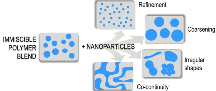
(39) Thèse de Xiang Yan, Université de Lille, 2019. polymers generating tremendous effective joints (Brown et al., 1993). Nevertheless, detachment problems can occur, as compatibilizers migrate from the interface at high shear rates. Furthermore, over the critical concentration, block copolymers saturate the interface, aggregate and afterward form micelles towards the bulk phases (Fortelný and Jůza, 2018). In addition, the incorporation of block copolymer of high Mw tends to localize in the bulk phases instead of the biphasic interface (Mural et al., 2018). Furthermore, the traditional compatibilizers are system-specific but not cost-effective to engineering (Si et al., 2006).. 1.5.2 (Nano)particles Compared with plasticizers, the use of inorganic fillers is less explored. With the development of nanotechnology, more and more commercialized and industrialized nanoparticles are being adopted to modify the microstructure of polymer blends. Lipatov (1995) revealed that in ternary systems, the free mixing energy ΔGm was modified as Equation 1-17.. Gm GAS GBS +GAB Equation 1-17. where A, B represent the polymer A, B, and S represent the (nano)particles, and the interacting pairs from the components are denoted in the subscripts of free energy ΔG. The addition of the nanofiller can possibly stabilize the binary systems, and the specific surface area of the fillers plays a dominant role, which should be taken into consideration for the selection of fillers (Ray et al., 2004). The rigid core from the particles localized at the biphasic interface exhibits Pickering effect, offering the morphology stability against shearing as well as annealing conditions (Wang et al., 2017b). The incorporation of (nano)particles will unavoidably impact the biphasic morphology, to which the localization of the fillers is a key factor. The resultant change can be refinement, coarsening, irregular shape or co-continuity shift. The scheme of the possible evolution of biphasic morphology influenced by the incorporation of 38. © 2019 Tous droits réservés.. lilliad.univ-lille.fr.
(40) Thèse de Xiang Yan, Université de Lille, 2019. nanoparticles are displayed in Figure 1-8 (de Luna and Filippone, 2016). As for the particles playing the role as a compatibilizer at the interface, the refinement effect is often expected to occur.. Figure 1-8 Scheme of the possible evolution of biphasic morphology influenced by the incorporation of nanoparticles (de Luna and Filippone, 2016).. Varieties of particles with distinct shapes and dimensions have been tested, such as spherical (silica nanoparticles (Huang et al., 2016), gold nanoparticles (Kwon et al., 2011), TiO2 (Li et al., 2009)), carbon black (Chen et al., 2017a), cage-like (POSS (Kodal, 2016)), patchy (graphene (Tong et al., 2017), clay (Mederic et al., 2018)) as well as one-dimensional (carbon nanotube (CNT) (Chen et al., 2017b) particles. The particles can play the role of not only compatibilizers but also functionalizers. Ginzburg (2010) summarized some examples of the particles and their functionalization, displayed in Table 1-2.. 39. © 2019 Tous droits réservés.. lilliad.univ-lille.fr.
Figure
+7
Documents relatifs
The present contribution is an extension to the finite strain regime of the Hybrid High-Order (HHO) method for incremental associative plasticity with small deformations [ 2 ]..
Nous exprimons la mesure de Mahler 2-supérieure et 3-supérieure de certaines fonctions rationnelles en terme de valeurs spéciales de la fonction zêta, de fonctions L et de
يعمالجا ميلعتلا مأ ،ماعلا ميلعتلا في تناكأ ءاوس ،ةيميلعت ةيلمع لك في ةدمعلأا مهأ دحأ اطلخا لاقلما اذه لجاعي يجاب ةعمابج اهبادآو ةيبرعلا ةغللا مسق في يجوغاديبلا ب راتمخ
Arg id Textual argument Formal argument a36 Consumers are in favour of plastic packagings P lastic_not_closed. that are not closed b P rotect_f lavor b ACC because they
A comprehensive database dedicated to cyanobacterial secondary metabolites facili- tates: (1) the detection and dereplication of known cyanobacterial toxins and secondary
( 2 ) - ك ،ةباتكلاب ّلاإ وتابثإ زكجي لا ؼرصتلا فاك فإف ؾلذ يف امب ؽرطلا ةفاكب وتابثلإ قيقحتلا ىلإ ػكعدلا ةلاحإ ـصخلا بمط ؾلذ عم ُي ؼرصتلا ّفأب اينم
L’archive ouverte pluridisciplinaire HAL, est destinée au dépôt et à la diffusion de documents scientifiques de niveau recherche, publiés ou non, émanant des
Quelque chose de partagé oui et puis avec des différences […] et puis une autre année c’était un spectacle qui s’est fait juste ici dans la salle de classe et puis : eux
