an author's https://oatao.univ-toulouse.fr/25926
https://doi.org/10.1109/LAWP.2013.2270942
El Hatmi, Fatiha and Grzeskowiak, Marjorie and Delcroix, David and Alves, Thierry and Protat, Stéphane and Mostarshedi, Shermila and Picon, Odile A multilayered coil antenna for ingestible capsule : near field magnetic induction link. (2013) IEEE Antennas and Wireless Propagation Letters, 12. 1118-1121. ISSN 1536-1225
A Multilayered Coil Antenna for Ingestible Capsule:
Near-Field Magnetic Induction Link
Fatiha El hatmi, Marjorie Grzeskowiak, David Delcroix, Thierry Alves, Stéphane Protat,
Shermila Mostarshedi, and Odile Picon, Member, IEEE
Abstract—A compact multilayered stacked ingestible coil
an-tenna is investigated for medical systems. The inductive link, comprising a 5-layer transmitter coil antenna and a 3-turn re-ceiver spiral coil, is modeled through a tissue-simulating liquid modeling the human body. The diameter and the thickness of the transmitter coil are respectively equal to 1 cm and 5 mm, while the dimensions of the receiver coil are equal to 7 8 cm . The variations of the position and the orientation of the capsule antenna are taken into account to evaluate the coupling response between the two magnetically coupled coils. We found that the inductive link presents an attractive option for improving the lifetime of ingestible capsules.
Index Terms—Magnetic induction link budget, multilayered
stacked coil antenna, on-body spiral coil antenna, wireless ingestible capsule.
I. INTRODUCTION
W
IRELESS ingestible capsule systems have garnered significant interest in medical applications and have been widely used in diagnoses and medical treatments of gastrointestinal (GI) tract diseases such as stomach and colon cancers [1]. The introduction of the noninvasive ingestible capsule in telemedicine is aimed at offering thorough coverage in terms of time and area [2] and thus at reducing pain and discomfort of the patient [3], [4]. The ingestible electronic capsule, which integrates sensors, batteries, transmission cir-cuit, antennas, and so on, is used for monitoring physiological parameters of the GI tract including temperature, pressure, pH, and oxygen concentration [2], [5], [6]. It can also provide the drug delivery to patients [7] or the internal image transmission of the GI tract through video capsule [4], [8]. The capsule must be small enough to be swallowed by patients. From the antenna designer’s perspective, it is crucial to consider some factors that affect the in-body antenna performances such as miniaturization and electrical properties of biological tissues as the link path is no longer air but human body.The magnetic field power falls off as the inverse sixth power of the distance [9], while the electromagnetic (EM) wave power drops off only with the inverse square of the distance. However,
The authors are with the ESYCOM Laboratory, Université Paris-Est Marne-la-Vallé, 77454 Marne-la-Vallé cedex 2, France (e-mail: [email protected]; [email protected]; [email protected]; [email protected]; [email protected]; [email protected]; [email protected]).
Digital Object Identifier 10.1109/LAWP.2013.2270942
the magnetic field depends on the relative permeability of the media, which is equal to one for biological tissues. Therefore, the magnetic field is not influenced by such media, unlike the electric field, which depends on the permittivity of the dissi-pative media. The radiation efficiency of a meandered capsule antenna is found to be equal to 0.1% in [8] and hardly reaches 0.9% for a spiral multilayered antennas in a 3-layer cylindrical body model [10]; this is due to the high permittivity of biolog-ical tissues, which leads to steep attenuation of the EM wave especially at high frequencies.
Magnetic induction is a promising alternative for capsule an-tennas operating inside the human body composed of various dissipative tissue layers.
Under a strict size limitation of the in-body systems, the mag-netic induction has been used to wirelessly transmit power to ingestible [3], [11] or implanted [12] antennas in order to avoid the use of batteries that limits the lifetime of such systems. The implanted antenna does not move inside the human body con-trarily to the ingestible capsule, which slides down into the GI tract. Hence, in wireless link modeling, it is necessary to take into account the position and orientation variations of the in-gestible capsule to guarantee maximum power transfer between the two magnetically coupled coils [13].
In this letter, an inductive link is established between a mul-tilayered stacked coil capsule antenna and a receiving on-body spiral coil. The capsule antenna generates an alternating mag-netic field at 40.68 MHz in the ISM band and is mutually cou-pled to the receiving on-body antenna located in its near field. Moreover, the orientation and the position of the moving cap-sule coil antenna are taken into account in the inductive link modeling.
II. COILANTENNADESIGN ANDMEASUREMENTSETUP
Several antenna parameters as well as the distance between the two coils representing the coupling elements of the wireless link govern the efficiency of the inductive link. The cou-pling response (1), given by the ratio of the received power to the transmitted power [14], depends on the quality factors
and and the efficiencies and of the transmitter and the receiver coils and the coupling coefficient between the two coils. The latter coefficient is a function of the distance be-tween the transmitter and the receiver and their respective coil radii and as presented in (2)
(1) (2)
Fig. 1. Transmitter and receiver coils: (a) multilayered capsule antenna struc-ture; (b) five layers of the capsule antenna arranged from left to right; (c) fabri-cated 5-layer capsule antenna; (d) fabrifabri-cated 3-turn receiver spiral coil.
where , , , and can be given as
(3) (4) and are the resistances of the transmitter and the receiver coils, and are the source and the load resis-tances, and are the inductances of the transmitter and the receiver coils that along with the mutual inductance give . The dimensions of the transmitter antenna, operating inside the GI tract, are limited by the size of the cap-sule in which it will be enclosed. Therefore, the in-body antenna diameter must be smaller than 10.1 mm, which corresponds to the capsule inner diameter [4]. To increase the magnetic field strength while reducing the dimensions of the in-body trans-mitter, the capsule antenna is chosen to be a multilayered coil. The advantages of the multilayered printed coil compared to the classic wired coil are essentially the robustness and the solidity. As it is depicted by Fig. 1(a)–(c), the structure of the capsule antenna is made of five turns printed on five stacked dielectric substrate separated by four superstrates. The thickness and the diameter of the substrate are 0.4 mm and 1 cm, respectively, while the thickness of the superstrate is 0.76 mm, and its diam-eter is equal to that of the substrate. The superstrate layers are used on the one hand to ensure a stable distance between the coil turns and on the other hand to make the antenna more solid. The built loop in every layer has a diameter of 9.5 mm and a line width of 1 mm to increase the quality factor of the transmitter coil. If the manufacturing process of the antenna allows metal-lized holes, the superstrate layers can be removed, and the total antenna height can be reduced from 5 to 2 mm. Hence, the turn number can be increased to guarantee maximum power transfer. The diameter of via hole used to connect each layer to the other is equal to 0.7 mm.
The fifth layer is connected to the feed terminal by a con-nector that runs through all substrates of the antenna. In order to increase the received power through the inductive link, the on-body receiver coil needs to have large dimensions, and its
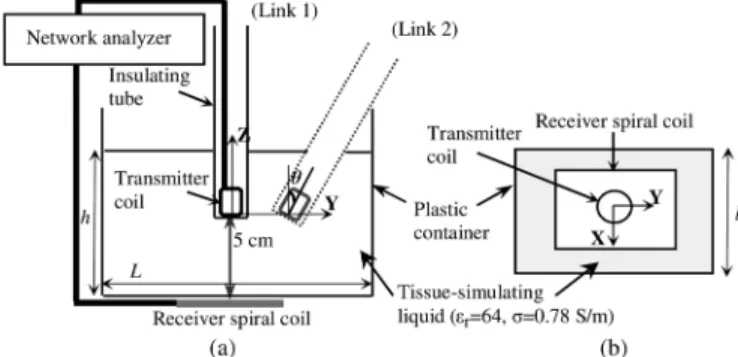
Fig. 2. Measurement setup: (a) side view; (b) top view.
input impedance must be matched with that of the transmitter coil. As it is shown by Fig. 1(d), the on-body antenna is a 3-turn spiral coil with outer size of 7 8 cm , a line width and spacing between lines of 1.5 mm, making it possible to increase the quality factor of the magnetic receiver coil. Both in-body and on-body coils are built, by mechanical etching, on the FR4 epoxy substrate with relative dielectric constant of 4.4, dielectric loss tangent of 0.02, and metallic thickness of 35 m. The substrate thickness of the receiver antenna is equal to 0.76 mm.
A matching circuit including one series capacitance followed by one parallel capacitance is used to match both coil input im-pedances close to 50 . The antennas are designed with the com-mercial simulator HFSS, and the structure is simulated in a ho-mogeneous tissue-simulating liquid available in our laboratory, which represents the human body, using its measured charac-teristics. The tissue-simulating liquid is characterized using the Agilent Dielectric Probe Kit, and the measured permittivity and conductivity at 40.68 MHz are equal to 64 and 0.78 S/m, respec-tively. Fig. 2 (Link 1: tube along ) summarizes the measure-ment setup of the inductive link; the in-body coil is in front of the on-body antenna, every coil being parallel to the -plane, and the path is along the -direction perpendicular to the antenna planes. The capsule antenna is isolated from the body liquid by a Plexiglass tube, whose diameter and thickness are respectively equal to 1.4 cm and 0.5 mm. As the small intestine is located at almost 5 cm from the surface of the skin [8], the transmitter an-tenna is placed 5 cm away from the receiver anan-tenna in the -di-rection including 4.6 cm of body liquid and 0.4 cm of air. This air gap between the receiver coil and the back side of the plastic container is due to the thickness of the SMA connector. The
di-mensions of the plastic container are cm
. The emitting and receiving coils are designed sepa-rately, and their respective matching networks are calculated.
When the inductive link is established, there is a coupling effect between the two coils: Both antenna input impedances are mismatched, and there is a frequency shift of a few hun-dred kilohertz. Therefore, the antenna matching networks have to be adjusted in order to get the resonant frequencies close to 40.68 MHz. As in the measurement setup, the capsule coil an-tenna is surrounded by air contained in the isolated tube; the input impedance and the operating frequency of the transmitting antenna immersed in the tissue-simulating liquid are slightly shifted compared to the free space. Therefore, when the trans-mission channel changes, the capacitances of the transmitter
Fig. 3. Simulated and measured coupling response , according to the fre-quency, between the capsule coil and the receiver coil separated by a distance of 5 cm when the path is the tissue-simulating liquid.
antenna do not vary; the series capacitance is equal to 180 pF, and the parallel capacitance is equal to 800 pF. However, the receiver antenna operates otherwise; the input impedance of the receiver coil changes dramatically when the transmission channel is no longer free space. Therefore, it is necessary to ad-just the capacitances of the receiver coil in each media. Hence, the series capacitance of the receiver coil is equal to 8.2 pF in free space and to 7.6 pF in the tissue-simulating liquid, while the parallel capacitance is equal to 213 pF in free space and 56 pF in the tissue-simulating liquid. Moreover, we had to use fer-rites to limit the influence of leakage current in the cable that connects the receiver coil to the network analyzer.
III. RESULTS(LINK1)
The measured input resistance of the receiver coil in-creases when the transmission channel changes from the
air to the tissue-simulating liquid ( and
). Thus, the quality factor decreases and becomes equal to 7.1 instead of 9.1 in the air. Moreover, the bandwidth of the receiver coil in the tissue-simulating liquid increases; the measured bandwidth is 0.2 MHz in the air, while 0.9 MHz in the tissue-simulating liquid. However, because the transmitter coil is inserted in the Plexiglass tube filled with air, the bandwidth of the capsule antenna hardly varies when the transmission channel changes and the measured bandwidth is around 0.47 MHz in both cases. Similarly, the quality factor of the capsule antenna does not change and remains around 0.61. From the plots of Fig. 3, it is observed that the simulated and the measured maximum transmission coefficient , which occur around 40.68 MHz in the tissue-simulating liquid, are equal to 18.1 and 20.7 dB, respectively. Thus, the difference between the simulated and the experimental results is 2.6 dB.
To evaluate the influence of the dissipative media on the re-ceived power, we measured the coupling response in the air; it is found to be equal to 16.8 dB at 40.68 MHz. Therefore, be-cause the in-body link uses the magnetic coupling between the coils, the difference between the maximum coupling response measured in the air and in the tissue-simulating liquid around 40.68 MHz is only equal to 3.9 dB. The data corresponding to the simulated and the measured antenna parameters, when the transmission channel is the tissue-simulating liquid, are listed in
TABLE I
MEASUREDIN-BODY ANDON-BODYANTENNASCHARACTERISTICS IN THE
PRESENCE OF THETISSUE-SIMULATINGLIQUID AT40.68 MHz
TABLE II
COUPLINGRESPONSEACCORDING TO THENUMBER OFLAYERS OF THE
TRANSMITTERCOIL IN THETISSUE-SIMULATINGMODELAROUND40.68 MHz
Table I. The quality factors and the efficiencies of the coils are deduced when the resistances and are set to 50 .
We also analyze the analytical link budget through the tissue-simulating model at 40.68 MHz based on the Agbinya–Masihpour model proposed in [14]. The antenna parameters are deducted from HFSS simulation (Table I) when and is set to 1 W. The coupling response in the tissue-simulating model obtained by analytical formula (1) at 40.68 MHz is equal to 14.2 dB, while it is found to be equal to 18.1 dB in simulation. Furthermore, before choosing the 5-layer structure, several simulations according to the number of layers of the transmitter coil were made in the tissue-simu-lating model to evaluate the effect of this parameter on the link budget. The data listed in Table II show the coupling response according to the number of layers and the corresponding quality
factor of the transmitter coil. Thus, when the
number of layers increases from 1 to 8, the response can be improved from 22.4 to 14.5 dB. It is important to note that for this parametric study, the dimensions of the 3-turn receiver antenna are 8 5 cm , its quality factor
is 44, and the distance between the two coils is set to 5.2 cm. Later in practice, we have slightly increased the width of the spiral coil (8 7 cm ) to improve the magnetic flux.
IV. CAPSULEANTENNAPOSITION ANDORIENTATION
VARIATION IN THETISSUE-SIMULATINGLIQUID(LINK2)
In Section III, the capsule coil was at 5 cm from the receiver antenna. In this paragraph, at first, we assume that the distance between the two coils in the -direction varies. Fig. 4 shows the parameter between the ingested and the on-body coils when the transmission channel is the tissue-simulating liquid and the distance increases from 1 to 8 cm. The measured coupling re-sponse varies between 9 and 27.5 dB, and there is a marginal drop that varies from 1 to 2.6 dB between the simulated and the experimental results.
As the swallowable capsule slides down into the GI tract, an effective inductive link can only be established if the receiver on-body coil detects the transmitted signal regardless of the transmitter position and orientation. The purpose of the second study in this paragraph is to verify that the received signal re-mains at an acceptable level when the capsule antenna is located
Fig. 4. Simulated and measured coupling response around 40.68 MHz in the tissue-simulating liquid between the two coils according to the -distance.
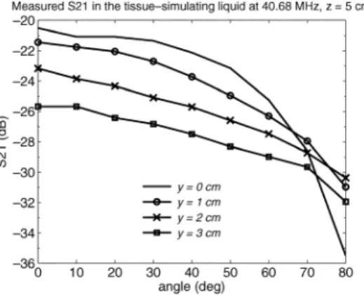
Fig. 5. Measured parameter around 40.68 MHz in the tissue-simulating liquid according to the angle at different -positions when cm.
randomly. In this way, we varied the position of the ingestible antenna along the -axis and then, for every -position, we changed the angle of the transmitter coil from 0 to 80 in the -plane while keeping the -distance constant and equal to 5 cm as it is shown by Fig. 2 (Link 2).
It is not possible to reach the angle of 90 because the in-body antenna is not enclosed in the capsule and the tissue-simulating liquid could flow into the isolated tube in this orientation. The plastic container dimensions in this case are equal to
cm to allow a maximum variation of the angle by
reducing the height of the container. The experimental results presenting the parameter according to the angle, where the -position is equal to 0, 1, 2, and 3 cm, are depicted by Fig. 5. It is clear from these plots that the maximum received signal level for each -position occurs when . This configura-tion is the most optimal because the H-field lines perpendicular to the on-body antenna surface are maximal. We can also con-clude that for every capsule antenna position, the parameter decreases when the angle increases. Hence, the response always varies between 20.5 and 35.5 dB; if a threshold of 35 dB is fixed, we can say that the received signal remains efficient regardless of the orientation and the position of the in-gested coil.
V. CONCLUSION
In wireless ingestible capsule systems, magnetic induction is a promising alternative technique because the path loss depends
on the permeability of biological tissues, which is equal to that of the air. Although the magnetic field power falls off as the in-verse sixth power of the distance, magnetic induction technique has been adopted in this letter to design a short-range wireless link through a tissue-simulating liquid since the dielectric prop-erties of biological tissues do not perturb the magnetic field. Through HFSS simulation that is validated by measurements, the proposed multilayered stacked coil antenna is shown to be suitable as a compact robust ingestible transmitter. An analytical model is also applied to evaluate the factors affecting the link budget. The measured coupling response of the system, which depends on the position and the orientation of the capsule an-tenna, remains effective and varies between 20.5 dB (0.89%) and 35.5 dB (0.03%) in the tissue-simulating liquid.
As the capsule antenna should transmit physiological param-eter data, it is necessary to design a receiver coil antenna array to find the accurate position of this data source inside the GI tract. It will be the future work of this study.
REFERENCES
[1] M. Q.-H. Meng, T. Mei, J. Pu, C. Hu, X. Wang, and Y. Chan, “Wireless robotic capsule endoscopy: State-of-the-art and challenges,” in Proc.
5th WCICA, Jun. 15–19, 2004, vol. 6, pp. 5561–5565.
[2] L. Wang, T. D. Drysdale, and D. R. S. Cumming, “In situ characteri-zation of two wireless transmission schemes for ingestible capsules,”
IEEE Trans. Biomed. Eng., vol. 54, no. 11, pp. 2020–2027, Nov. 2007.
[3] Y. Guozheng, H. Biao, and P. Zan, “Design of battery-less and real-time telemetry system for gastrointestinal applications,” in Proc. IEEE
Int. Conf. Control Autom., May 30–Jun. 1 2007, pp. 245–249.
[4] S. H. Lee and Y. J. Yoon, “Fat arm spiral antenna for wideband cap-sule endoscope systems,” in Proc. IEEE RWS, Jan. 10–14, 2010, pp. 579–582.
[5] N. Aydin, T. Arslan, and D. R. S. Cumming, “Design and implemen-tation of a spread spectrum based communication system for an in-gestible capsule,” in Proc. 24th EMBS/BMES Conf., 2002, vol. 2, pp. 1773–1774.
[6] H. Cao, V. Landge, U. Tata, Y.-S. Seo, S. Rao, S.-J. Tang, H. F. Tib-bals, S. Spechler, and J. Chiao, “An implantable, batteryless, and wire-less capsule with integrated impedance and pH sensors for gastroe-sophageal reflux monitoring,” IEEE Trans. Biomed. Eng., vol. 59, no. 11, pp. 3131–3139, Nov. 2012.
[7] H. Rajagopalan and Y. Rahmat-Samii, “Novel ingestible capsule an-tenna designs for medical monitoring and diagnostics,” in Proc. 4th
EuCAP, Apr. 12–16, 2010, pp. 1–5.
[8] H. Rajagopalan and Y. Rahmat-Samii, “Link budget analysis and char-acterization for ingestible capsule antenna,” in Proc. iWAT, Mar. 1–3, 2010, pp. 1–4.
[9] J. I. Agbinya, N. Selvaraj, A. Ollett, S. Ibos, Y. Ooi-Sanchez, M. Brennan, and Z. Chaczko, “Size and characteristics of the “cone of silence” in near-field magnetic induction communications,” J.
Battlefield Technol., vol. 13, no. 1, pp. 1–4, Mar. 2010.
[10] F. Merli, L. Bolomey, J. Zurcher, G. Corradini, E. Meurville, and A. K. Skriverviky, “Design, realization and measurements of a miniature an-tenna for implantable wireless communication systems,” IEEE Trans.
Antennas Propag., vol. 59, no. 10, pp. 3544–3555, Oct. 2011.
[11] Y. Kobayashi, K. Ishida, K. Okada, K. Masu, and Y. Horiike, “A bat-teryless wireless communication circuit for measurement of gastric acid,” in Proc. IEEE BioCAS, Nov. 29–Dec. 1 2006, pp. 5–8. [12] A. C. Tikka, M. Faulkner, S. Al-Sarawi, and Y. Horiike, “Secure
wireless powering and interrogation of an implantable microvalve,” in
Proc. IEEE Top. Conf. BioWireleSS, Jan. 16–19, 2011, pp. 35–38.
[13] F. El Hatmi, M. Grzeskowiak, S. Protat, and O. Picon, “Link budget of magnetic antennas for ingestible capsule at 40 MHz,” Prog.
Electro-magn. Res., vol. 134, pp. 111–131, 2013.
[14] J. I. Agbinya and M. Masihpour, “Near field magnetic induction communication link budget: Agbinya-Masihpour model,” in Proc. 5th