HAL Id: hal-00877475
https://hal.archives-ouvertes.fr/hal-00877475v2
Submitted on 21 Oct 2015
HAL is a multi-disciplinary open access
archive for the deposit and dissemination of
sci-entific research documents, whether they are
pub-lished or not. The documents may come from
teaching and research institutions in France or
abroad, or from public or private research centers.
L’archive ouverte pluridisciplinaire HAL, est
destinée au dépôt et à la diffusion de documents
scientifiques de niveau recherche, publiés ou non,
émanant des établissements d’enseignement et de
recherche français ou étrangers, des laboratoires
publics ou privés.
programming
Emmanuel Vinot, Rochdi Trigui, Yuan Cheng, Christophe Espanet, Alain
Bouscayrol, Vincent Reinbold
To cite this version:
Emmanuel Vinot, Rochdi Trigui, Yuan Cheng, Christophe Espanet, Alain Bouscayrol, et al..
Improvement of an EVT-based HEV using dynamic programming.
IEEE Transactions on
Ve-hicular Technology, Institute of Electrical and Electronics Engineers, 2014, 63 (1), pp.
40-50.
�10.1109/TVT.2013.2271646�. �hal-00877475v2�
1
Improvement of an EVT-based HEV using
dynamic programming
Emmanuel Vinot , Rochdi Trigui, Member, IEEE,
Yuan Cheng,
Christophe Espanet, Member, IEEE, Alain Bouscayrol, Member, IEEE, Vincent Reinbold.
Abstract- Automotive engineers and researchers haveproposed different Series-Parallel Hybrid Electric Vehicle SP-HEV topologies. The Toyota Hybrid System (THS) is the most known SP-HEV based vehicle, but alternative solutions such as Electric Variable Transmission (EVT) have been also proposed. Efficient comparison between these different solutions is a key point in order to estimate the added value of each topology. This paper presents the application of optimal control to two series-parallel hybrid architectures for efficiency assessment purpose. The dynamic programming method is applied to the THS as well as to a virtual hybrid vehicle with an EVT. The way to take into account the supplementary degree of freedom provided by the decoupling of wheels and engine in both topologies is presented. The optimal fuel consumptions are then compared on different driving cycles and bring out an over consumption of the EVT topology. Then, a parametric study shows that inserting an appropriate gear ratio on the ICE shaft can improve the EVT efficiency that becomes close to the THS efficiency.
Index Terms – series-parallel, hybrid vehicle, dynamic programming, electrical variable transmission
I. INTRODUCTION
Hybrid Electric Vehicles (HEVs) are one of the effective solutions chosen by the automotive industry to reduce CO2
and pollutant emissions. By using a combination of an ICE and electrical machines supplied by batteries, the efficiency of the vehicle is enhanced. Among the different hybrid power-train architectures, full hybrid series-parallel architectures (SP-HEVs) are one of the more advanced solutions to reduce fuel consumption [1]-[3]. Such architectures allow splitting the power flow in a combined series and parallel way.
Moreover, this kind of topology provides a possible decoupling of the wheel and the engine speed. Therefore a supplementary degree of freedom can be used to optimize the engine operating points.
The series-parallel power split vehicle Toyota Prius was the first SP-HEV with worldwide diffusion and remains until now a reference for automotive hybridization [4], [6]. However other advanced SP-HEVs like the Electric Variable Transmission (EVT) have been proposed in the literature but without efficiency comparison with the existing SP-HEVs. This topology enables theoretically the same functionalities as the THS but in a more compact way [7]-[11].
The EVT has been studied and documented especially in a design purpose [11]-[14]. Two main topologies are usually described using two electrical machines or one double rotor integrated machine. A sizing and design approach aiming to replace the THS transmission by an EVT has been proposed in [11]. This study showed that the specifications of the maximum torque and power of the electrical machines are more or less the same in both SP-HEVs, namely THS and EVT.
The efficiency assessment of such complex systems is not an easy task. One of the key issues is the energy management because it has an important impact on the fuel economy results. The rule-based THS management has been discussed in previous publications [15], [16]. The same kind of strategy has been adapted to EVT [11], [17]. However, in order to compare the HEVs in their best fuel consumption it is not appropriate to apply rule based control methods because the results strongly depend on the control tuning [18].
An optimal control method has been developed to perform a comparison of both topologies [19]. Using a system modelling approach, the dynamic programming method already applied to THS [4], [20], [21] has been extended to EVT. It shows that under the assumption of using the same components, EVT fuel consumption is 10 % higher than THS’s. An energetic analysis has been performed and shows that the main difference appears in the losses of the electrical machine EM2. It shows that the EM2 linked to the engine in EVT mainly operates in a high torque and low speed area with low efficiency. This paper investigates the possibility of inserting a gear on the engine shaft to change the EM2 operating area.
First the SP-HEV principle is presented in section II. A reminder on dynamic programming and its application on SP-HEVs is then presented in section III. The method to choose the engine operating point is detailed for each topology. In
Copyright (c) 2013 IEEE. Personal use of this material is permitted. However, permission to use this material for any other purposes must be obtained from the IEEE by sending a request to pubs-permissions@ieee.org.
E.Vinot, R. Trigui and V.Reinbold are with the Transport and Environment Laboratory, French Institut of Science and Technology for Transport, Developpement and networks, 69675, Bron, France (e-mail: Emmanuel.vinot@ifsttar.fr).
Yuan Cheng and A. Bouscayrol are with the Laboratory of Electrotechnics and Power Electronics, University of Lille 1, 59655 Villeneuve d’Ascq, France (e-mail: chengyuan_hit@yaho.com.cn, Alain.Bouscayrol@univ-lille1.fr)
Christophe Espanet is with the Institut Franche-Comté Électronique, Mécanique, Thermique et Optique-Sciences et Technologies, Energie et Ingénierie des Systèmes Multiphysiques, University of Franche-Comte, 90010 Belfort Cedex, France (email: christophe.espanet@univ-fcomte.fr).
All authors are also with the MEGEVH, French National Network on HEVs, France, http://www.univ-lille1.fr/megevh.
2 section IV, the comparison between THS and EVT is then presented. Finally a new EVT solution with gear shows that the fuel consumption of this architecture can be reduced to the level of THS.
II. SERIES PARALLEL HEV
A. General principle
In conventional vehicles it is of high importance to have a device that enables the change of the ratio between engine and wheel speed. This is generally performed by a gearbox and a clutch, and sometimes, a mechanical Continuous Variable Transmission is used in order to choose the engine operating point independently of the wheel speed.
In hybrid vehicles the use of electrical machines, by transmitting the power flow electromagnetically allows to decouple the engine and wheel speeds. A part of the power flow is thus an electrical series flow (Fig. 1). A well known way to split the engine flow is a mechanical coupling using a planetary gear as in the Toyota Hybrid Systems (section II.B).
Another solution called Electrical Variable Transmission (EVT) is to split the power flow using an electrical machine with rotating stator and rotor (section II.C).
ICE
Battery FG
Engine power flow Series power flow Parallel power flow
electrical power flow
Fig. 1 : global scheme of SP-HEVs
B. Mechanical variable solution : the Toyota hybrid system
The Toyota hybrid system is the most known SP-HEV architecture. It is composed of one electrical machine EM1 linked to the wheel (Fig. 2) allowing the electrical mode. A planetary gear linked to the engine and the second electrical machine EM2 insures the splitting functionality. It is a relatively simple transmission considering that no gear box and no clutch are used. One drawback is that in electrical mode the planetary gear ring and thus the EM2 has to be in rotation. Moreover the EM2 speed can frequently be high (near 10000 rpm [4]). This implies high losses in the machine, and sometimes, it can constrain the engine operation [4]. ICE EM1 INV2 Battery FG EM2 INV1 PG
Engine power flow Series power flow Parallel power flow
Fig. 2 : THS architecture
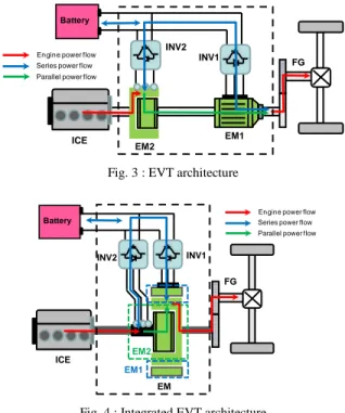
C. Electrical variable transmission
The EVT (Fig. 3) is an interesting solution as it only uses electrical machines to split the engine power flow. A solution is to link the external armature of the EM2 machine to the engine shaft and its rotor to the wheel. Thus a rotating external armature has to be used and fed by power electronics. The EM2 speed (difference between engine and wheel speed) will determine the amount of energy split from the electrical network.
As in THS the EM1 machine is linked to the final gear and will insure the electrical mode.
A more compact topology (Fig. 4) can be made with only one double rotor electrical machine [17] to ensure the split functionality. In a functional point of view the two topologies behave exactly in the same way.
ICE EM1 INV2 Battery FG EM2 INV1
Engine power flow Series power flow Parallel power flow
Fig. 3 : EVT architecture
Engine power flow Series power flow Parallel power flow
ICE INV2 Battery FG INV1 EM EM2 EM1
Fig. 4 : Integrated EVT architecture
III. DYNAMIC PROGRAMMING APPLIED TO SP-HEV Optimal management methods are a good way to compare the fuel consumption of hybrid architectures [21], [23] and thus improve the systems. In this paper the Dynamic Programming method has been used to compare the optimal fuel consumption of THS and EVT.
A. The Dynamic Programming applied to hybrid vehicles
Dynamic Programming is frequently applied to hybrid vehicles to minimize the off-line fuel consumption (or more complex criterion) on an a priori known driving cycle [20], [21].
In general, the optimization is based on a systemic approach and energetic models of different subsystems (section III.B).
In our study, optimization methods are applied using a backward approach [4] which needs the knowledge of the driving cycle and the vehicle characteristics (inertia and
3 resistant forces) and goes upstream from the wheels to battery and engine.
In the case of SP-HEVs the optimal control has to determine:
- the share of power between batteries and engine, i.e the electric or hybrid mode and the amount of electric power in hybrid mode (section II.A.1)
- the engine operating point, i.e. the engine speed and torque to maximize the overall system efficiency (section II.B.2).
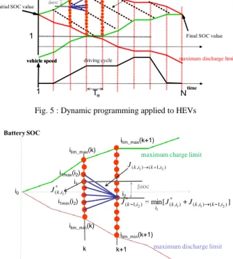
To apply the dynamic programming method to hybrid vehicles, a battery state of charge (SOC) vs. time area is considered (Fig. 5). The SOC is the state variable and the battery current (Ibat) is the control variable. The area is
meshed in time and SOC samples. The time is sampled in N steps of te, the SOC is sample in M steps between minimum
and maximum SOC value, SOCmin and SOCmax.
The principle is to find the optimal battery state of charge trajectory which minimizes the fuel consumption along a known in advance driving cycle.
The points of two consecutive columns are linked by oriented edges associated with a fuel consumption. This fuel consumption depends on the driving cycle conditions and the SOC variation between the two points of an edge.
A fuel consumption objective J can be considered during a driving cycle of N samples of time te:
N SOC k J J 1 ) , ( (1)
where J(k, soc) is the instantaneous fuel rate for a given
battery current and a given speed and torque of the wheels. The minimum of J is obtained for the optimal trajectory of SOC using Bellman principle [22].
Considering a given battery current from one SOC point to another, the fuel consumption on the edge between these two points has to be calculated using the vehicle model (section III.B). The battery current is easily calculated (2) using the SOC variation between the beginning and the end of the edge soc,
e f bat SOC bat t C I 100 3600 (2)
where Cbat is the battery capacity in Amps.hours, and f is the
faradic efficiency.
The SOC constraint imposing the final SOC is respected by the graph construction (Fig. 5). Using the maximum battery charge and discharge possibilities, the studying area is built to bring the SOC from its initial value to its final desire value.
The maximum charge and discharge current is calculated using the system’s model. For example, in all electric mode, the battery current is calculated in a backward direction from wheels to battery. If the necessary current is too high, electric mode is not possible and maximum battery continuous current limits the discharge current.
To solve this problem recurrent iterative methods using Bellman principle [22] are currently used (Fig. 6).
At each point of a column i2, the following equation is
solved iteratively, starting at point (1, i0) with a fuel
consumptionJ(*1,i0) 0: ) 1 ( ) 1 ( ] [ min ] , [ max lim_ min lim_ 2 * ) , ( ) , 1 ( ) , ( ) ( ) ( 1 * ) , 1 ( 2 1 2 max 1 2 min 1 1 2 k i k i i for J J i J ki k i ki i i i i i i k i (3)
where J((k,i1) (k+1,i2)) is the instantaneous fuel
consumption from a point of index (k,i1) to a point of index
(k+1,i2). For instance, we assume that it depends only on the
SOC variation and vehicle speed (section II.B).
* ) , (ki1
J is the minimum fuel consumption from the beginning (time 0) to point (k,i1) i.e at time k for a state
SOC(i1).
Knowing the best trajectory, the control variable (Ibat) is
easily deduced from the SOC evolution (2) and other variables (engine torque and speed, electrical motor torque and speed…) are then deduced from the system model.
Battery SOC
vehicle speed
time
Final SOC value Initial SOC value
maximum charge limit
maximum discharge limit
To be meshed area
driving cycle
Battery SOC
vehicle speed
edge : cost=J(k, soc)
soc
1 Te N
1 M
Fig. 5 : Dynamic programming applied to HEVs
Battery SOC
maximum charge limit
maximum discharge limit
k k+1 i1 i2 ilim_min(k+1) ilim_max(k+1) ilim_max(k) ilim_min(k) soc i0 ) , 1 ( ) , (ki1 k i2 J * ) , (ki1 J ] [ min (*,) (,) ( 1, ) * ) , 1 ( 1 1 2 1 2 i ki ki k i i k J J J i1min(i2) i1max(i2)
Fig. 6 : Dynamic programming solving method
The dynamic programming method described above can be applied to any HEV topology. In the case of SP-HEVs, an additional degree of freedom has to be considered. For a given battery current Ibat and wheel torque and speed (Tr and r), a choice has to be previously done on the engine
operating point to maximize the overall system efficiency as presented in the following section.
4
B. Case of SP-HEV
1. Mechanical and electrical relations in THS and EVT
This section presents the cost calculation on a given edge in the case of the THS (Fig. 7) and the EVT (Fig. 8).
The vehicle model is based on the VEHLIB library model [15]. The electrical machines and the inverters are modelled with efficiency maps and the engine with fuel consumption maps. The battery model consists of an equivalent electric circuit with an open circuit voltage Ebat, an internal serial
resistance Rbat, and a faradic efficiency f. Ebat depends on the
SOC and the temperature, f depends on the SOC and the
current sign and Rbat depends on the SOC, the temperature
and the current sign, all using look up tables obtained by experiments.
The temperature is fixed for all the driving cycle but is chosen at the beginning of the cycle. Nevertheless, no thermal model is used, and the parameters remain constant vs. temperature during all the driving cycle.
Battery 0 Strategy Vs Chassis model 020004000600080001000012000 -80 -60 -40 -20 0 20 40 60 80
Regime moteur electrique en Tr/mn
Couple sur l arbre en Nm
46 46 4660 60 60 60 60 72 72 72 72 72 81 81 81 8181 81 86 86 86 86 86 86 90 90 90 90 90 92 92 0100020003000400050006000 -20 0 20 40 60 80 100 120 140
Regime moteur thermique en Tr/mn
Couple sur l arbre en Nm
250 275 275 275 300 300 300 400 400 400 Axle + gear 020004000600080001000012000 -80 -60 -40 -20 0 20 40 60 80
Regime moteur electrique en Tr/mn
Couple sur l arbre en Nm
46 46 4660 60 60 60 60 72 72 72 72 72 81 81 81 8181 81 86 86 86 86 86 86 90 90 90 90 90 92 92 J(Tice, ice) Ibat I em1 Iem2 Tr, r Tem1, ring Tring, ring Tice, ice Tem2, em2 SOC Planetary gear EM2 EM1 ICE Ubat Ebat IbattRbat
Fig. 7 : Backward approach of THS architecture
0 Strategy Vs Chassis model 020004000600080001000012000 -80 -60 -40 -20 0 20 40 60 80
Regime moteur electrique en Tr/mn
Couple sur l arbre en Nm
46 46 4660 60 60 60 60 72 72 72 72 72 81 81 8181 8181 86 86 86 86 86 86 90 90 90 90 90 92 92 0100020003000400050006000 -20 0 20 40 60 80 100 120 140
Regime moteur thermique en Tr/mn
Couple sur l arbre en Nm
250 275 275 275 300 300 300 400 400 400 Axle + gear 020004000600080001000012000 -80 -60 -40 -20 0 20 40 60 80
Regime moteur electrique en Tr/mn
Couple sur l arbre en Nm
46 46 4660 60 60 60 60 72 72 72 72 72 81 81 81 8181 81 86 86 86 86 86 86 90 90 90 90 90 92 92 J(Tice, ice) Ibat Iem1 Iem2 Tr, r Tem1, em1 Tice, ice Tem2, em2 SOC
ICE EM2 EM1
r r T Battery Ubat Ebat IbattRbat
Fig. 8 : Backward approach of EVT architecture
ICE EM2 EM1
PG ring planet carrier
sun
Tring Tring+ Tem1
Fig. 9 Planetary gear connections
On each edge of the graph, Ibat, Tr and r are known. The
equation of each components of the system has then to be used to calculate the engine operating point and thus its fuel consumption on a backward manner.
From the wheel torque and speed constraints (Tr, r), one
can easily deduce that
f r veh r T dt d J T (4)
where Tr is the wheel torque, Tf is the load torque calculated
from the resistant forces, Jveh is the overall inertia of the
vehicle brought back to the wheels and r is the wheel speed.
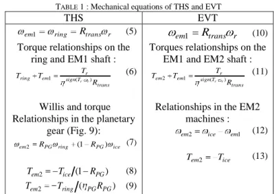
TABLE 1 presents the equations for the two architectures.
Tring is the torque on the planetary gear ring, Tem1 is the torque
on the EM1 shaft, is the efficiency of the transmission (axle plus gear), Rtrans is the transmission ratio, Sign(Tr, r) is the
sign of the wheel power. Thus the wheel torque is divided or multiplied by the gear efficiency depending on the direction of the wheel power. Tice is the ICE torque and PG is the
efficiency of the planetary gear. Tem2 is the torque on the
EM2 machine shaft.
em1, em2, ring and ice are respectively the speeds of the
electrical machines EM1 and EM2, planetary ring and engine. RPG is the planetary gear ratio
(RPG=-Nteeth_ring/Nteeth_sun), with Nteeth_ring and Nteeth_sun the
teeth number of the ring and sun gears.
The splitting power functionality is performed by the EM2 machine and the planetary gear in THS (7) to (9).
In EVT, EM2 torque strikes ICE torque (13). The EM2 rotor speed is the same as EM1 speed and the stator speed corresponds to the ICE speed. The difference between this two speeds (12) imposes the power derived by electrical network.
TABLE 1 : Mechanical equations of THS and EVT
THS EVT
r trans ring
em1 R (5)
Torque relationships on the ring and EM1 shaft :
trans T sign r em ring R T T T r r ) ( 1 (6)
Willis and torque Relationships in the planetary
gear (Fig. 9): ice PG ring PG em2 R (1 R ) (7) ) 1 ( 2 ice PG em T R T (8) ) ( 2 ring PG PG em T R T (9) r trans em1
R
(10) Torques relationships on theEM1 and EM2 shaft :
trans T sign r em em R T T T r r ) ( 1 2 (11)
Relationships in the EM2 machines : 1 2 ice em em (12) ice em T T 2 (13)
The electrical network is the same in both architectures. The electrical node between the electrical machines and the battery gives:
.
0
2 1 em acc bat emI
I
I
I
(14)The relations concerning the electrical machines are obtained by losses map model:
)
,
(
)
(
E
batR
batI
batI
em1T
em1 em1Pt
em1T
em1 em1 (15))
,
(
)
(
E
batR
batI
batI
em2T
em2 em2Pt
em2T
em2 em2 (16) where Iem1, Iem2, Iacc and Ibat are respectively the DC current inelectrical inverters of the EM1 and EM2 electrical machines (considered as receptors), in the accessories and in battery (considered as a generator). Note the current in the accessories corresponds to a constant value of power consumed in accessories and is fixed to 250 W.
5
Ptem1 and Ptem2 are the losses in the electrical machines
and inverters, E is the open battery voltage and R is the internal battery resistance which depends only on SOC and the battery current.
The problem is then to solve the SP-HEV systems equations.
2. Choice of engine operating point
In THS considering (6) to (9) and (14) to (16), and Ibat
imposed by the strategy we obtain 7 equations and 8 unknown variables ( em2, ice, Tem2, Tice, Tring, Tem1, Iem2, Iem1).
That means that there is one degree of freedom. This degree of freedom allows choosing, for example, the engine speed to minimize the fuel consumption for a given edge (Ibat, Tr and
r imposed).
In EVT the system is described by 6 equations (11) to (13) and (14) to (16) and 7 unknown variables ( em2, ice,
Tice, Tem2, Tem1, Iem2, Iem1), it means that, as in the THS, there is
also one degree of freedom.
In both architectures, the engine speed is chosen as the variable to be fixed.
A possible solution to fix this degree of freedom is to use a pre-determined engine torque versus speed curve [23]. This is the way used to develop the online rule-based management of the Prius-II [15] and the used curve is presented in (Fig. 10), which allows operating the engine in an efficient specific area. Nevertheless, the best engine specific consumption is not obviously the best system operating point taking into account the electrical machine losses [19]. Thus it does not correspond to the minimum possible fuel consumption. Moreover a pre-defined curve may be a good solution for THS but not for EVT.
225 225 235 235 235 245 245 270 270 300 300 400 400 600 600 500 1000 1500 2000 2500 3000 3500 4000 4500 5000 0 20 40 60 80 100 Engine revolution in rpm Ef fe c ti v e t o rq u e i n N m Specific Consumption in g.KWh Pre-defined engine operating curve
Fig. 10 : Pre-defined engine operating curve in Toyota Prius-II.
Taking the previous remarks into consideration, it is proposed to search in each edge the engine operating point which minimizes the fuel consumption. In fact, the electrical machines operations, and thus their efficiency, is highly dependant on the engine torque and speed. Thus the best system global efficiency has to be found.
To achieve that, in the simulation algorithm, ice is
sampled from 0 to its maximum value. For each value of ice
the non-linear systems (4) to (10) are solved to find the engine torque Tice and thus the fuel consumption. It means
that on each edge of the graph for each value of ice the
engine torque which solves the systems has to be calculated. A good way to solve the system with a minimum computer effort is to sample the engine torque between 0 and
its maximum value for a given speed. Then the battery power
Pbat_syst obtained for each engine torque and speed couple is
calculated and compared to the battery power Pbat calculated
using the edge soc variation:
acc em em syst bat P P P P _ 1 2 (17)
where Pem1 and Pem2 are the electrical power of the electrical
machines and inverters, and Pacc the accessories power.
Knowing that the electrical machine power is the sum of mechanical power and losses, it leads to:
.
)
,
(
)
,
(
2 2 2 2 2 1 1 1 1 1 _ acc em em em em em em em em em em syst batP
T
Pt
T
T
Pt
T
P
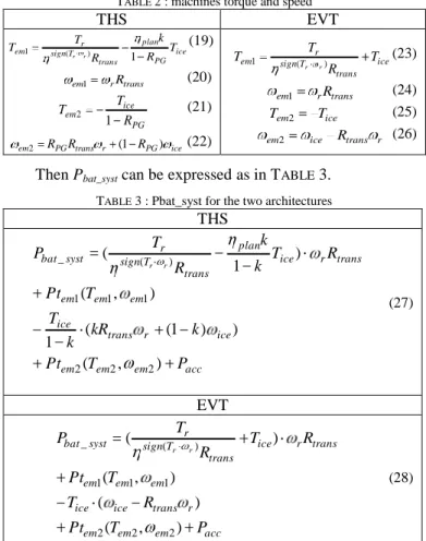
(18)Thus using (5) to (13) Tem1, em1,Tem2 and em2, can be
expressed depending on Tice , ice and known parameters ( r
and Tr), TABLE 2.
TABLE 2 : machines torque and speed
THS EVT ice PG plan trans T sign r em T R k R T T r r ) 1 ( 1 (19) trans r em1 R (20) PG ice em R T T 1 2 (21) ice PG r trans PG em2 R R (1 R ) (22) ice trans T sign r em T R T T r r ) ( 1 (23) trans r em1 R (24) ice em T T 2 (25) r trans ice em2 R (26)
Then Pbat_syst can be expressed as in TABLE 3.
TABLE 3 : Pbat_syst for the two architectures
THS acc em em em ice r trans ice em em em trans r ice plan trans T sign r syst bat P T Pt k kR k T T Pt R T k k R T P r r ) , ( ) ) 1 ( ( 1 ) , ( ) 1 ( 2 2 2 1 1 1 ) ( _ (27) EVT acc em em em r trans ice ice em em em trans r ice trans T sign r syst bat P T Pt R T T Pt R T R T P r r ) , ( ) ( ) , ( ) ( 2 2 2 1 1 1 ) ( _ (28)
On a given edge, soc and thus Ibat are known. Ubat is
easily calculated using battery model. Solving the system consists then in finding Tice such as Pbat_syst= Pbat=IbatUbat.
Looking at the evolution of the battery power balance
Pbat_syst - Pbat versus Tice (Fig. 11), a linear interpolation is
performed between the nearest positive and negative value to zero. Thus the engine torque value is calculated for each engine speed and the corresponding fuel consumption is deduced. The engine speed with the lowest fuel consumption is finally selected as the final cost of the edge.
6 It has been observed that sampling the ICE Torque by step of 5 N.m gives good results. No significant changes have been observed in the global fuel consumption or strategy by increasing this precision.
0 20 40 60 80 100 -1.5 -1 -0.5 0 0.5 1x 10 4 P b a ts y s t-P b a t in W linear interpollation P b a t_ s y s t-P b a ti n W ICE torque in N.m Fig. 11 : Battery power balance.
IV.COMPARISON BETWEEN THS AND EVT
The purpose of this section is to present a comparison between THS and EVT. A first comparison is focused on the weight and volume of both topologies. A second comparison is focused on the fuel consumption for the same drive cycle. It should be noticed that THS-II is an existing optimized system implemented on commercial vehicles. On the opposite EVT characteristics are issued from a preliminary study which could be improve in future developments.
The data for the THS comes from different characterizations studies [15], [24], [25]. The data from the EVT is issued from previous works using the Finite Element method software [12]. The component specifications of the Prius-II are presented in TABLE 4.
A. Comparison elements on weight and volume
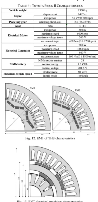
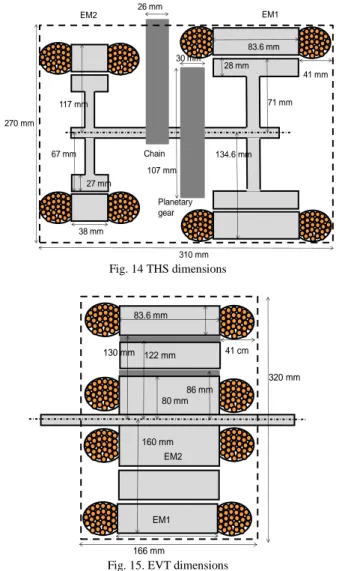
Fig. 12 and Fig. 13 present the cross sections of the two machines of THS and of the EVT. Fig. 14 and Fig. 15 present axial cross sections of the two systems in order to compare the overall occupied volume. TABLE 5 presents elements of weight and volume neglecting the housing of the systems. The planetary gear volume and weight have been approximately estimated.
Previous studies show that the specifications of the maximum torque and the power of the electrical machine are more or less the same in the two topologies [11]. The length of EM1 of THS and EVT are the same as well as linear current density. To provide the same maximum torque on EM1 (400 Nm) the EVT external diameter is bigger as it uses surface mounted magnets instead of buried magnets as in THS. The THS air-gap field is thus higher. It also presents a high reluctant torque in addition to the electromagnetic torque. The length of the EVT EM2 machine is higher than that of THS as it is inside the EM1 machine. It is also noted that the slot of the inside EM2 machine, and consequently the copper volume, is high to avoid cooling problems of the inner rotor.
The work reported in [11] concentrates on the design of a functional EVT that fits the needed specifications. The optimization of this device is in the perspective of the study. However, the designed EVT already presents relatively good
characteristics compared to those of the THS in terms of weight and volume. For the moment, the results give an advantage of approximately 8 % of weight to the THS while the volume of THS is 20 % higher than the EVT system.
The EVT can be improved and become more compact. For example, buried magnets can be used instead of surface-mounted magnets. Also, the copper volume may be reduced especially in the inner rotor. The global design of the system can also be improved using a more global sizing approach [26].This approach has to optimize the size of the different components with different gear ratios, together with the optimization of the energy management parameters [27],[28]. A global optimization algorithm, including optimal energy management, can be used to calculate the fuel consumption objective. This approach is already in progress on another kind of HEV in the laboratories of the authors [29].
TABLE 4 :TOYOTA PRIUS-IICHARACTERISTICSPrius 2004
Vehicle weight 1360 kg
displacement 1497 cc
max power 57 kW@5000rpm
Planetary gear ratio(ring,planet,sun) 2.6 (78/23/30)
Gear ratio 4.113
max power 50 kW
maximum speed 6000 rpm
maximum voltage in use 500 V maximum torque 400 Nm (0 à 1200 rpm)
max power 30 kW
maximum speed 10000 rpm
maximum voltage in use 500 V maximum torque 160 Nm(0 à 1800 tr/min)
NiMh module number 28
nominal energy 1.3 kWh nominal voltage 201.6 V electric mode 60 km/h hybrid mode 160 km/h Electrical Motor Electrical Generator NiMh battery
maximum vehicle speed Engine 117 80 121 83 EM1
Fig. 12. EM1 of THS characteristics
80 150 86 122 130 21 5 7 23 30 12 8 86 122
7 71 mm 2.8 cm 67 mm 38 mm EM1 EM2 Chain Planetary gear 27 mm 28 mm 117 mm 134.6 mm 107 mm 30 mm 26 mm 310 mm 41 mm 270 mm 83.6 mm Fig. 14 THS dimensions 7.1 cm EM2 160 mm 30.6 cm 86 mm 130 mm 80 mm 122 mm 41 cm 166 mm EM1 320 mm 83.6 mm
Fig. 15. EVT dimensions TABLE 5 : Comparative weight and volume
global EM1 EM2 global EM1 EM2 PG global weight in kg 48.9 27.9 21.0 45.6 34.3 11.3 1.4 copper weight in kg 10.9 5.6 5.3 7.0 4.5 2.5 magnet weight in kg 2.7 1.8 0.9 1.4 1.1 0.3
volume in l 13.3 7.7 5.6 15.7 9.4 4.7 0.3
EVT THS
B. Fuel consumption comparison
A comparison between the simulated optimal fuel consumption obtained using the dynamic programming method is presented in TABLE 6. The fuel consumption on a normalized driving cycle and more representative driving cycles, i.e. urban, road and highway conditions [30] are presented. Charge sustaining operation is considered meaning that the battery energy variation over the cycle is zero in every case. Using the same characteristics for the machines in both architectures, it is clear that the EVT fuel consumption is much higher than that of a THS. TABLE 6 shows that it is around 10 % higher, whatever the driving cycle is. A study on components operating points and global comparative energy balance is then a good way to understand such an over consumption (see section II.B).
TABLE 6 :FUEL CONSUMPTION ON DIFFERENT DRIVING CYCLE drive cycle THS fuel consumption
(l/100 km)
EVT fuel consumption (l/100 km)
NEDC 3.73 4.13
urban 4.54 5.04
road 3.86 4.16
highway 5.59 6.17
V.IMPROVEMENT OF THE EVT-BASED SOLUTION
A. Analysis on the EVT efficiency
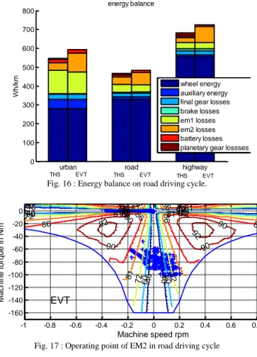
To explain the higher fuel consumption of EVT topology compared to THS, an energetic study has been performed [19]. Considering a charge-sustaining operating mode, the total amount of energy is provided by the engine. The major section of this energy goes to the wheel and propels the vehicle. The rest is used in the vehicle auxiliaries and burned in losses.
Fig. 16 presents the energy balance of the two architectures. As the same driving cycle is followed by both vehicles, the energy going to the wheel is strictly the same. For the same reason the auxiliary and final gear losses are exactly the same. Note that this energy is coming from the global balance including traction and regenerative phases.
This energy balance shows that the main difference appears in the EM2 machine losses. Energy burned in electric EM1 and battery losses are not significantly different. The planetary gear losses in the THS (efficiency =0.97) remains small compared to the difference in EM2 losses.
To explain the higher losses in EM2 in the EVT cases, the operating point of the machine has been represented in road condition driving cycle (Fig. 17). This figure is the efficiency maps of the EM2 machine plus INV2 inverter. Efficiency is represented by coloured lines in torque versus speed area. Operating points of the machine appear in blue.
EVT EM2 machine operates at relatively high torques and the speed of EM2 remains low due to the differences between engine speed and drive-shaft speed. Thus, even if the optimal control chooses the best system efficiency operation, the machine operates mainly in an area with low efficiency.
Moreover, the ICE operates in a worse area with EVT than with THS [19]. The mean specific consumption in road condition is 225 g/kW.h with THS compared to 229 in the case of the EVT architecture.
To improve the EVT system and reduce EM2 losses many solutions can be proposed. The EM2 design may be changed trying to improve the efficiency of the operating area. This could be performed using an iterative design process aiming to optimize the systems efficiency. Nevertheless the electrical machines keep a low efficiency at low speed. The EM2 can be scaled and oversized but it is not desirable for cost and size consideration and will be difficult in the case of a double rotor integrated machine [11]. The final gear ratio can be changed but this will also change the EM1 operating points and the global dynamic performances of the vehicle. For these reasons we consider in this paper the insertion of a gear between the engine and the EM2 electrical machine (section IV.B) that shifts the operating points of EM2 to a better efficiency region.
8
urban road highway
0 100 200 300 400 500 600 700 800 W h /km energy balance wheel energy auxiliary energy final gear losses brake losses em1 losses em2 losses battery losses planetary gear lossses
THS EVT THS EVT THS EVT Fig. 16 : Energy balance on road driving cycle.
-1 -0.8 -0.6 -0.4 -0.2 0 0.2 0.4 0.6 0.8 1 x 10⁴ -160 -140 -120 -100 -80 -60 -40 -20 0 Machine speed rpm Ma ch ine to rqu e i n N m 46 46 46 46 46 60 60 60 6072 6072 72 7281 72 81 81 86 86 86 90 90 90 92 92 46 46 46 46 46 60 60 60 60 60 72 72 72 72 72 81 81 81 81 86 86 86 90 90 90 92 EVT
Fig. 17 : Operating point of EM2 in road driving cycle
B. Result for the new EVT-based solution
Considering that in the case of EVT, the EM2 operates in a low efficiency area, a gear (named ICE-G) can be inserted between engine and EM2 to increase the EM2 speed (Fig. 18). Note that, using a planetary gear with fixed ring, the volume of this gear can be equivalent to the THS’ one. No supplementary space is thus required.
A parametric study has been performed to find the best gear ratio.
It is supposed that the gear efficiency equals 0.97 which is the same value as the planetary gear efficiency of THS.
Fig. 19 shows the optimal fuel consumption obtained with backward model and dynamic programming vs. gear ratio. It is presented for different driving cycles. The diamond-shaped points represent the THS fuel consumption. Looking at different driving cycles a good trade-off seems to select a gear ratio of 1/2.75. For such ratio the fuel consumption of both architectures may be quite the same (TABLE 7).
TABLE 7 :FUEL CONSUMPTION ON DIFFERENT DRIVING CYCLE THS AND EVT WITH GEAR
drive cycle THS fuel consumption (l/100 km)
EVT fuel consumption (l/100 km) NEDC 3.73 3.73 urban 4.54 4.73 road 3.86 3.82 highway 5.59 5.63 ICE EM1 INV2 Battery FG INV1 ICE-G EM2
Fig. 18 : EVT architecture with gear between Engine and EM2
0.2 0.3 0.4 0.5 0.6 0.7 0.8 0.9 1 3.5 4 4.5 5 5.5 6 gear ratio fu e l co n su m p ti o n i n l /1 0 0 km NEDC urban road highway
Fig. 19 : Fuel consumption of EVT versus gear ratio on different driving cycles
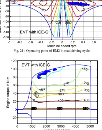
As in the previous section, an energetic comparison is performed between THS and EVT with ICE gear. Fig. 20 is the comparative energy balance in real use condition for the two architectures. It clearly appears that using an additional gear the EM2 losses are drastically reduced compared to the original architecture (Fig. 16). This can be explained looking at the operating points of the ICE and EM2 which have been really shifted to join efficiency areas close to those of THS (Fig. 21 and Fig. 22) when adding a gear. The mean specific consumption in the road driving conditions becomes 222 g/kW.h with EVT against 225 g/kW.h with THS. It is noted that in urban conditions the consumption remains 5% higher. This is mainly due to EM1 losses which increase as the management chooses the best compromise between EM2 and EM1 efficiency.
urban road highway
0 100 200 300 400 500 600 700 W h /km energy balance wheel energy auxiliary energy final gear losses brake losses em1 losses em2 losses battery losses planetary gear or engine gear lossses
THS EVT THS EVT THS EVT
9 -1 -0.8 -0.6 -0.4 -0.2 0 0.2 0.4 0.6 0.8 1 x 10⁴ -160 -140 -120 -100 -80 -60 -40 -20 0 Machine speed rpm Ma ch ine to rqu e i n N m 46 46 46 46 46 60 60 60 6072 6072 72 7281 72 81 81 86 86 86 90 90 90 92 92 46 46 4646 6046 60 60 60 60 72 72 72 72 72 81 8181 81 86 86 86 90 90 90 92
EVT with ICE-G
Fig. 21 : Operating point of EM2 in road driving cycle
0 1000 2000 3000 4000 5000 -20 0 20 40 60 80 100 120 Engine speed rpm En gin e t orq ue in N.m 100 100 100 120 120 120 150 150 150 160 160 160 170 170 170 180 180 180 190 190 190 200 200 200 205 205 205 210 210 210 215 215 215 225 225 225 225 250 250 250 250 250 250 275 275 275 275 275 275 300 300 300 300 300 300 400 400 400 400 400 400
EVT with ICE-G
Fig. 22 : Operating point of Engine in road driving cycle
VI. CONCLUSION
The off-line optimal control based on dynamic programming has been developed and applied to two SP-HEVs topologies. It has been applied to the well known Prius-II and to a virtual EVT based HEV built with the same components. A comparative study on different driving cycles shows that the EVT fuel consumption is approximately 10 % higher than that of the Prius-II.
The benefit of including a gear between the engine and the EVT has then been proven. Choosing a gear ratio around 1/2.75 reduces the EVT fuel consumption which reaches the level of the Prius-II consumption.
Concerning weight and volume of the two systems, the first results show values of the same order. Nevertheless, there are many EVT improvement possibilities: burying the magnet, adopting a V magnet structure, improving the slot shape, reducing the rotor thickness... The EVT may then be a good alternative to the THS systems. However, the use of a rotating armature fed by power electronics should be carefully studied.
To compare more precisely the performances of both topologies, a more global sizing approach is necessary, and the comparison has to be made with an optimized EVT. Continuing this work, this approach is currently in progress.
REFERENCES
[1] CC. Chan, “The state of the art of electric and hybrid vehicles”, Proceedings of the IEEE, vol. 90, (Feb.2002), issue2, pp 247-275. [2] JM. Miller, “Propulsion systems for hybrid vehicles”, The Institution of
Engineering and Technology (December 2003), ISBN: 0863413366. [3] M.Ehsani, Yimin Gao, J.M.Miller, “Hybrid Electric Vehicles:
Architecture and Motor Drives”, Proceedings of the IEEE, Vol. 95, N°4, April 2007, pp 719-728
[4] E. Vinot, R.Trigui, B.Jeanneret, J. Scordia, F. Badin, “HEVs Comparison and Components Sizing Using Dynamic Programming”, IEEE VPPC’ 07, Arlington, Texas.
[5] Toyota Hybrid System THS II, Special Reports_12 Toyota Motor Corporation, Publics affairs Division, available at www.toyota.co.jp/en/tech/environment/ths2/SpecialReports_12.pdf. [6] K. Muta, M. Yamazaki, J. Tokiada, “Development of New Generation
Hybrid System THS II - Drastic Improvement of Power Performance and Fuel Economy”, SAE Technical Paper 2004-01-0064
[7] J.M. Miller, « Hybrid electric vehicle propulsion system architectures of the e-CVT type », IEEE Transaction on Power Electronics., vol.21, no. 3, pp 756-767, May 2006.
[8] B. Mashadi and S.A Emadi, « Dual-mode power-split transmission for hybrid electric vehicles », IEEE Transactions on Vehicular Technology, vol.59, no. 7, pp 3223-3232, Sep 2010.
[9] M. J. Hoeijmakers, J. A. Ferreira. “The electric variable transmission”. IEEE Transactions on Industry Applications, vol. 42, n.4, pp. 1092-1093, July/August 2006
[10] P. Zheng, R. Liu, Q. Wu, J. Zhao, Z. Yao. “Magnetic coupling analysis of four-quadrant transducer used for hybrid electric vehicles”. IEEE Transactions on Magnetics,Vol.43, No. 6, 2007, pp. 2597-2599 [11] Y. Cheng, R. Trigui, C. Espanet, A. Bouscayrol and S. Cui,
“Specifications and Design of a PM Electric Variable Transmission for Toyota Prius II”, IEEE Transactions on Vehicular Technology, Vol. 60, No.9, Nov. 2011.
[12] Y. Cheng, C. Espanet, R. Trigui, A. Bouscayrol and S. Cui, “Design of a Permanent Magnet Electric Variable Transmission for HEV Application”, IEEE VPPC 2010, 1-3 Sept 2010, Lille-France.
[13] Cui Shu-mei, Huang Wen-xiang, Zhang Qian-fan, “Research on power density improvement design of an HEV using induction machine based electrical variable transmission”, IEEE VPPC 2008, 3-5 Sept 2008, Harbin-China.
[14] Guo Xizheng, Wen Xuhui, Zhao Feng, Fan Tao, “Comparison of two different structure of permanent magnet dual mechanical port machine”, IEEE VPPC 2008, 3-5 Sept 2008, Harbin-China.
[15] E. Vinot, J.Scordia, R.Trigui, B.Jeanneret, F.Badin “Model simulation, validation and case study of the 2004 THS of Toyota Prius”, Int. Journal of Vehicle Systems Modelling and Testing, Vol.3, No.3, 2008, pp 130-167.
[16] A. Kimura, T. Abe, S. Sasaki,” Drive force control of a parallel-series hybrid system”, JSAE Review 20 (1999), pp 337-341.
[17] Y. Cheng, K. Chen, C.C. Chan, A. Bouscayrol, S. Cui, “Global modelling and control strategy simulation for a Hybrid Electric Vehicle using Electrical Variable Transmission”, IEEE Vehicular Technology Magazine, vol. 4, no. 2, June 2009, pp. 73-79.
[18] Min-Joong Kim and Huei Peng, ”Power Management and Design Optimization of Fuel Cell/Batterry Hybrid Vehicle”, Journal of power sources, Vol. 165, issue 2,March 2007, pp.819-832.
[19] E.Vinot, R. Trigui, Y. Cheng, A. Bouscayrol, C. Espanet, “Optimal Management and Comparison of SP-HEV vehicles using the dynamic programming method”, IEEE VPPC 2012, 10-12 Oct 2012, Seoul-Corea.
[20] J.Scordia, M.Desbois-Renaudin, R.Trigui, B.Jeanneret and F.Badin.“Global Optimisation of Energy Management Laws in Hybrid Vehicles Using Dynamic Programming”. I.J.Vehicle Design, Vol.39, No.4, 2005, pp 349-367.
[21]M. Koot, J.Kessel, B. de Jager, W.Heemels, P. van den Bosch, M. Steinbuch, “Energy Management Strategies for Vehicular Electric Power Systems”, IEEE Transactions on Vehicular Technology, Vol.54, N°3, may 2005, pp 771-782.
10
[22]D.E. KirK, “Optimal Control Theory, An Introduction”, Dover Publications, Inc. ISBN : 0486434842.
[23]Jinming Liu and Huei Peng,”Modeling and control of a power-Split Hybrid Vehicle”, IEEE Transactions on Control Systems Technology, Vol. 16, No.6, Nov. 2008.
[24]M. Olszewski, ”Evaluation of 2004 Toyota Prius Hybrid Electric Drive”,ORNL/TM-2006/423
[25]J.S. Hsu, C.W. Ayers, C.L. Coomers, “Report on Toyota/prius motor design and manufacturing assessment”,ORNL/TM-2004/137
[26]C. Desai, S.S. Williamson, “Optimal Design of a Parallel Hybrid Electric Vehicle using Multi-Objective Genetic Algorithms”, IEEE-VPPC, 2009, pp. 871-876.
[27]S. Buerger; B. Lohmann; M. Merz; B. Vogel-Heuser; M. Hallmannsegger. “Multi-objective optimization of hybrid electric vehicles considering fuel consumption and dynamic performance”, IEEE-VPPC, 2010, 1-3 Sept 2010, Lille-France.
[28]C. Bertram; D. Buecherl; A. Thanheiser; H.-G. Herzog. “Multi-objective optimization of a parallel hybrid electric drive train” IEEE-VPPC, 2011, 6-9 Sept 2011, Chicago-USA.
[29]V.Reinbold, E. Vinot, L.Gerbaud “Global Optimization of a parallel hybrid vehicle using optimal energy management”, OIPE 2012 Workshop, 19-21 Sept, Ghent, Belgium.
[30]M.André, “The ARTEMIS European driving cycles for measuring car pollutant emissions”, Science of The Total Environment, Volumes 334-335, December 2004, pp 73-84.
Emmanuel Vinot received the
engineering degree of Ecole National Supérieure d’Electricité de Grenoble (1997), the M.S. degree in electrical engineering from the Laval University, Québec, Canada (1998) and the Ph. D degree from the Electrotechnic Laboratory of the national Polytechnique Institute of Grenoble (INPG), France, in 2000.
Since 2005 he is working in the French Institute of science and technology for Transport, development and network (IFSTTAR) in the hybrid vehicle team. His main interests are systemic model of vehicle and components, system management optimisation, and system and electrical machine design.
Rochdi Trigui (M’06) was born in Sfax,
Tunisia, in 1969. He received the electrical engineering degree from the National High School of Electrical and Mechanical Engineering, Nancy, France, in 1993 and the Ph.D. degree in electrical engineering from the National Polytechnic Institute of Lorraine, Nancy, in 1997.
Since 1998, he has been a Researcher in the field of electric and hybrid vehicles with the French National Institute for Transport and Safety Research (INRETS), Bron, France. Since 2008, he has been the head of the Hybrid Electric Vehicle team with INRETS, now called the French Institute of Science and Technology for Transport, Development and Networks (IFSTTAR). He is an Associate Editor of the Journal of Asian Electric Vehicle.
Dr. Trigui is currently a member o the IEEE Vehicular Technology Society. He was the Cochair of the IEEE Vehicle Power and Propulsion Conference in 2010.
Alain Bouscayrol (M’02) received the
Ph.D. degree in electrical engineering from INP Toulouse, France, in 1995.
He had been engaged as Associate Professor at the L2EP of the University of Lille1 (France) in 1996, and became Professor in 2005.
His research interests include graphical descriptions for electrical machine controls, tractions application and hybrid vehicles. From 1998 to 2004, he managed the “Multimachine Muticonverter Systems” project of national research Group (GdR) SDSE-ME2MS of CNRS (French National Scientific Research Centre). Since 2005, he has managed MEGEVH, a French national network on hybrid vehicles.
Christophe Espanet (M’04) is received
the Ph.D. degree from the University of Franche-Comte (France) in 1999. His doctoral research dealt with the design and the optimization of PM in-wheel motors.
From 1999 to 2007, he has been an Associate Professor at the University of Franche-Comte in the Laboratory of Electrical Engineering and Systems (L2ES). He is now full professor at the University of Franche-Comte (France) and Head of the Team “Non Conventional Electric and Thermal Machines” in the FEMTO-ST Institute. He is also deputy director in charge of research at the UDR-STGi. His research interests include the modeling and the design of electrical systems and in particular electric machines.
Yuan Cheng received the B.S., M.Sc.,
and Ph.D. degrees all in Electrical Engineering from Harbin Institute of Technology (HIT), Harbin, China, in 2002, 2004 and 2009 respectively.
His research interests include design and control of electric machines, modeling and control of electric (EVs) and hybrid electric vehicles (HEVs). From 2009 to 2011, he carried out the research of Permanent-Magnet EVT and its applications in HEVs in the frame of MEGEVH network, France.
In 2012, he joined PSA Peugeot Citroën in Paris, where he is responsible for the research of novel energetic conversion systems for automotive applications and the development of powertrain simulation tools.
Vincent Reinbold received the
engineering degree of Ecole National Supérieure d’Electricité de Grenoble (2011). He is currently a Ph.D student.
His research interests include the optimal design of electrical machine for hybrid vehicle.