ECOLE DE TECHNOLOGIE SUPÉRIEURE UNIVERSITÉ DU QUÉBEC
THESIS PRESENTED TO
ÉCOLE DE TECHNOLOGIE SUPÉRIEURE
IN PARTIAL FULFILLEMENT OF THE REQUIREMENTS FOR THE DEGREE OF DOCTOR OF PHILOSOPHY
Ph. D.
BY
Pradeep Kumar THALLA
BIOACTIVE COATING WITH LOW-FOULING POLYMERS FOR THE DEVELOPMENT OF BIOCOMPATIBLE VASCULAR IMPLANTS
MONTREAL, NOVEMBER 14, 2014
This Creative Commons licence allows readers to download this work and share it with others as long as the author is credited. The content of this work may not be modified in any way or used commercially.
BOARD OF EXAMINERS (THESIS PH.D.) THIS THESIS HAS BEEN EVALUATED BY THE FOLLOWING BOARD OF EXAMINERS
Prof. Sophie Lerouge, Thesis Supervisor
Department of Mechanical Engineering at École de technologie supérieure
Prof. Gregory De Crescenzo, Thesis Co-supervisor
Department of Chemical Engineering at École Polytechnique de Montreal
Prof. Nicola Hagemeister, Chair, Board of Examiners
Department of Automated Production at École de technologie supérieure
Prof. Robert Hausler, Member of the jury
Department of Construction Engineering at École de technologie supérieure
Prof. Maud Gorbet, External Evaluator
Department of Systems Design Engineering at University of Waterloo
THIS THESIS WAS PRESENTED AND DEFENDED
IN THE PRESENCE OF A BOARD OF EXAMINERS AND THE PUBLIC ON OCTOBER 8, 2014
ACKNOWLEDGEMENTS
First and foremost, I would like to express my profound thanks and appreciation to my supervisors. I am extremely grateful to Dr. Sophie Lerouge for always being there with valuable guidance and encouragement. Her support, helpful advice and patience played a key role enabling me to reach this point. I would like to express my gratitude to my co-supervisor, Dr. Gregory De Crescenzo for his constant support throughout my journey in completing this work. Having two highly accomplished researchers in the field of biomaterials as my supervisors enabled me to learn a lot about not only the field but also how to tackle research problems in general.
Since this is a multidisciplinary project, I had the support and cooperation of other research labs. Therefore, I would like to extend my sincere gratitude to Dr. Yahye Merhi for his expertise in thrombosis experiments, valuable suggestions on my research and support for completing this work. I would also like to thank Professor Michael R. Wertheimer for his expertise in plasma polymerization and support during this project. I would like to continue by acknowledging the researchers of Sophie Lerouge’s and Gregory De Crescenzo’s labs. Many thanks to Marion Marie for valuable assistance in the lab, particularly for cell culture experiments. I would like to thank my co-authors who contributed to papers and provided support by preparing samples; Benoit for his guidance on chemical grafting, Hicham for his help with perfusion assays, Angel, Bachir and Houman for LP depositions and Pauline for cell culture experiments. Finally, I would also like to thank all of my colleagues (Elias, Audrey, Caroline, Fatemeh and Matthew) at our research lab, Laboratoire de biomatériaux endovasculaires (LBeV), for their encouragement, scientific discussions and help with translation (French to English) when I had difficulties understanding French.
I am deeply grateful to jury members Professor Nicola Hagemeister, Professor Maud Gorbet, and Professor Robert Hausler for taking the time to review my doctoral thesis.
Last but not least, I would like to thank my family, whose support was contributed so much to the completion of this project. My wife, Tarangini Reddy, has been an infinite source of inspiration, encouragement and understanding during my time as a PhD student, and this has made me realize that together anything is possible. My mother Vijaya Thalla, my sister Sindhura and my in-laws Rohini Kumar, Vijaya Laxmi, Uday Bhaskar, and Vasanth Reddy have continually supported me, stood behind me over the years and fostered my desire to take on new challenges. I would also like to mention the names of my well-wishers Jyothi, Raju, Shruthi and Venu, for their constant encouragement and support during my time as a PhD student.
Finally, I would like to dedicate this thesis to my late father Venkat Reddy Thalla and my spiritual guru Shri Parthasaradhi Rajagopala Chariji.
REVÊTEMENT BIOACTIF AVEC POLYMÉRES DE LOW-FOULING POUR LE DÉVELOPMNET DES IMPLANTS VASCULAIRES BIOCOMPATIBLES
Pradeep Kumar THALLA RÉSUMÉ
Le remplacement de vaisseaux sanguins occlus et la réparation endovasculaire des anévrismes de l’aorte abdominale (EVAR) effectués respectivement à l’aide de prothèses vasculaires synthétiques et d’endoprothèses couvertes, mènent tous deux à de fréquentes complications cliniques due à une problématique similaire : les matériaux utilisés (généralement le polyéthylène téréphthalate (PET) et le polytétrafluoroéthylène expansé (ePTFE) n’ont pas les propriétés de surface permettant de réduire les réactions biologiques indésirables tout en favorisant les interactions cellulaires requises pour la croissance des tissus biologiques. Par conséquent, l'objectif principal de cette thèse consistait à créer un revêtement bioactif sur les biomatériaux vasculaires pour réduire la thrombose tout en favorisant la croissance cellulaire.
Le premier objectif a consisté à mettre au point une surface empêchant l’adsorption des protéines (communément appelée « low-fouling ») à l’aide de polyéthylène glycol (PEG) à bras multiples. Un revêtement polymérisé par plasma riche en amine primaire (LP) a été utilisé comme substrat afin d’obtenir un revêtement polyvalent, pouvant être recréé sur n’importe quel type de biomatériaux ou de surface, ce qui n’est pas le cas des méthodes actuelles qui requièrent d’optimiser la technique de greffage pour chaque nouveau biomatériau. Tel que démontré par microbalance à cristal de quartz avec dissipation (QCM-D), par mesure directe de fluorescence ainsi que lors d’essais de perfusion sanguins , les revêtements de PEG créés génèrent une très faible adsorption de protéine et presque pas l'adhésion des plaquettes après 15 min de perfusion dans le sang total. Bien que l’adsorption des protéines ne soit pas empêchée à 100% et que les propriétés anti-plaquetaires ne permettent pas de conclure sur l’absence de thrombogénicité à long terme in vivo du revêtement, les propriétés de ce dernier peuvent être exploitées pour y coupler des molécules bioactives. Par conséquent, le second objectif consistait à développer un revêtement bioactif innovant et polyvalent en utilisant la combinaison de peptide d’adhésion (KQAGDV/RGD) et de facteur de croissance épidermique (EGF) greffé par le biais de coils électrostatiques. Le dextran carboxyméthylé (CMD) a été choisi comme une alternative possible au PEG en raison de ses meilleures propriétés « low-fouling » et la présence de groupes terminaux carboxyl abondants. Bien que la technique QCM-D nous ait permis d'optimiser la combinaison de l'immobilisation KQAGDV / RGD et EGF, les essais cellulaire n'ont pas montré d'amélioration de l'adhésion des cellules musculaires lisses vasculaires (CMLV) sur les surfaces PEG ou CMD modifiées par les peptides.
Ce résultat met en évidence, parmi d’autres facteurs, le difficile compromis à trouver pour empêcher l’adsorption des protéines sans empêcher l’adhésion cellulaire. Des travaux
antérieurs du laboratoire suggéraient que la chondroitine sulfate (CS), un glycoaminoglycan sulphaté, permettait de trouver ce compromis. Pour cette raison, le dernier objectif de cette thèse a consisté à étudier les propriétés de revêtements de CS comparativement aux deux polymères « low-fouling », le PEG et le CMD. Il a été démontré que la CS présente des propriétés anti-fouling sélectives puisque l’adsorption du fibrinogène est presque totalement supprimée tandis que d’autres protéines (et notamment certains facteurs de croissance connus pour interagir avec la CS) sont favorisées. La CS, comme le PEG et le CMD, diminue nettement l’adhésion plaquetaire en deça du niveau observé sur le PET. Par contre, alors que l’adhésion cellulaire sur le PEG et le CMD est très limitée, la CS favorise un attachement cellulaire prononcé, avec adhésion focale et résistance au cisaillement. Au contraire, les cellules endothéliales se détachent facilement du PET non modifié. Ainsi, les revêtements de CS forment une surface peu thrombogène favorisant la croissance d’une couche endothéliale complète et stable qui pourra agir comme surface anti-thrombotique active. Ensemble, l’utilisation du polymère plasma et de la CS greffée, suivie éventuellement d’immobilisation de facteurs de croissance, semble avoir un fort potentiel comme revêtement bioactif pour optimiser la biocompatibilité et les résultats cliniques des implants, en particulier des prothèses vasculaires.
Mots-clés: revêtement bioactif, prothèse vasculaire, endoprothèse, low-fouling, non thrombogénique, adhésion de peptides, facteur de croissance épidermique, microbalance à cristal de quartz avec dissipation.
BIOACTIVE COATING WITH LOW-FOULING POLYMERS FOR THE DEVELOPMENT OF BIOCOMPATIBLE VASCULAR IMPLANTS
Pradeep Kumar THALLA ABSTRACT
The replacement of occluded blood vessels and endovascular aneurysm repair (EVAR) are performed with the use of synthetic vascular grafts and stent grafts, respectively. Both implants lead to frequent clinical complications that are different but due to a similar problem, namely the inadequate surface properties of the polymeric biomaterials used (generally polyethylene terephthalate (PET) or expanded polytetrafluoroethylene (ePTFE)). Therefore the general objective of this thesis was to create a versatile bioactive coating on vascular biomaterials that reduce material-induced thrombosis and promote desired cell interactions favorable to tissue healing around implants. The use of low-fouling backgrounds was decided in order to reduce platelet adhesion as well as the non-specific protein adsorption and thus increase the bioactivity of immobilized biomolecules.
As part of the preliminary objective, a multi-arm polyethylene glycol (PEG) was chosen to create a versatile low-fouling surface, since the current coating methods are far from being versatile and rely on the availability of compatible functional groups on both PEG and the host surface. This PEG coating method was developed by taking advantage of novel primary amine-rich plasma polymerized coatings (LP). As demonstrated by quartz crystal microbalance with dissipation (QCM-D), fluorescence measurements and platelet adhesion assays, our PEG coatings exhibited low protein adsorption and almost no platelet adhesion after 15 min perfusion in whole blood. Although protein adsorption was not completely abrogated and short-term platelet adhesion assay was clearly insufficient to draw conclusions for long-term prevention of thrombosis in vivo, the low-fouling properties of this PEG coating were sufficient to be exploited for further coupling of bioactive molecules to create bioactive coatings. Therefore, as a part of the second objective, an innovative and versatile bioactive coating was developed on PEG and carboxymethylated dextran (CMD), using the combination of an adhesive peptide (KQAGDV/RGD) and epidermal growth factor (EGF). CMD was chosen as an alternative to PEG due to its better low-fouling properties and the presence of abundant carboxyl terminal groups. Although the QCM-D technique enabled us to optimize the combined immobilization of KQAGDV/RGD and EGF, cell adhesion assay results did not show improvement of vascular smooth muscle cell (VSMC) adhesion on peptide-modified PEG or CMD surfaces.
Among the reasons explaining low cell adhesion on peptides grafted low-fouling surfaces is the difficulty of preventing protein adsorption/platelet adhesion without significantly reducing cell adhesion. Preliminary data in our laboratory indicated that CS could be an ideal substrate to find this compromise. For that reason, the final objective of this PhD consisted in evaluating the potential of chondroitin sulfate (CS) coating by comparing its properties with well-known low-fouling polymers such as PEG and CMD. It was shown
that CS presents selective low-fouling properties, low-platelet adhesion and pro-endothelial cell (EC) adhesive properties As demonstrated by QCM-D and fluorescence measurements, CS was as effective as PEG in reducing fibrinogen adsorption, but it reduced adsorption of bovine serum albumin (BSA) and fetal bovine serum (FBS) to a lower extent than PEG and CMD surfaces. Whole blood perfusion assays indicated that all three surfaces drastically decreased platelet adhesion and activation to levels significantly lower than PET surfaces. However, while EC adhesion and growth were found to be very limited on PEG and CMD, cell attachment on CS was strong, with focal adhesion points and resistance to shear stress. CS coatings therefore form a low-thrombogenic background promoting the formation of a confluent endothelium layer, which may then act as an active anti-thrombogenic surface. CS coating can also be used to further graft biomolecules. Combination of LP, CS coating followed by GF immobilization shows great promise as a bioactive coating to optimize the biocompatibility and clinical outcome of vascular implants, in particular vascular grafts.
Key words: bioactive coating, vascular graft, stent-graft, low-fouling, non-thrombogenic, adhesion peptide, epidermal growth factor, QCM-D.
TABLE OF CONTENTS
Page
INTRODUCTION ...1
CHAPTER 1 LITERATURE REVIEW ...5
1.1 Clinical problematic ...5
1.1.1 Morphology of arteries ... 5
1.1.2 Vascular injury ... 6
1.1.3 Vascular prostheses and their limitations ... 8
1.2 Blood-material interactions ...12
1.2.1 Protein-surface interactions and their influence on protein adsorption .... 13
1.2.2 Thrombus formation ... 18
1.2.3 Blood coagulation ... 19
1.2.4 Regulation of thrombosis by endothelium ... 21
1.3 Surface modification for blood compatibility ...23
1.3.1 Low-fouling coatings ... 23
1.3.2 Surface modification with anticoagulants ... 33
1.4 Modifying surface physico-chemical properties to promote cell adhesion ...37
1.5 Bioactive coatings to promote cell adhesion and growth ...39
1.5.1 Coatings made of ECM proteins ... 39
1.5.2 Surface modification with peptides ... 44
1.5.3 Surface modification with growth factors ... 54
1.5.4 Combination of peptide and growth factor ... 64
1.6 QCMD- technique ...68
1.6.1 Introduction ... 68
1.6.2 Fundamental principles of the QCM-D technique ... 68
CHAPTER 2 OBJECTIVES AND HYPOTHESIS ...75
CHAPTER 3 MATERIALS AND METHODS ...79
3.1 Surface preparation and coating methods ...79
3.1.1 Cleaning samples ... 79
3.1.2 Plasma polymerization ... 80
3.1.3 Chemical grafting of PEG, CMD and CS ... 81
3.1.4 Covalent immobilization of peptides and epidermal growth factor (EGF) ... 85
3.2 Surface characterization ...87
3.2.1 X-ray photoelectron spectroscopy (XPS) ... 87
3.2.2 Static Water Contact Angle ... 88
3.3 QCM-D measurements ...89
3.3.1 QCM-D system ... 89
3.3.2 QCM-D measurements ... 92
3.3.4 Measuring cell adhesion ... 96
3.4 Protein adsorption studies by fluorescence measurements ...96
3.4.1 Protein adsorption studies on PEG, CMD and CS surfaces ... 97
3.4.2 Micro -patterning ... 97
3.5 Platelet adhesion assays ...98
3.5.1 Perfusion system ... 99
3.5.2 Platelet adhesion assay with radio-labeled platelets ... 100
3.5.3 Platelet adhesion assay using fluorescence staining ... 101
3.5.4 Scanning electron microscopy ... 102
3.6 Cell culture experiments ...103
3.6.1 HUVEC adhesion and growth ... 103
3.6.2 VSMC adhesion assay on peptide grafted surfaces ... 105
3.7 Statistical Analysis ...105
CHAPTER 4 RESULTS AND DISCUSSION ...107
4.1 Develop a low-fouling and low-thrombogenic coating that can be applicable to a wide variety of biomaterial surfaces. ...107
4.1.1 Rationale ... 107
4.1.2 Results ... 108
4.1.3 Discussion ... 118
4.2 Develop a bioactive coating with the combination of peptide and GF on low- fouling background. ...121
4.2.1 Rationale ... 121
4.2.2 Results ... 122
4.2.3 Discussion ... 132
4.3 Evaluate the advantages and limitations of using CS coating for vascular grafts ....139
4.3.1 Rationale ... 139
4.3.2 Results ... 140
4.3.3 Discussion ... 150
CHAPTER 5 GENERAL DISCUSSION ...155
CONCLUSION ...167
LIST OF TABLES
Page Table 1.1. Major constituents of human blood serum and their biological
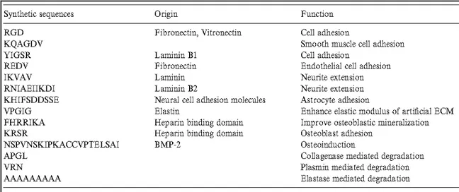
functions. Taken from (David Richard Schmidt, 2009). ...18 Table 1.2. Selective synthetic peptide sequences of extracellular matrix proteins
and their functions. Taken from (Shin, Jo et Mikos, 2003). ...46 Table 4.1. Surface elemental concentration (in At. %) of C, O, Si and N, as
determined by XPS on amino-coated glass and PEG-modified
surfaces using various star PEG coupling concentrations. ...111 Table 4.2. Summarized observations of various experiments (at least 4 samples
tested for each condition) performed to investigate the influence of
immobilized peptides on VSMC adhesion ...131 Table 4.3. Mean percentage reduction of protein-adsorbed mass compared
LIST OF FIGURES
Page Figure 1.1. Schematic view of the organization of the three layers (intima, media
and adventitia) of an artery. Taken from (Muscle anatomy of the
body, 2014). ...6 Figure 1.2. Schematic view of narrowing artery due to atherosclerotic plaque.
Taken from (Merck, 2014). ...7 Figure 1.3. Schematic of (A) commercially available ePTFE vascular grafts
(GORE-TEX) for coronary artery bypass and (B) stent graft
placement for the repair of EVAR (Biotextiles, 2014). ...9 Figure 1.4. Schematic shows a simplified view of the interaction of blood elem
ents with biomaterial surface. Taken from (Courtney et Forbes, 1994). ...13 Figure 1.5. Schematic view of protein conformational changes upon adsorption
on the material surfaces. Taken from (David Richard Schmidt, 2009). ...15 Figure 1.6. A schematic view of protein-surface interactions. Both the surface
and the protein have a number of interacting domains with charged, hydrophobic and polar character. I mage taken from
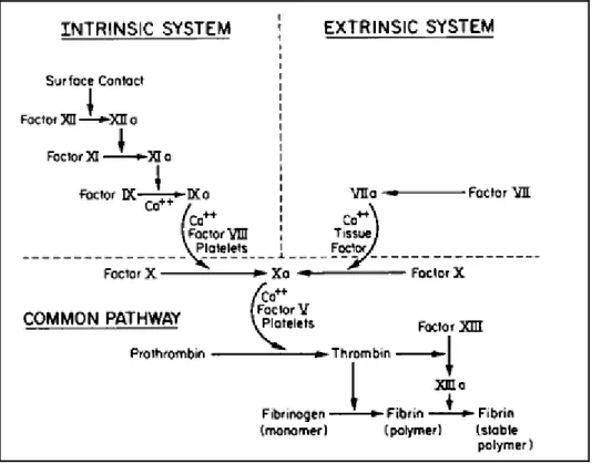
(Andrade et Hlady, 1986). ...16 Figure 1.7. Schematic diagram of a simplified view of the blood coagulation
cascade that includes intrinsic and extrinsic pathways.
Taken from (Gorbet et Sefton, 2004). ...21 Figure 1.8. (a) EC regulation of coagulation and (b) platelet adhesion and
activation. Taken from (Li et Henry, 2011b). ...23 Figure 1.9. Schematic shows hydrogen bonding between ether oxygen atoms.
Image adapted and modified from (Andrade et Hlady, 1986). ...25 Figure 1.10. Schematic view of (a) protein repulsion on hydrated polymer chains
and (b) prevention of protein adsorption on PEG layer by excluded volume-steric repulsion. Image adapted from
(Andrade et Hlady, 1986). ...26 Figure 1.11. Schematic shows three different PEG regimes, depending on the
PEG chain density. The PEG conformation on the surface changes from non-overlapping "mushrooms" to fully extended "brushes" at different grafting densities. Image adapted and slightly modified
Figure 1.12. Schematic diagram of a) a linear PEG molecule and b) an end-functionalized 4-arm star PEG. The circles represent end functional groups by which the molecules may tether to surfaces. Image
adapted from (Irvine et al., 1998). ...29 Figure 1.13. Schematic view of the possible interactions and orientations of
biomolecules when they are immobilized on (a) an amine-
functionalized surface vs. (b) a 4-arm star PEG modified surface ...31 Figure 1.14. Schematic shows (a) the chemical structure of dextran and (b)
the configuration of surface-bound dextran polymer. Image
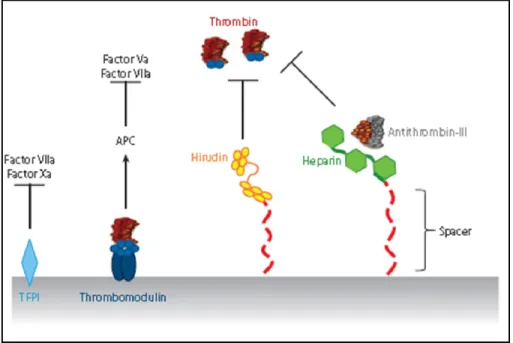
adapted from (Massia, Stark et Letbetter, 2000). ...33 Figure 1.15. Schematic view of mechanism of action of immobilized heparin,
hirudin, thrombomodulin (TM) and tissue factor pathway inhibitor
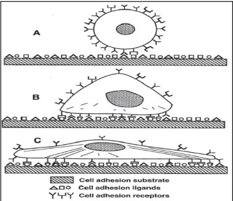
(TFPI) to inhibit coagulation. Taken from (Li et Henry, 2011b)...36 Figure 1.16. Schematic view of progression of anchorage dependent cell adhesion.
(A) Initial contact of cell with solid substrate that has multiple binding domains. (B) Formation of bonds between cell surface receptors and ligands. (C) Cytoskeletal reorganization for
increased adhesion strength. Taken from (Massia, 1999). ...41 Figure 1.17. The chemical structure and nomenclature of RGD peptide.
Image adapted from (Hersel, Dahmen et Kessler, 2003). ...47 Figure 1.18. Coupling of a protected RGD peptide through its N-terminus to a
surface carboxyl group and deprotection of the blocking groups.
Image adapted from (Hersel, Dahmen et Kessler, 2003). ...48 Figure 1.19. Reaction scheme between maleimide group on the surface and
thiol functional group on peptide. Image adapted from
(Hersel, Dahmen et Kessler, 2003; Lateef et al., 2002). ...49 Figure 1.20. Schematic representation of how integrin-mediated activation
regulates the cell/substrate interaction (Owen et al., 2005). ...52 Figure 1.21. Schematic illustration of RGD presentation on star polymers.
(A) The same amount of ligands presented in homogeneous (top) versus ligands presented in discrete clusters (bottom).Image
adapted from (Maheshwari et al., 2000). ...53 Figure 1.22. Cross talk between cells mediated by growth factors and ECM.
Insert illustrates how ECM can control growth factor presentation in a temporal and spatial fashion. Taken from
Figure 1.23. Primary structure of human epidermal growth factor (EGF).
Adapted from (Carpenter et Cohen, 1979). ...57 Figure 1.24. (A) Schematic representation of EGFR domain structure of the
extracellular and intracellular regions. (B) Hetero-dimerization of the EGFR and Erb B2 upon receptor activation. Image adapted
and redrawn from (McInnes et Sykes, 1997). ...58 Figure 1.25. Schematic representing the pathways which lead to the activation of
anti-apoptotic proteins (white) and the inactivation of pro-apoptotic
proteins (black). Taken from (Srokowski et Woodhouse, 2013). ...59 Figure 1.26. Schematic illustration of the interaction between cells and native (a)
and immobilized (b) growth factors (Ito, Kajihara et Imanishi, 1991). ....60 Figure 1.27. Schematic illustration of EGF accessibility to the cellular receptor
when it is tethered to a substrate material via flexible polyethylene
glycol chains. Taken from (Ito, 1998). ...61 Figure 1.28. Helical wheel representation of the heterodimeric parallel E/K
coiled-coil, which shows hydrophobic interaction between V and L residues (at positions a, a', d and d') and electrostatic interchain interactions between E and K residues (at positions e-g' and g-e')
that forms E/K salt bridge. Taken from (Chao et al., 1998). ...63 Figure 1.29. Schematic diagram of an oriented immobilization of EGF onto an
amine-displaying surface through coiled-coil interaction
(Boucher et al., 2009). ...64 Figure 1.30. Schematic diagram of collaborative signaling of growth factor and
integrin receptors. Taken from (Yamada et Even-Ram, 2002). ...65 Figure 1.31. Schematic diagram of FAK function that integrates growth factor
and integrin signals to promote cell migration (Sieg et al., 2000). ...67 Figure 1.32. Schematic illustration of relative changes in the crystal oscillation upon
adsorption of mass (m). Initially, the frequency is constant at its fundamental overtone. When the mass is added to the crystal, the frequency decreases but remains constant. Finally, when the driving power is switched off, the frequency decays and the dissipation can be calculated (image adapted from Q-Sense reported data). ...71 Figure 1.33. Schematic diagram of the geometry of a quartz crystal covered
with a viscoelastic protein film. The film is represented by various parameters such as density (rf), viscosity (hf), elastic shear modulus
by a density (rl), and a viscosity (hl) and for the crystal are
represented by density (rQ), elastic shear modulus (mQ), and
thickness (tQ). Taken from (Höök et al., 2001). ...74
Figure 3.1. Schematic views of the low-pressure, capacitively coupled
radio-frequency plasma reactor. Taken from (Truica-Marasescu et al., 2008). ..81 Figure 3.2. Chemical structure of polyethyleneglycol (PEG), carboxymethyl
dextran (CMD) and chondroitin-4-sulfate (CS). ...83 Figure 3.3. Schematic diagram of star PEG covalent binding reaction. Either
one or two N- hydroxyl succinamide (NHS) terminal groups of star PEG react directly with primary amines through ester-amine reactions to form stable amide bonds; the remaining terminal groups do not participate in coupling, due to steric constraints
(Park, Mao et Park, 1990) and hydrolyze to carboxylic acid
groups during the reaction. ...84 Figure 3.4. Schematic of KQAGDV and K coil peptide grafting using EMCH
linker and E coil EGF tethering through coiled-coil interaction. ...86 Figure 3.5. Schematic diagram of the contact angle and interfacial tensions at
three phase boundaries. ...89 Figure 3.6. Schematic picture of (A) complete setup of the QCM-D equipment
(B) four flow modules chamber and their setup and (C) flow
module with a crystal, dimensions and o-ring position. ...90 Figure 3.7. Schematic shows the viscous penetration depth as function of the
overtone number (Q-Sense reported data). ...91 Figure 3.8. Example of QCM-D data for simultaneous measurements of
frequency (∆f) and (∆D) dissipation changes (for various over tones) during fibrinogen (0.5 mg/mL) adsorption on LP deposited surface. Arrows refer to injection (left) of fibrinogen and rinsing (right)
with PBS solution. ...93 Figure 3.9. Schematic diagram of serial immobilization of KQAGDV peptide,
K coil, Cysteine and E coil EGF, with QCM-D. ...96 Figure 3.10. Image of electron microscopy grids consisting of 184-µm wide
parallel bars separated by 92 µm. ...98 Figure 3.11. Schematic picture of (a) perfusion chamber (b) sample holder and
(c) perfusion system setup along with thermostatically controlled
Figure 3.12. Typical smooth discoid shape of platelets (left) and spherical
shape of activated platelets (right) (Harrison, 2005). ...103 Figure 4.1. Static water contact angles on unmodified amino-coated glass
(left) and LP (right), and after PEG coating at various coupling concentrations (0.55, 1.66, 5, and 15% w/v). Results are expressed as mean ± SD, n=3. *Significantly different from amino-coated glass and LP surfaces (P<0.001), # significantly different from 5% PEG
(P<0.001). ...108 Figure 4.2. XPS high-resolution C1s scans of amino-coated glass (a) before and
(b-e) after star PEG grafting at various coupling concentrations (0.55, 1.66, 5, and 15% w/v). Note that the relative intensity of the C–O peak increased with the PEG coupling concentration; (f) Overlay spectra of 15% PEG-modified on unmodified amino-
coated surface...110 Figure 4.3. QCM-D real-time change in resonance frequency (Δf) and dissipation
(ΔD) related to modified (5% PEG) and unmodified LP surfaces upon exposure to fibrinogen solution (0.5 mg/mL; (1)) followed by
rinsing with PBS (2)...112 Figure 4.4. Time-resolved effect of various PEG coupling concentrations on
fibrinogen (0.5 mg/mL) adsorption. QCM-D data were analyzed according to the Voigt model. Time of fibrinogen injection (1) and rinsing with PBS (2) are indicated. This is an example figure that
shows data from one experiment. ...113 Figure 4.5. Calculated mass of adsorbed fibrinogen (0.5mg/mL) on LP and after
PEG grafting at various coupling concentrations. QCM-D data were analyzed using the Voigt model. Results are expressed as
mean ± SD, n=4 (* result expressed as a mean; n=2 only). ...113 Figure 4.6. Example curves for fibrinogen (0.5 mg/mL) adsorption on LP and on
PEG modified surfaces immersed in PBS over a period of 1 or 28 days. QCMD data were analyzed according to the Voigt model. Time of fibrinogen injection (1) and rinsing with PBS (2) are
indicated. ...114 Figure 4.7. Fluorescence detection of adsorbed Texas red labeled albumin
(0.2 mg/mL) on bare PET, LP alone and LP-PEG coated PET. Results are expressed as mean ± SD (n=4). Background was subtracted from each surface. *Significantly different from PET
Figure 4.8. Fluorescence microscopy images of LP micro-patterns on PET surfaces after exposure to albumin Texas red conjugate. Parallel
pattern surface (a) without PEG grafting and (b) modified with PEG. ...116 Figure 4.9. Platelet adhesion on an intact artery (native artery), injured artery,
PET film, LP and 5% PEG- modified substrates. Results are expressed on a logarithmic scale, as mean ± SD (n=4). * significantly different from PET (P<0.001), # significantly
different from LP + 5% PEG (P<0.001). ...117 Figure 4.10. SEM visualization of platelet adhesion on LP (a, b), PET (c, d) and
LP + 5% PEG (e, f) grafted surfaces. ...118 Figure 4.11. QCM-D frequency shift due to K coil, cysteine and E coil EGF
serial injections on EMCH and PDPH modified CMD surfaces.
Arrows refer to the PBS rinsing. ...123 Figure 4.12. QCM-D frequency shift due to K coil, cysteine and E coil EGF
serial injections on EMCH activated PEG and CMD surfaces. PEG + Cysteine and CMD + cysteine control surfaces corresponds to surface where K coil had not been immobilized. Arrows refer
to the PBS rinsing. ...124 Figure 4.13. QCM-D frequency changes due to immobilization of various
concentrations of KQAGDV and serial immobilization of K coil, Cysteine and E coil EGF on CMD surfaces. Arrows refer to
PBS rinsing. ...125 Figure 4.14. Mass increase corresponding to KQAGDV, K coil grafting and
E coil EGF recruitment on CMD surfaces (previously modified with EMCH linker), as a function of KQADGV concentration that had been initially injected (n≥3). Cys only surface corresponds to negative control surface, on which reactive sites are blocked with
cysteine. ...126 Figure 4.15. The frequency (left panel) and dissipation (right panel) changes
due to VSMC adhesion on LP, PEG and CMD. Arrows refer to the
injection of VSMCs (left) and DMEM rinsing (right). ...127 Figure 4.16. The frequency (left) and dissipation (right) changes due to
VSMC adhesion on LP, CMD and CMD + KQAGDV surfaces. ...129 Figure 4.17. The frequency changes due to RGD (38 µM) grafting (first arrow)
on CMD + EMCH and CMD surfaces (left). VSMC adhesion on
Figure 4.18. VSMC density observed (after 4 h adhesion in serum-free medium) by crystal violet staining on KQAGDV peptide modified and unmodified LP, CMD and EMCH surfaces. Scale bar corresponds
to 200 µm. ...130 Figure 4.19. Static water contact angle measurements of unmodified LP and LP
coated with PEG, CMD and CS (mean ± SD; n ≥ 10);
* p < 0.0001 vs. LP. ...141 Figure 4.20. Static water contact angle measurements of unmodified and modified
amino-coated glass surfaces with PEG, CMD and CS
(mean ± SD; n = 7)...141 Figure 4.21. QCM-D frequency (Δf, panel a) and dissipation (ΔD, panel b)
versus time for fibrinogen (0.5 mg/mL) adsorption on a CMD modified and an LP surface. The arrows refer to the injection of
the protein solution (left) and PBS rinsing (right). ...142 Figure 4.22. The adsorption and desorption kinetics of BSA (a) and 10% (w/v)
FBS (b) on PEG, CMD and CS modified and unmodified LP surfaces. Arrows indicate the start of the protein (left) and
PBS (right) injections. ...143 Figure 4.23. Fluorescence intensity of adsorbed Texas Red labeled albumin
(0.2 mg/mL) on PEG-, 2 CMD- and CS-modified and unmodified LP surfaces, as well as on bare PET control (mean ± 3 SD; n = 8);
* p < 0.0001 vs. PET; # p < 0.0001 vs. CS. ...144 Figure 4.24. Typical images of crystal violet staining after 2 day HUVEC
growth on each surface (scale bar = 200 µm). ...145 Figure 4.25. HUVEC density after 4h (adhesion) and 2 days (growth)
(mean ± SD ; n = 12); * p < 0.0001. ...145 Figure 4.26. Immunostaining of vinculin (red), actin (green), and the nucleus
(blue) after 24 h of HUVEC adhesion on PET, LP, LP-CS and
LP-CMD surfaces. ...146 Figure 4.27. Percentage of surface area covered by platelets after perfusion with
whole blood for 15 min (mean ± SD; n ≥ 5); * p < 0.0001 vs. LP;
# p < 0.0001 vs. PET. ...147 Figure 4.28. Representative images of SEM (a, c, e) and confocal microscopy
(b, d, f, g, h: labeling with CD 61/FITC) for platelet adhesion on LP (a, b), PET (c, d), CS (e, f), PEG (g) and CMD (h) surfaces
Figure 4.29. Cell density on the different surfaces (bare PET and LP +/-CS coating) not perfused (-Perfusion) and after perfusion (+Perfusion) of whole blood (mean ± SD; n = 7); * p < 0.0001 vs. all other surfaces. Confocal microscopy images (right side) of HUVEC growth (7 d; labeled with CellVue Maroon (in blue color)) on PET, before and after 15 min of perfusion. Data adapted from Fadlallah's thesis
(Fadlallah, 2013). ...149 Figure 4.30. (a) Percentage of LP and CS surfaces covered by platelets after
perfusion with whole blood in the absence (-HUVEC) and presence (+HUVEC) of previously seeded HUVEC (mean ± SD; n = 7; * p < 0.0001 vs. other surfaces). (b) Representative images of HUVECs and platelets on LP and CS surfaces after perfusion (HUVEC membranes colored with CellVue® Maroon (blue) and platelets stained with anti-CD61/FITC antibody (green). Scale bar corresponds to 200 µm. Data adapted from Fadlallah's thesis
LIST OF ABREVIATIONS
AAA Abdominal Aortic Aneurysm
ADP Adenosine Diphosphate AFM Atomic Force Microscopy AT Antithrombin
ATP Adenosine Triphosphate BSA Bovine Serum Albumin CMD Carboxymethylated dextran CS Chondroitine-4-sulfate
ECM Extracellular matrix
EC Endothelial Cells
EDC 1-Ethyl-3-(3-dimethylaminopropyl) carbodiimide EGF Epidermal Growth Factor
EGFR Epidermal Growth Factor Receptor ERK Extracellular signal-regulated kinases EVAR Endovascular Aneurysm Repair ePTFE expanded Polytetrafluoroethylene FAK Focal Adhesion Kinase
FBS Fetal Bovine Serum
bFGF basic Fibroblast Growth Factor Fg Fibrinogen
Fn Fibronectin
GAG Glycosaminoglycan GF Growth Factor
HA Hyaluronic acid
HEMA Hydroxyethyl Methacrylate
HMWK High Molecular Weight Kininogen HUVEC Human umbilical vein endothelial cells IgG Immunogammaglobulin
LMWH Low Molecular Weight Heparin
NHS N-hydroxysuccinimide
PBS Phosphate buffered saline
PEG Polyethylene Glycol PEO Polyethylene Oxide
PET Polyethylene Terephthalate PLL Poly L-lysine
PTFE Polytetrafluoroethylene PU Polyurethane
PUU Polyurethaneurea
QCM-D Quartz Crystal Microbalance with Dissipation SAMs Self-Assembled Monolayers
SEM Scanning Electron Microscope
SG Stent Grafts
TF Tissue Factor
VEGF Vascular Endothelial Growth Factor Vn Vitronectin
VSMC Vascular Smooth Muscle Cell
VG Vascular Grafts
vWF von Willebrand Factor
INTRODUCTION
Cardiovascular disease (CVD) is one of the leading causes of mortality and morbidity worldwide. In 2008, 17.3 million people died from cardiovascular diseases (CVDs), which accounted for 30% all global deaths. Of these deaths, 7.3 million deaths were due to coronary heart disease alone, according to the World Health Organization (ThomasWHO, 2013). As per recent statistics of the Heart and Stroke Foundation of Canada, cardiovascular diseases cause the death of one Canadian every seven minutes and cost the Canadian economy $ 20.9 billion every year (2011, statistics Canada).
Vascular occlusive disease is the greatest risk factor affecting the coronary arteries, and ultimately leads to complete heart failure. To date the standard clinical approach involves angioplasty, stenting, and bypass graft surgery depending on the degree of occlusion. More than 70% of patients with occluded arteries require treatment with bypass grafts. Autografts (such as saphenous vein, arm vein, mammalian artery, or radial artery) are preferred for primary revascularisation to replace small diameter vessels (Desai, Seifalian et Hamilton, 2011). However, 3–30% patients presented with no autologous vessels due to previous disease conditions or previous organ harvesting (L'Heureux et al., 2007; Rathore et al., 2012).
Synthetic vascular grafts (VG), made of polyethylene terephthalate (PET) and expanded polytetrafluoroethylene (ePTFE), are successfully used for the replacement of medium or large diameter blood vessels (> 6mm). However, the use of PET and ePTFE based vascular grafts for small diameter vessels (<6 mm) have been restricted due to unacceptable patency rates in the long term. This could be due to the fact that small diameter vascular grafts encounter low blood flow and high shear rate conditions that lead to several complications such as acute thrombosis (leads to early failure; within 30 days after the implantation), intimal hyperplasia (leads to midterm failure; 3 months to 2 years after the implantation), and atherosclerosis (leads to late failure after 2 years) (Conte et al., 2002). Similarly, the use of PET and ePTFE based stent grafts (SG) for the treatment of
endovascular aneurysm repair (EVAR) is limited by risk of thrombosis, undesirable blood-material interactions and most importantly inadequate healing around implants. Therefore, there is an urgent clinical need for developing improved vascular implants (Zhang et al., 2007). Current VGs and SGs made of PET and e PTFE tend to fail because they are ineffective in preventing surface-induced thrombosis and lack favorable surface properties that promote confluent cell adhesion growth and survival.
Several attempts were already made to improve surface properties and thereby enhance the patency rates of vascular implants. However, two main issues still need to be addressed. The first is that current bioactive coating methods fail to find a good compromise between preventing thrombus formation and promoting desirable cell-adhesive properties. The second is that most techniques lack versatility, which compromises their commercial use since the coating process must be optimized for each material and application. Therefore, the multidisciplinary work of this PhD thesis involves the growing field of surface modification in biomaterial research. More specifically, it aims to develop an innovative and versatile bioactive coating for vascular grafts and stent grafts that can induce desired cell interactions while preventing undesirable protein and blood-material interactions.
Chapter 1 of this thesis includes a literature review, detailing the current vascular implants, blood-material interactions and the scientific approach leading to the design of bioactive coatings. More specifically, this section describes the structure and function of arteries, vascular disease, the uses of current vascular implants and limitations, protein-surface interactions and their consequences such as thrombosis and blood coagulation. Surface modifications with low-fouling coatings and anticoagulants that reduce protein adsorption and thrombosis, and finally bioactive coatings using peptides and growth factors that improve cell interactions with the material surface are also presented. The potential advantage of using low-fouling backgrounds or spacers for biomolecules immobilization is explained, as well as the use of the hydrophilic polymers polyethyleneglycol (PEG) and carboxymethylated dextran (CMD) to obtain such low-fouling background.
Based on the literature review, several hypotheses were made and three main objectives were defined for this thesis. In addition, the most promising bioactive molecules were chosen to create a low-fouling and non-thrombogenic bioactive coating that promotes cell growth. The specific objectives and their rationale are presented in Chapter 2, while Chapter 3 covers the materials and methods used for the project. Chapter 4 comprises the results and discussion section of PhD thesis, which was divided into three subsections based on the specific objectives. The general discussion and the resulting recommendations and limitations are presented in Chapter 5 followed by the conclusions.
CHAPTER 1 LITERATURE REVIEW 1.1 Clinical problematic
1.1.1 Morphology of arteries
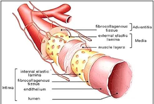
The walls of large vessels such as arteries consist of three concentric layers: an inner intima, an intermediate media and an outer adventitia (Figure 1.1). Regardless of the organization of these layers, the main constituents of blood vessel walls are endothelial cells (ECs), smooth muscle cells (SMCs) and the extracellular matrix (ECM). The intimal layer is attached to the basement membrane rich in collagen IV and laminin. This layer consists of a monolayer of specialized ECs, which forms a tight non-thrombogenic/anti-thrombogenic barrier between the lumen and the rest of the vessel wall. Vascular ECs experience shear stress in vivo, which ranges between 10 and 20 dynes/cm2 for straight arteries of uniform geometry. For non-uniform geometries (branches and arches), the shear stress can be as high as 50 dynes/cm2 with pulsatile flow (Papaioannou et Stefanadis, 2005). The intimal layer plays a role not only in preventing unwanted clot formation, but also prevents infection and inflammation of the underlying tissue.
The acellular and dense elastin layer, also known as the internal elastic lamina, separates the intimal layer from the medial layer. This muscular layer of the artery consists mainly of SMCs, collagen Type I and III, and a lesser amount of other proteins and proteoglycans. The collagen matrix and the SMCs in the intermediate media are aligned circumferentially along the axis of the blood vessel. Vessel contraction or dilation is caused by the stimulation of SMCs by signals from ECs of the lumen or directly by cytokines. Another dense elastin layer, the external elastic lamina, separates the intermediate media from the outermost layer of the vessel wall, i.e. the outer adventitia. The adventitia consists of a loose collagen matrix with embedded fibroblasts and vasa vasorum, which serves to anchor the blood vessel to the surrounding tissue and to provide additional structural support.
Figure 1.1. Schematic view of the organization of the three layers (intima, media and adventitia) of an artery. Taken from
(Muscle anatomy of the body, 2014).
1.1.2 Vascular injury
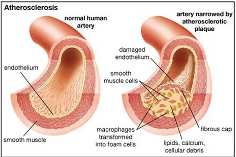
The most common reason for vessel failure is atherosclerosis, which is an inflammatory disease that causes plaque build-up beneath the intimal layer of the vessel wall. This plaque is formed by the infiltration of monocytes into the intima, and a resulting increase in the migration, proliferation, and secretary activity of the vascular SMCs. The blood vessel lumen narrows as the plaque grows (see Figure 1.2) and calcifies, leading to a decrease in blood flow to the downstream tissues. Plaque rupture and subsequent clot formation can eventually lead to infarction of the downstream tissue (Stary et al., 1995).
Figure 1.2. Schematic view of narrowing artery due to atherosclerotic plaque. Taken from (Merck, 2014).
Another possible result of atherosclerosis is the abnormal permanent dilation of the aorta, which leads to the formation of an aneurysm (Sakalihasan, Limet et Defawe, 2005; Zankl et al., 2007). Aortic aneurysms commonly occurred in three different locations, which are classified as abdominal aortic aneurysm (AAA), thoracic aneurysm and thoracic abdominal aneurysm. Of those aneurysms, AAA is leading cause of death in the aging population. It is typically either fusiform or saccular. Fusiform aneurysms present as a fairly uniform shape with symmetrical dilation that involves the full circumference of the aortic wall while saccular aneurysms present as localized dilation that appear as an outpouching of only a portion of the aortic wall (Adam van der Vliet et Boll, 1997).
There are three main pathophysiological mechanisms, such as inflammation, proteolysis and apoptosis, involved in the development of abdominal aortic aneurysms. AAA is mostly associated with severe atherosclerosis, which is characterized by the presence of inflammatory cells (Jonasson et al., 1986) that are recruited from blood and neovascularization processes in the media layer forming a lymphomonocytic infiltrate (Herron et al., 1991; Holmes et al.; Shah, 1997). The second mechanism for the development of AAA involves proteolytic degradation of elastin fibers and collagen by matrix
metalloproteinases (MMPs) that are either activated by other MMPs or plasmin (Carrell et al., 2002; Defawe et al., 2003; Rao, Reddy et Cohen, 1996; Thompson et Parks, 1996). The third and most significant mechanism leading to AAA involves the reduction of the density of smooth muscle cells in the media layer by the apoptotic process (Lopez-Candales et al., 1997). Altogether, the mechanisms leading to AAA suggest that the presence of a smooth muscle cell layer in the aortic wall is important, since VSMCs protect against inflammatory and proteolytic processes and also play a key role in repair processes of the aneurysms through localized expression of numerous extracellular matrix proteins and protease inhibitors (Allaire et al., 2002).
1.1.3 Vascular prostheses and their limitations
When stenting is not an option, the use of autologous vessels, including saphenous veins and mammary arteries, remains the standard procedure for the replacement of coronary arteries. However, one third of patients do not have veins suitable for grafting due to pre-existing vascular disease and vein stripping or vein harvesting for prior vascular procedures (Edwards, Holdefer et Mohtashemi, 1966; Veith et al., 1979). Finally, the harvest of autologous vessels causes significant morbidity and surgical costs. All of these factors contribute to a clinical requirement for readily available and functional synthetic small-diameter vascular grafts. Therefore, there is an increasing need to develop small-small-diameter vascular vessels for bypass surgery and other vascular reconstructive procedures. In addition, vascular grafts are needed for surgery performed for vascular trauma, aneurysms, and organ transplantation.
The most common method for the treatment of AAA involves traditional open surgery and endovascular aneurysm repair (EVAR). Surgical procedure involves the replacement of the walls of the aneurysm with a synthetic graft, whereas EVAR using stent grafts is an alternative to surgical procedure (see Figure 1.3 B). SGs, also called covered stents, are made of a polymeric tubular structure supported by metallic struts and are inserted by catheter to exclude blood flow from the aneurysmal sac and therefore prevent further enlargement or aneurysm rupture. EVAR is increasingly being used due to several
advantages such as its minimally invasive nature, reduced expense compared to conventional surgery and reduced recovery time and morbidity. However, this procedure is not free of complications that potentially occur during and after the EVAR procedure, which are mainly due to poor healing around the SG and lack of fixation into the surrounding vessel.
Figure 1.3. Schematic of (A) commercially available ePTFE vascular grafts (GORE-TEX) for coronary artery bypass and (B) stent graft
placement for the repair of EVAR (Biotextiles, 2014).
Current vascular grafts and stent grafts are generally made of woven polyethylene terephthalate (PET, Dacron) or expanded polytetrafluoroethylene (ePTFE) (see Figure 1.3).
PET: Poly (ethylene terephthalate), chemical structure represented as [O-C=O-C6H6
-O-C=O-CH2CH2]n, is a semi-crystalline polymer from the family of polyesters patented by
DuPont (Dacron ®) in 1950; (Chlupac, Filova et Bacakova, 2009)). PET's long chains are obtained from polycondensation of terephthalic acid and ethylene glycol. When PET is made into fibers, it is referred to commercially as Dacron. Dacron can be manufactured in either knitted or woven designs. Woven grafts have small pores, while knitted grafts have larger pores that promote greater tissue ingrowth and are more compliant. This polymer is generally strong, with a tensile strength of 170 MPa-180 MPa and a tensile modulus of 14,000 MPa.
These properties confer non-biodegradability and are stable for up to 30 years. However, Dacron grafts have been found to dilate over time (Boss et Stierli, 1993; Sporn et al., 2008).
PTFE: ePTFE, or Teflon, is a crystalline polymer composed of saturated carbon and fluorine atoms (-CF2-CF2-) patented by Gore (Gore-Tex) in 1969 (Chlupac, Filova et Bacakova, 2009). ePTFE is an expanded polymer that is obtained by a heating, stretching, and extruding process resulting in a non-textile porous tube composed of random-shaped solid membranes (nodes). This polymer is considered to be chemically inert and hydrophobic. ePTFE has a very low coefficient of friction, medium stiffness with a tensile strength of 21 MPa and tensile modulus of 413 MPa, and is much less flexible than PET (Palmaz, 1998; Ruben Y. Kannan et al., 2005). This polymer is relatively less prone to deterioration in biological environments compared to PET (Guidoin et al., 1993). The electronegative character of ePTFE is known to be helpful in minimizing its reaction with blood components (Palmaz, 1998; Ruben Y. Kannan et al., 2005).
These two materials were chosen for designing vascular prostheses due to their mechanical properties and relatively good hemocompatibility, which help to prevent thrombus formation. The current VG perform well as large-caliber substitutes, but their long-term patency is not satisfactory for small-caliber applications (<6 mm) such as in coronary and microvessel surgery (Hoenig et al., 2005; Kakisis et al., 2005; Kannan et al., 2005; Salacinski et al., 2001). This failure is mainly the result of an unfavorable healing process, surface thrombogenicity, lack of endothelial cells and anastomotic intimal hyperplasia caused by hemodynamic disturbances. Therefore, the use of synthetic small-diameter vascular grafts made of PET and ePTFE remain unsuccessful (Burkel, 1988; Greisler, 1990; Yeager et Callow, 1988; Zilla, von Oppell et Deutsch, 1993). Similarly, the use of current stent grafts for EVAR is limited by postoperative complications, which mainly arises due to surface-induced thrombosis, incomplete healing and lack of vascular tissue growth around the implant. These complications are mainly related to lack of favorable surface properties of implants for promoting VSMC adhesion, growth and resistance to apoptosis.
The comparison of Dacron vs. ePTFE by systematic evaluation and meta analysis of randomized controlled trials showed no evidence of an advantage of one material over the other (Roll et al., 2008). Host reactions to the synthetic vascular prosthesis start immediately after contact with blood circulation. The physico-chemical properties of the material surface, such as charge, energy, wettability and roughness, play a key role for the graft’s patency. It was demonstrated that the first event is the plasma protein adsorption/desorption process typical for any blood/material interface (Vroman et Adams, 1969). This process is followed by platelet recruitment, white blood cell and erythrocyte adhesion, and eventually endothelial and smooth muscle cell migration. Fibrin deposits (containing platelets and blood cells) usually form during the first few hours to days after implantation and are stabilized for 18 months with the formation of an inner compacted fibrin layer. Furthermore, fibrin is known to fill the interstices within the graft wall. Unfortunately, these steps are not followed by spontaneous endothelialisation, which would be required to reproduce the anti-thrombotic properties as described above. Only a few dispersed small islands of endothelialisation appeared on woven excised Dacron grafts (Wu et al., 1995) and knitted Dacron grafts during 1-11 years after implantation (Shi et al., 1997). ePTFE-based grafts face the same complications as Dacron when used for small-diameter blood vessels (Wu et al., 1995).
The presence of adsorbed proteins from blood plasma greatly influences cell attachment to synthetic surfaces. Proteins bind to surfaces depending on surface physico-chemical properties (Roach, Farrar et Perry, 2006) such as wettability, physico-chemical composition and surface charge. These properties can determine the composition, surface density and conformation of the adsorbed protein layers. A combination of interactions such as hydrophobic forces, electrostatic forces, hydrogen bonding and van der Waals forces is responsible for protein adsorption on material surfaces (Brash, 1996). Changing surface properties, for example increasing surface hydrophilicity, results in quantitative and qualitative variation in the composition of the adsorbed protein layer. Proteins usually adhere irreversibly on hydrophobic surfaces since such surfaces exert strong interaction with hydrophobic parts of the protein. This interaction causes protein deformation or denaturation or disruption of native conformation and therefore the exposition of cell-binding regions on proteins is altered. It has been recognized that albumin and fibrinogen (Wu et al., 2005)
adsorbs to hydrophobic surfaces, while adhesive proteins (Fn and Vn) preferentially adsorb to hydrophilic surfaces when surfaces are exposed to blood plasma or serum (Koenig, Gambillara et Grainger, 2003a; Kottke-Marchant, Veenstra et Marchant, 1996). It is generally observed that ECs adhere and spread moderately on hydrophilic surfaces, whereas EC adhesion is reduced or even absent on hydrophobic surfaces (Absolom, Hawthorn et Chang, 1988; van Wachem et al., 1987). Both Dacron and ePTFE grafts are hydrophobic, however ePTFE is more hydrophobic than PET (Chlupac, Filova et Bacakova, 2009). Therefore, these materials are prone to adsorb fibrinogen and albumin and unfavorable for the adsorption of cell-adhesive proteins, which may lead to platelet adhesion and activation with poor or no EC adhesion. Therefore it is important to improve surface chemical and biological properties to reduce thrombosis and promote desired cell adhesion and growth (ECs for vascular grafts and VSMCs for sent grafts). In the following sections various surface modification methods will be described.
1.2 Blood-material interactions
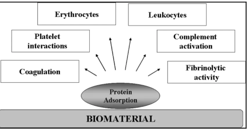
The majority of biomaterials used in blood-contacting devices are associated with many complications due to the interactions between blood and the material surface. Such interactions can ultimately lead to the failure of the device. This section will describe the mechanisms implicated in thrombus formation on biomaterials surfaces. As mentioned earlier, the introduction of foreign material into the body or blood causes immediate adsorption of blood proteins onto the surface and usually form a monolayer within seconds (Brash et Ten Hove, 1993; Courtney et Forbes, 1994). These interactions usually followed by platelet adhesion and activation, leukocyte adhesion, activation of the complement system, activation of blood coagulation and therefore thrombus formation (Eckmann et al., 2013; Gorbet et Sefton, 2004; Ratner et Bryant, 2004). As shown in Figure 1.4 (Courtney et Forbes, 1994), the body reacts to the layer of adsorbed proteins rather than the surface itself. Since the protein adsorption is the initial step of blood-material interactions, the protein adsorption phenomen is also described in the following sections.
Figure 1.4. Schematic shows a simplified view of the interaction of blood elements with biomaterial surface. Taken from (Courtney et Forbes, 1994).
1.2.1 Protein-surface interactions and their influence on protein adsorption
Proteins consist of long chain amino acids that are linked together by peptide bonds formed between the amino and carboxyl groups of adjacent amino acid residues. Proteins are also referred to as polypeptides, since amino acids polymerize to form protein through peptide bonds. The net charge on proteins can be positive, negative or neutral, depending on the composition of amino acids, pH of the solution and protein's isoelectric point. Protein adsorption can be described as the "accumulation” of protein at the material interface. Normally, protein adsorption on the surface takes place in a non-specific way, which means that the proteins are only "physically" attached to the surface. The amount of adsorbed protein on the surface depends on its concentration as well as protein-surface affinity (Barnthip et al., 2008).
Both the affinity and the rate of transport to the surface influence protein adsorption kinetics. The rate of protein diffusion is influenced by the size of proteins, with smaller proteins diffusing faster than larger ones. The size of the protein also determines the affinity of protein molecules. For example, larger proteins may readily adsorb to the material surface since they have more binding sites to interact with the surface. A number of other factors come into play to influence the affinity of protein adsorption, since proteins are composed of sequences of amino acids and they exhibit different properties. Protein properties such as
charge (depending on the pH of their environment), hydrophilicity, hydrophobicity and internal structure influence protein-surface affinity (David Richard Schmidt, 2009). For example, larger "soft" proteins (e.g. immunoglobulin (IgG), α-lactalbumin, β-casein and hemoglobin) that have a low structural stability are known to interact with higher affinity than smaller "hard" ones (α-chymotrypsin, ribonuclease, lysozyme and β-lactoglobulin) that have greater structural stability (Norde, 1996).
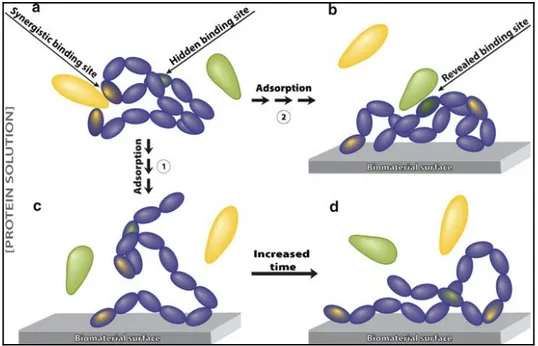
The structure of a protein also plays a key role in protein adsorption because specific conformation may expose specific binding domains to interaction with the surfaces. Protein may lose its specific activity when it undergoes a conformational change upon adsorption to a material surface; over a period of time pertinent protein unfolding and changes in protein activity may also occur as shown Figure 1.5. This schematic illustrates that; (a) the protein has a binding site that requires a specific structure, (c) upon protein adsorption, these conformational epitopes are no longer functional as they are far apart, (d) over a period of time, the adsorbed protein may continue to unfold, thereby exposing additional binding sites. and (b) the hidden biding site of protein may have been revealed but it becomes available for binding to another molecule once the protein has unfolded upon adsorption on the material surface (David Richard Schmidt, 2009).
In a multi-protein system, for example blood plasma, many proteins compete for the adsorption sites on the material surface. Initially, protein adsorption is controlled by protein diffusion. Therefore, in the early stages, the protein concentration and size play a critical role (Barnthip et al., 2009; Krishnan, Siedlecki et Vogler, 2004; Noh et Vogler, 2007); smaller proteins present at higher concentration adsorb more than larger ones at lower concentration. However, over a period of time, proteins of higher surface affinity will displace those of lower affinity regardless of protein concentration and size. This exchange phenomena is known as the Vroman effect (Leonard et Vroman, 1991; Noh et Vogler, 2007). For example, when this phenomenon was verified for plasma proteins containing albumin, IgG and fibrinogen (Fg) (Brash, 1996; Jung et al., 2009; Noh et Vogler, 2007), it was noticed that initially adsorbed Fg had been displaced over time by other higher affinity and low concentration proteins such as high molecular weight kininogen (Brash et Ten Hove, 1993).
Figure 1.5. Schematic view of protein conformational changes upon adsorption on the material surfaces. Taken
from (David Richard Schmidt, 2009).
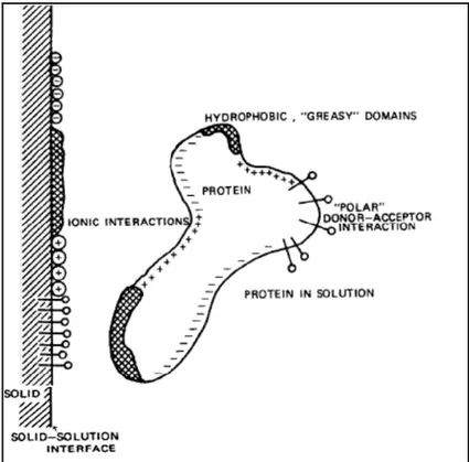
While the properties of individual proteins are important for protein adsorption, material surface properties such as hydrophilicity, hydrophobicity, topography, surface charge and chemistry (Andrade et Hlady, 1986) also decide the fate of protein adsorption. Figure 1.6 shows the interactions between a protein and the surface that have different binding domains. It is worth noting that water molecules adsorb to the material surface prior to protein adsorption. In the case of hydrophobic surfaces, a shell of water molecules forms in which water molecules prefer to interact with each other rather than interacting with the hydrophobic surface. One hypothesis postulates that the shell of these surrounding water molecules represents a fairly ordered scenario with a decreased level of entropy; disruption of this layer with proteins is energetically favorable due to a concomitant increase in entropy (David Richard Schmidt, 2009). The increase in entropy is the primary driving force for protein adsorption on hydrophobic surfaces. Although it is difficult to predict how surface hydrophobicity affects protein adsorption for a specific system, in general, enhanced protein adsorption and conformational changes are observed as surface hydrophobicity increases (Gray, 2004). Depending on the charged areas of both the surface
and the protein, surface charge has an effect of either attracting or repelling proteins. For example, a net negative charge on the material surface reduces the adsorption of serum proteins, since the majority of blood serum proteins are negatively charged (in physiological condition).
Figure 1.6. A schematic view of protein-surface interactions. Both the surface and the protein have a
number of interacting domains with charged, hydrophobic and polar character. Image taken from
(Andrade et Hlady, 1986).
Protein adsorption is also strongly influenced by topographical features on a material surface. Increased surface roughness may lead to a net increase in protein absorption on the material surface, since roughness provides more surface area for protein adsorption (Rechendorff et al., 2006). Finally, changes in surface chemistry dictate the types of bonds between protein and material surface and thus affect protein adsorption. In the literature, the impact of several surface functional groups on protein adsorption was mentioned. Non-polar
and hydrophobic groups such as methyl (CH3) groups are known to tightly bind fibrinogen (a
key protein involved in platelet adhesion and thrombus formation) and immunoglobin (IgG; an antibody protein involved in the immune response). A material surface that functionalized with -OH groups is known to increase surface hydrophilicity and thus reduce the affinity of plasma proteins. Amine (NH2) groups are found to strongly bind fibronectin and other
proteins and induce adhesion of platelets and several cell types. These functional groups are also known to trigger acute inflammatory reactions in vivo. (Wang et al., 2004). Carboxyl (– COOH) groups are negatively charged in the presence of blood serum and aqueous protein solutions and are hydrophilic. These groups are known to interact preferentially with vitronectin and albumin (Wang et al., 2004; Weis et al., 2004). It is important to note that these generalized observations may not be true for all cases and may vary depending on experimental conditions and the type of protein solutions. For example, a surface that is activated with multiple functional groups may have a different effect on protein adsorption compared to individual functional groups. In the case of mixed SAMs of –NH2 and –COOH
functional groups (at equal molar fractions), reduced fibrinogen adsorption (Chuang et Lin, 2007) and therefore the lowest platelet adhesion was observed (Thevenot, Hu et Tang, 2008; Wang et al., 2004). It is also important to note that, over time, the presence of water and other molecules in the surrounding environment may modify the activity of functional groups on the material surface (Wang et al., 2004; Weis et al., 2004).
The environment in which protein adsorption occurs is also an important factor that may alter protein adsorption and conformation. Temperature significantly above room temperature can increase protein adsorption. Another important factor is pH condition, which can affect protein adsorption because changes in the charge of both the material surface and the protein molecule may lead to variations in electrostatic interactions (Brash et Ten Hove, 1993).
1.2.1.1 Adsorption of serum proteins
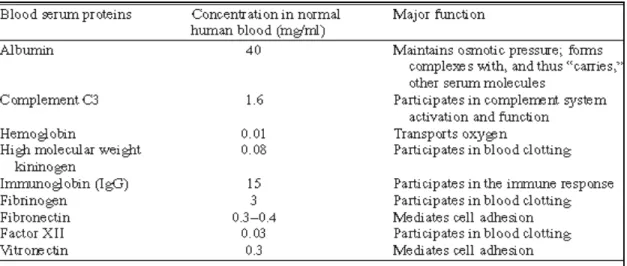
The adsorption of serum proteins plays a critical role in promoting platelet and cell adhesion and other biological functions. There are more than 150 varieties of proteins found in human blood serum. The most widely studied proteins and their biological function are listed in the following Table 1.1. Some studies in the literature reported that serum protein adsorption on glass surfaces follows the sequence as albumin first, followed by IgG, fibrinogen, fibronectin, factor XII, and high molecular weight kininogen (Boland et Weigel, 2006; Ellis et al., 1999). Since albumin is the smallest protein and present in high concentration in serum, it adsorbs first on the material surface. Albumin, however, has a relatively low affinity compared to other proteins present in the serum, therefore, over a period of time, it is partially replaced by larger and higher-affinity proteins such as fibrinogen (which is a key molecule in promoting platelet recruitment) (Boland et Weigel, 2006; Ellis et al., 1999).
Table 1.1. Major constituents of human blood serum and their biological functions. Taken from (David Richard Schmidt, 2009).
1.2.2 Thrombus formation
The blood circulatory system is a closed-loop system and it is responsible for the distribution of essential nutrients throughout the body. Injury to the healthy blood vessel leads to immediate thrombus formation to seal the damaged site and therefore to prevent
blood leakage. This process is an essential mechanism to maintain circulation integrity. The accumulation of circulating platelets will take place at the site of injury during thrombus formation and the coagulation system produces thrombin and fibrin to stabilize the clot.
In the native vasculature, after vessel injury, platelet aggregation occurs by the adhesion of exposed collagen in the sub-endothelial matrix. The initial platelet adhesion is mediated by membrane receptors, such as glycoprotein VI and glycoprotein Ib, that bind to collagen and von Willebrand factor, respectively (Fressinaud et al., 1994; Mackman, 2008; Ruggeri, 1997). Platelet adhesion is also known to be mediated by integrin receptors α2β1 and αIIbβ3, which bind to collagen and fibrinogen/fibrin, respectively (Bennett, Berger et Billings, 2009; Mackman, 2008; McCarty et al., 2004). The adsorption of these proteins to blood-contacting devices or materials initiates platelet adhesion and therefore platelet activation will occur. Alternatively, soluble factors can activate platelets through binding to its receptors. For example, the tissue factor (TF) pathway leads to thrombin production, and subsequently thrombin cleaves protease-activated receptor 1 (Par-1) on the platelet surface and ultimately activates platelets. Another example is that thromboxane A2 (TXA2) and ADP can bind to their respective receptors on platelets and activate platelets (Davie, Fujikawa et Kisiel, 1991; Furie et Furie, 2008; Mackman, 2008). Both mechanisms (platelet adhesion and the exposure to soluble agonists) are known to be capable of initiating platelet activation individually. However, the relative contribution of each mechanism is still unknown. In general, platelet activation can be recognized by a rapid change in platelet geometry and the release of platelet granules containing a variety of strong chemical agonists that amplify the activation and aggregation of platelets (Blockmans, Deckmyn et Vermylen, 1995; Ruggeri, 2009). The activation of platelets leads to thrombus formation as well as inflammatory responses.
1.2.3 Blood coagulation
Blood coagulation involves a series of cascading events that leads to formation of thrombin and therefore fibrin clot. Blood coagulation follows two separate pathways, namely, the intrinsic pathway (or contact phase pathways) and the extrinsic pathway. Both