HAL Id: dumas-00741484
https://dumas.ccsd.cnrs.fr/dumas-00741484
Submitted on 16 Oct 2012HAL is a multi-disciplinary open access archive for the deposit and dissemination of sci-entific research documents, whether they are pub-lished or not. The documents may come from teaching and research institutions in France or
L’archive ouverte pluridisciplinaire HAL, est destinée au dépôt et à la diffusion de documents scientifiques de niveau recherche, publiés ou non, émanant des établissements d’enseignement et de recherche français ou étrangers, des laboratoires
Indocyanine green angiography in preoperative
perforators mapping for anterolateral thigh flap:
anatomical study
Clotilde Ochala
To cite this version:
Clotilde Ochala. Indocyanine green angiography in preoperative perforators mapping for anterolateral thigh flap: anatomical study. Human health and pathology. 2012. �dumas-00741484�
AVERTISSEMENT
Ce document est le fruit d'un long travail approuvé par le
jury de soutenance et mis à disposition de l'ensemble de la
communauté universitaire élargie.
Il n’a pas été réévalué depuis la date de soutenance.
Il est soumis à la propriété intellectuelle de l'auteur. Ceci
implique une obligation de citation et de référencement
lors de l’utilisation de ce document.
D’autre part, toute contrefaçon, plagiat, reproduction illicite
encourt une poursuite pénale.
Contact au SICD1 de Grenoble :
thesebum@ujf-grenoble.frLIENS
LIENS
Code de la Propriété Intellectuelle. articles L 122. 4
Code de la Propriété Intellectuelle. articles L 335.2- L 335.10
http://www.cfcopies.com/V2/leg/leg_droi.phpUNIVERSITE JOSEPH FOURIER FACULTE DE MEDECINE DE GRENOBLE
Année 2012 N°
Indocyanine green angiography in preoperative perforators mapping for
anterolateral thigh flap: anatomical study.
THESE
PRESENTEE POUR L’OBTENTION DU DOCTORAT EN MEDECINE DIPLÔME D’ETAT
Clotilde OCHALA Née le 3 janvier 1984 à Chenôve
Thèse soutenue publiquement à la faculté de médecine de Grenoble Le 6 avril 2012
Devant le jury composé de :
Monsieur le Professeur Jacques LEBEAU, président du jury Monsieur le Professeur François MOUTET
Monsieur le Professeur Philippe CHAFFANJON
Monsieur le Docteur Georges BETTEGA, directeur de thèse Madame le Docteur Alexandra FORLI
A notre Maître et président de thèse,
Monsieur le Professeur Jacques LEBEAU,
Vous me faites l’honneur de présider cette thèse et de juger mon travail,
Veuillez trouver l’expression de mon profond respect et de ma sincère gratitude pour votre confiance et votre enseignement de grande qualité.
Aux membres du jury,
Monsieur le Professeur François MOUTET,
Je vous remercie de votre grande accessibilité et de vos enseignements lors des deux semestres passés dans votre service. Soyez assuré de mon admiration et de ma reconnaissance.
Monsieur le Professeur Philippe CHAFFANJON,
Je vous remercie de m’avoir ouvert les portes du laboratoire d’anatomie pour ce travail de dissection. Veuillez trouver ici le témoignage de ma gratitude.
Monsieur le Docteur Georges BETTEGA,
Je te remercie pour ton aide, ta grande disponibilité, ta rigueur et tes précieux
conseils au cours de ce travail et tout au long de mon internat. C’est un grand plaisir de travailler avec toi et d’apprendre à tes côtés.
Madame le Docteur Alexandra FORLI,
Je te remercie pour ton professionnalisme, ta patience et ta gentillesse. Tu es, pour moi, plus qu’une chef, un modèle.
A mes parents, qui font tout pour leurs enfants et qui m’ont entourée tout au long de mon parcours. Je vous remercie pour l’amour que vous savez nous donner à chaque instant.
Je vous aime plus que tout.
A Pierre, mon mari, mon soutien, mon soleil, mon amour…
A Pounette, ma sœur adorée, qui est toujours là pour moi.
A Paul, mon frère, pour tous ces instants heureux passés ensemble et ses câlins un peu « brutaux ».
Je vous aime tellement.
A Sophie, ma belle sœur préférée, à mes petits neveux chéris Arthur et Victor, qui nous apportent un grand bonheur chaque jour.
A mes « copines de la vie », Marie, Bertille, Hélène, Jenni et Cécile, pour tous ces
moments merveilleux d’amitié, ces grosses fiestas, ces vacances entre filles et tout ce qu’il nous reste encore à vivre ensemble.
A Emmanuelle, mon amie de toujours.
nous éloigneront pas.
A tous mes amis.
A tous mes co-internes, et particulièrement à Antoine, Alessandro, Mahmoud et Julien avec qui j’ai débuté en chirurgie plastique.
Au Dr Michel PENIN qui m’a donné le goût pour la chirurgie plastique. Merci pour l’expérience que tu m’as transmise et les bons moments passés comme aide opératoire.
A toutes les équipes médicales et paramédicales avec lesquelles j’ai travaillé, en particulier, l’équipe de chirurgie viscérale d’Annecy, l’équipe de chirurgie de la main (spécialement Irène et Isabelle) et l’équipe de chirurgie maxillo-faciale et plastique du CHU de Grenoble.
CONTENTS
I. List of abbreviations………. 11
II. Introduction………. 12
III. Material and methods………. 14
IV. Results……… 23
V. Discussion……… 28
VI. Conclusion……….. 34
References………. 36
Appendix I: the « perforator flap » concept……….. 40
Appendix II: the ALT flap………. 54
Appendix III: indocyanine green angiography……….. 59
The Hippocratic oath……….. 68
I. LIST OF ABBREVATIONS
ALT: anterolateral thigh flap
CTA: computed tomographic angiography ICG: indocyanine green
ASIC: anterosuperior iliac crest
DAP: distance between ASIC and patella DIEP: deep inferior epigastric perforator flap SGAP: superior gluteal artery perforator flap TAP: thoracodorsal artery perforator flap IGAP: inferior gluteal artery perforator flap
II. INTRODUCTION
The anterolateral thigh flap (ALT) described by Song et al. in 1984 [1] is a perforator flap harvested from the anterolateral side of the thigh. This fasciocutaneous flap is vascularized by one or more septo- or musculocutaneous perforator, originating from the descending branch of the thigh lateral circumflex artery.
It has become increasingly popular due to its versatility and minimal donor-site morbidity [2]. But the perforators present considerable anatomical variation [3] and their locations are difficult to predict preoperatively.
Perforator topography was classified by Shieh [4] et al. according to origin and direction: • type 1: musculocutaneous perforators with vertical direction, originating from the descending branch of the lateral circumflex artery (56.8%);
• type 2: musculocutaneous perforators with horizontal direction, originating from the transverse branch of the lateral circumflex artery (27%);
• type 3: septocutaneous perforators with vertical direction, originating from the descending branch of the lateral circumflex artery (10.8%);
• type 4: septocutaneous perforators with horizontal direction, originating from the transverse branch of the lateral circumflex artery (5.4%).
Musculocutaneous perforators are more difficult to dissect and a magnifying lens is recommended.
In most cases (93%), perforators are found inside a circle drawn around the middle of a line drawn between the anterosuperior iliac crest and the superolateral edge of the patella [5]. Imaging is strongly advised, although some surgeons consider that careful surgical
Accurate perforator mapping reduces operating time, especially when there are no perforators in a thigh (5.4% of cases [6]) and another flap has to be used instead. Another merit of this pre-surgical assessment is that, depending on the location of cutaneous perforators, the flap design can be customized preoperatively to meet reconstructive requirements [7].
A variety of methods are used to identify perforators: acoustic Doppler, color Doppler,
magnetic resonance angiography [8], computed tomographic angiography (CTA), recovery-enhanced thermography [9].
Hand-held Doppler has been used for decades to plan flap surgery [10]. It is inexpensive, portable, and rapid. But the origin, direction, and caliber of perforators cannot be determined. Color Doppler flowmetry offers accurate information on the number and location of cutaneous perforators [11]. It is time-consuming (30 to 40 min) and the machine is expensive. The surgeon harvesting the flap is the most apt at performing an accurate and practical flap assessment; furthermore this assessment requires experience.
CTA is considered to be the "gold standard" examination because of its availability, and precision in identifying perforators (number, type, location, caliber).
CTA is more specific than Doppler to locate perforators [12,13]. Doppler cannot differentiate superficial vessels running within the subcutaneous tissue from real perforators. CTA reduces the inter-observer variability, which is high with Doppler.
Near-infrared angiography with indocyanine green (ICG) dye seems to be an interesting technology for perforator detection. But in France, it is not validated yet for this indication. ICG is widely used in ophthalmology, cardiology, hepatology. In plastic surgery, it has been used mostly to assess flap perfusion [14]. Its ability to localize skin perforators was also demonstrated [15]. Its accuracy has not been yet verified in clinical practice, and compared with CTA or Doppler. The authors of one study found a full correlation among perforators identified with near-infrared fluorescence angiography, x-ray angiography, and anatomic dissection, on 8 pigs [16].
III. MATERIAL AND METHODS
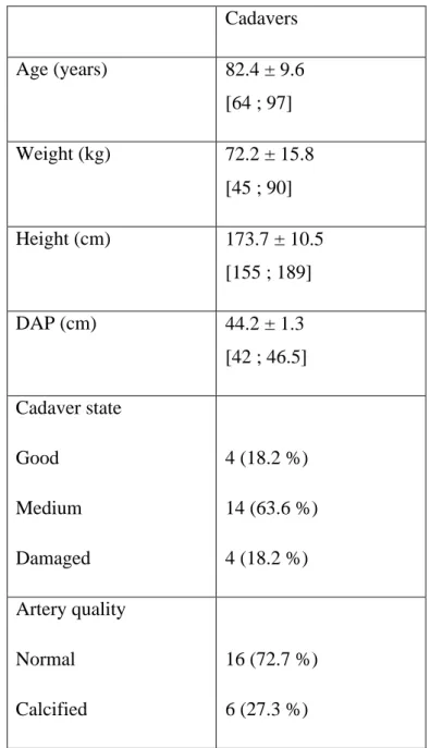
22 cadaveric thighs (11 cadavers) were studied (Table I). The age of cadavers ranged from 64 to 97.
Cadavers Age (years) 82.4 ± 9.6 [64 ; 97] Weight (kg) 72.2 ± 15.8 [45 ; 90] Height (cm) 173.7 ± 10.5 [155 ; 189] DAP (cm) 44.2 ± 1.3 [42 ; 46.5] Cadaver state Good Medium Damaged 4 (18.2 %) 14 (63.6 %) 4 (18.2 %) Artery quality Normal Calcified 16 (72.7 %) 6 (27.3 %)
It was followed by venous drainage of Arthil 26 through the jugular vein.
The cadavers were immersed in a large tub with a mixture of formaldehyde, ethanol, and glycerin for 15 days to complete preservation.
Then the cadavers were kept in a fridge at 4 degrees for 3 to 4 months before use. None of the cadavers used had any scar from a previous thigh surgery.
We drew up a binary classification of arteries according to their calcification degree. Good arteries were labeled zero and calcified arteries one.
The quality of cadavers was labeled zero when the body was very well preserved, one for a medium preservation, and two for a damaged body.
We considered that the state of preservation was good when soft tissues were flexible and easy to dissect. On the contrary, damaged bodies were those with more rigid tissues.
Cadavers were put in the supine position.
The line between the anterosuperior iliac crest (ASIC) and the superolateral edge of the patella was drawn with a marker pen, and also the inguinal ligament outline.
A minimal dissection was performed in the femoral triangle (of Scarpa) to expose femoral vessels.
This triangular area is limited above by the inguinal ligament (between ASIC and pubic spine), laterally by the sartorius muscle, and medially by the adductor longus. The apex of this triangle is formed by the intersection of these two muscles.
The femoral nerve, femoral artery, and femoral vein are located under the skin and the femoral fascia.
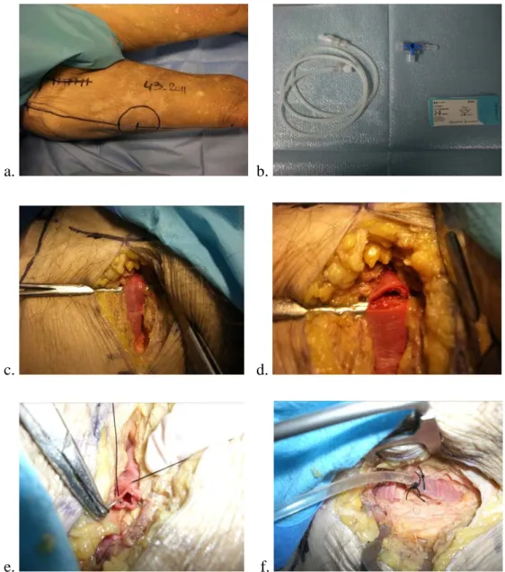
The skin was incised vertically just below the inguinal ligament. The proximal end of the femoral artery was exposed and catheterized with a silicone tube and a three-way tap. The tube was fixed with a purse-string suture (Figure 1).
This catheter was used for ICG angiography and for CTA.
a. b.
c. d.
e. f.
Figure 1: a. drawing for incision, b. material, c. exposure of the femoral artery, d. incision of the femoral artery, e. purse-string suture, f. silicone tube fixed in the femoral artery.
1) ICG angiography
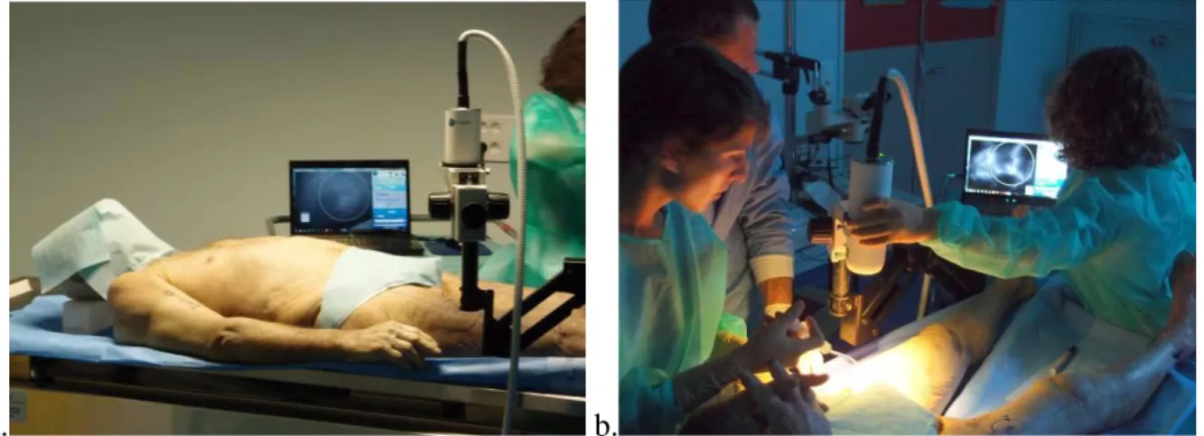
The cadavers are kept in the supine position. The Fluobeam system hand probe was placed 20 to 40 cm above the skin, on an articulated arm. 4ml of Infracyanine (5mg/ml) were injected, followed by 20 ml of saline. Fluobeam system recording was started at the same time (Figure 2).
Images and data were recorded on a dedicated computer (Fluobeam FB 800, Fluoptics, Grenoble, France). After two seconds, perforators appeared as fluorescent spots on the thigh (Figure 3).
a. b.
Figure 2: a. cadaver in the supine position with the Fluobeam fixed over the thigh, b. Fluobeam system recording begins, data is stored on a dedicated computer.
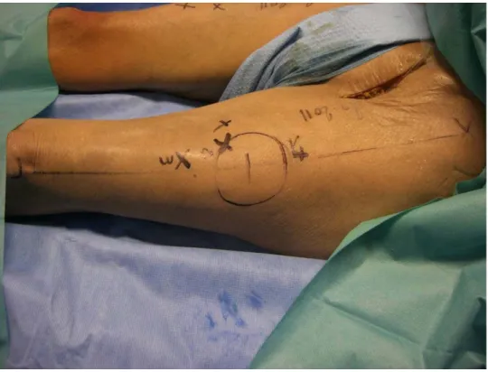
The location of each perforator was marked immediately by a cross on the skin.
Each perforator was located according to an orthogonal plan defined by the ASIC-patella line and a perpendicular to this line. The (x,y) coordinates were measured in centimeters (Figure 4).
Figure 3: fluorescent spots on the thigh corresponding to perforators.
The femoral artery was rinsed with saline and 4ml of contrast iodine were injected afterwards.
Figure 4: each perforator was located by coordinates (x,y), x corresponding to the thigh anatomic axis and y to its perpendicular. Measures were in centimeters.
2) CTA
The thighs were detached above the ASIC and below the knee to keep our marks. The popliteal artery was ligatured to prevent leaking below the knee.
CTA was performed with a Phillips Brillance 64 CT scan. 20 ml of iodine solution, diluted to one third, were injected (Omnipaque, 350mg I/ml) in the catheter. Images were reconstructed in MIP (maximum intensity projection) and VRT (volume rendering tissue) and analyzed by the same radiologist (FT). The collimation was 0.67mm and the slices were 1mm thick, with a specific program for perforators (Phillips Portal station).
The perforators were located using the same marks as for ICG angiography (Figure 5).
c. d.
e. f.
Figure 5: each perforator detected by CTA was defined by coordinates (x, y) with the same marks used for angiography. a. reconstruction of arterial femoral vessels, b. two perforators located on the thigh by the radiologist, c. transversal slice, the perforator can be seen just under the skin d. measurement of coordinates of the first perforator artery (22.3 ; +1.1), e. transversal slice, perforator with an intramuscular path, f. measurement of the second perforator artery coordinates (29.7 ; -2.2).
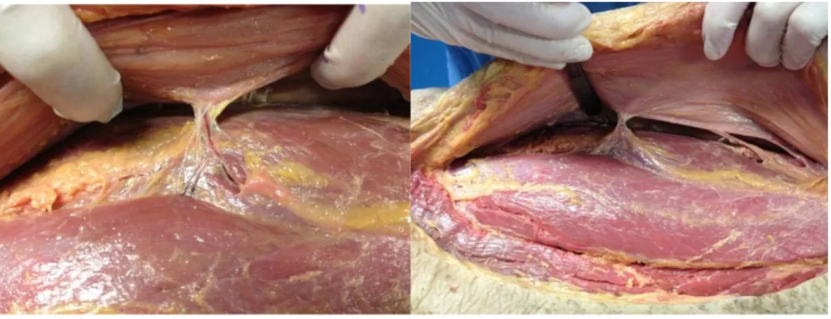
3) Cadaveric dissection
After ICG angiography and CTA, thighs were dissected at the anatomy laboratory.
The incision was made on the medial side of the thigh and went through skin, subcutaneous tissue, and muscle fascia. The deep layer of the flap was dissected medially carefully to expose skin perforators. Once the perforator was identified, its projection was marked with a pen on the skin. It was localized using the previous marks (ASIC-patella). The (x,y) coordinates were measured in centimeters (Figure 6).
Perforators with a diameter inferior to 1mm were excluded.
Figure 6: cadaveric dissection. The dissection was performed under the fascia to find perforators the projection of which was then marked on the skin by a cross.
The localization of perforators determined by CTA and fluorescence was compared with the gold standard given by anatomical dissection.
We used the Chi2 test or Fisher’s exact test (when Chi2 could not be used) to evaluate the number of perforators identified by each examination, and the correlation between these methods and anatomical dissection.
Sensitivity, specificity, positive predictive value, and negative predictive value were measured according to the recorded data.
IV. Results
Indocyanine green angiography detected 97 perforators on 22 cadaveric thighs, CTA detected 11 perforators. We found 76 perforators with anatomical dissection.
We considered that a perforator detected in CTA or in fluorescence was the same as the one found by dissection when the difference between coordinates (x,y) was inferior or equal to 0.5cm.
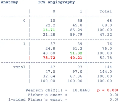
Indocyanine green angiography was correlated to anatomy according to the Chi2 test.
Anatomy ICG angiography
| 0 1 | Total 0 | 10 58 | 68 | 22.2 45.8 | 68.0 | 14.71 85.29 | 100.00 | 21.28 59.79 | 47.22 1 | 37 39 | 76 | 24.8 51.2 | 76.0 | 48.68 51.32 | 100.00 | 78.72 40.21 | 52.78 Total | 47 97 | 144 | 47.0 97.0 | 144.0 | 32.64 67.36 | 100.00 | 100.00 100.00 | 100.00 Pearson chi2(1) = 18.8460 p = 0.000 Fisher's exact = 0.000 1-sided Fisher's exact = 0.000
Table II: sensitivity and specificity of indocyanine green angiography are in green. p<0.05 shows that anatomy and ICG angiography are correlated.
The positive predictive value was 40.2% and the negative predictive value was 21.3%.
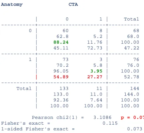
CTA was not correlated with anatomy. We cannot reject the independence of these two techniques, according to the Chi2 test (p>0.05).
The sensitivity of CTA was 3.9% and the specificity was 88.2% (Table III).
The positive predictive value was 27.3% and the negative predictive value was 45.1%.
Anatomy CTA | 0 1 | Total 0 | 60 8 | 68 | 62.8 5.2 | 68.0 | 88.24 11.76 | 100.00 | 45.11 72.73 | 47.22 1 | 73 3 | 76 | 70.2 5.8 | 76.0 | 96.05 3.95 | 100.00 | 54.89 27.27 | 52.78 Total | 133 11 | 144 | 133.0 11.0 | 144.0 | 92.36 7.64 | 100.00 | 100.00 100.00 | 100.00 Pearson chi2(1) = 3.1086 p = 0.078 Fisher's exact = 0.115
1-sided Fisher's exact = 0.073
Table III: sensitivity and specificity of CTA are in green. p>0.05 shows that anatomy and CTA were independent.
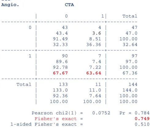
ICG Angio. CTA | 0 1| Total 0 | 43 4 | 47 | 43.4 3.6 | 47.0 | 91.49 8.51 | 100.00 | 32.33 36.36 | 32.64 1 | 90 7 | 97 | 89.6 7.4 | 97.0 | 92.78 7.22 | 100.00 | 67.67 63.64 | 67.36 Total | 133 11 | 144 | 133.0 11.0 | 144.0 | 92.36 7.64 | 100.00 | 100.00 100.00 | 100.00 Pearson chi2(1) = 0.0752 Pr = 0.784 Fisher's exact = 0.749
1-sided Fisher's exact = 0.510
Table IV: correlation between ICG angiography and CTA (p>0.05). ICG and CTA are independent.
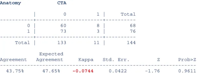
The concordance correlation coefficient evaluated with a Kappa was very low (<0.00) (Table V).
Indocyanine green angiography was more concordant with anatomy than CTA. ICG angiography is more effective to locate perforators.
Anatomy ICG angiography
| 0 1 | Total 0 | 10 58 | 68 1 | 37 39 | 76 Total | 47 97 | 144 Expected
Anatomy CTA | 0 1 | Total 0 | 60 8 | 68 1 | 73 3 | 76 Total | 133 11 | 144 Expected
Agreement Agreement Kappa Std. Err. Z Prob>Z 43.75% 47.65% -0.0744 0.0422 -1.76 0.9611
Table V: concordance correlation coefficient of ICG angiography and CTA with anatomy.
We evaluated the relationship between the cadaver's state and results.
22.7% of perforators were found by ICG angiography when the cadaver was well preserved, 58.6% for a medium preservation, and 18.6% for damaged bodies (Table VI).
ICG angio. Cadaver state
| 0 1 2 | Total 0 | 8 30 9 | 47 | 9.8 28.4 8.8 | 47.0 | 17.02 63.83 19.15 | 100.00 | 26.67 34.48 33.33 | 32.64 1 | 22 57 18 | 97 | 20.2 58.6 18.2 | 97.0 | 22.68 58.76 18.56 | 100.00 | 73.33 65.52 66.67 | 67.36 Total | 30 87 27 | 144 | 30.0 87.0 27.0 | 144.0 | 20.83 60.42 18.75 | 100.00 | 100.00 100.00 100.00 | 100.00 Pearson chi2(2) = 0.6271 p = 0.731
CTA Cadaver state | 0 1 2 | Total 0 | 27 81 25 | 133 | 27.7 80.4 24.9 | 133.0 | 20.30 60.90 18.80 | 100.00 | 90.00 93.10 92.59 | 92.36 1 | 3 6 2 | 11 | 2.3 6.6 2.1 | 11.0 | 27.27 54.55 18.18 | 100.00 | 10.00 6.90 7.41 | 7.64 Total | 30 87 27 | 144 | 30.0 87.0 27.0 | 144.0 | 20.83 60.42 18.75 | 100.00 | 100.00 100.00 100.00 | 100.00 Pearson chi2(2) = 0.3070 p = 0.858
Table VI: number of perforators detected with ICG angiography or with CTA in well-preserved, medium preservation, or damaged body.
27.3 % of perforators were detected with CTA when the cadaver was in a good state, 54.6% with medium preservation, and 18.2% with damaged bodies.
There was no statistically significant difference. The cadaver's state was not a bias in this study.
V. DISCUSSION
ICG angiography localized ALT perforators on cadavers, with a good precision for the surgeon.
It had a good sensitivity, 51.3%. It allowed detecting very tiny perforators, which are sometimes, unsuitable for microsurgery. Several perforators were located by ICG on each thigh, whereas CTA could not always locate perforators.
ICG specificity was low, 14.7%. This can be explained because ICG cannot discriminate subcutaneous vessels from perforators. That is why we found 97 perforators with ICG and only 67 in anatomical dissection. All the fluorescent spots did not correspond to perforators. The concordance correlation coefficient between anatomy and ICG was average. That is to say the results found with ICG were concordant with anatomical dissection data.
On the contrary, CTA was not effective to map perforators on anatomical pieces.
CTA had a good specificity (88.2%) but a very low sensitivity (3.9%). CTA could discriminate perforators from others vessels because of its precision. CTA identified accurately the path and type of perforators. But it did not detect tiny perforators.
In this study, CTA detected only 11 perforators on 22 thighs, whereas in anatomy we always found one or more perforators on every thigh.
CTA results found were not concordant with those of anatomical dissection. If anatomy was an imaging technique, CTA could not replace it.
Imaging with a near-infrared camera system and ICG as a laser-induced fluorescent marker has already been applied to visualize arteries such as retinal arteries and anastomoses in cardiac bypass surgery [17, 18].
In hepatology, ICG is used to determine hepatic blood flow and the liver functional reserve
[19].
But, ICG angiography is also widely used in plastic and reconstructive surgery.
Preclinical studies performed on animals proved the sensitivity of ICG angiography to map perforators and to assess flap perfusion.
Guinta et al reported that areas of postoperative necrosis among randomly harvested flaps in rats could be accurately predicted by variations in ICG angiography [20]. They randomly harvested 20 flaps on the abdominal skin of rats and used ICG angiography to record perfusion indices immediately postoperatively, correlating a lower perfusion index in distal segments that eventually became necrotic.
Recently, Lee et al reported using ICG to evaluate perfusion of perforator flaps in 20 pigs
[21]. ICG allowed visualization of perforating vessels for the design of 20 deep superior epigastric artery perforator flaps. After flap elevation, subsequent ICG injections allowed assessing flap perfusion. The perforator locations were then validated using a bolus of contrast iodine and X-ray fluoroscopy, proving 100% correlation. The same group examined an alternate model using the submental perforator flap in pigs, designed on one to three perforators, and reported reliable identification of submental perforator arteries by ICG [22].
Some authors have reported the use of ICG fluorescence in burn wound assessment, both in experimental [23, 24] and clinical studies. ICG fluorescence consistently produced an image of viable dermis and subcutis perfusion, allowing differentiation of spontaneously healing second-degree burns from burn wounds requiring total excision and grafting [25, 26].
ICG lymphography was used to facilitate lymphaticovenular anastomoses in five patients with lymphedema of the lower extremities [27].
Clinical use of ICG angiography in free flap monitoring was first described by Holm in 2002 [28]. The evaluation of circulation by ICG angiography was possible for all flaps in this series of 20 patients who underwent microvascular tissue transfers. Intraoperative dye-filling defects are always a warning signal, indicating inadequate perfusion in parts of the flap (two complications were reported in this study: one partial and one total flap loss).
Many studies were published on the intraoperative use of ICG angiography for flap perfusion
[29-32], transit time [33], anastomoses [34, 35], perfusion zones in DIEP [36] or in SIEA flaps (superficial inferior epigastric artery) [37], and flap venous congestion [38]. The sensitivity of ICG angiography was proved in all these indications.
Azuma et al. [39], in its series of 14 perforator-based island flaps, showed the sensitivity of ICG in preoperative perforator mapping. A pedicled island flap was planned using the perforator(s) thus detected. During surgery, the perforators were investigated and the correlation between the location of the anatomically identified vessels and the one predicted by indocyanine green angiography was confirmed.
ICG is a fluorescent substance that displays a maximum absorption at 805 nm and a maximum emission at 835 nm upon excitation by laser or light-emitting diode [40].
Light at a wavelength of 800 nm in the near-infrared range is minimally absorbed by water or hemoglobin and is not scattered by tissues [41], which allows excellent visualization of blood vessels within the deep dermal plexus and subcutaneous fat.
Blood vessels can be outlined down to 2 cm below the skin surface, which corresponds approximately to the fascia in lean patients.
After intravenous injection of ICG, the resulting fluorescence was recorded with a digital video camera using an infrared filter. Perforator location was then marked on the thigh skin with a marker pen.
Precise visualization of perforators with indocyanine green angiography is achieved by the high resolution (6 million pixels and 60 frames/second) of the new video camera system. Blood flow was clearly visualized on the skin because ICG angiography is a dynamic exam. In addition, this system has the advantage of low background noise because a light- emitting diode is used as the excitation light source.
This imaging technique is interesting because it can be performed in the patient’s room or in the operating room by the surgeon just before surgery. The only requirement is to isolate the patient and the camera from the daylight.
Thus there is no need for the patient to come another day for an exam. This is a considerable gain of time.
Infracyanine is injected directly in the veins. In adults, the toxic dose is over 0.5mg/kg and the lethal dose is over 50mg/kg in rats and rabbits.
Infracyanine, which is marketed by Serb, does not contain iodine and thus there is no contraindication except for pregnancy or breast-feeding.
But there have been very few reports of anaphylactic reactions to ICG (incidence of 1 in 42,000) with the others pharmaceutical products, and their use is contraindicated only in patients with iodine allergy [42-45].
Other adverse effects were reported such as sickness, vomiting, hot flushes, cutaneous rash, pruritus.
A temporary coloration of teguments can be observed in case of accidental para-venous injection.
Unlike CTA, ICG angiography is not radiant.
In this study, cadavers were not in very good state and the comparison between ICG angiography and CTA was difficult to establish.
Calcified arteries were difficult to inject, because of leaks around the catheter. The lack of blood flow required high-pressure injections.
But according to our results, we cannot say that the cadavers’ state was a real bias for the study.
Unlike CTA, ICG angiography allowed locating many perforators, notably those with a very tiny caliber.
CTA is not a good exam for perforator mapping on anatomical pieces.
But these results should be considered cautiously because of the difficulty to perform these two techniques on cadavers.
No clinical or preclinical study was published to compare ICG angiography with CTA in perforator mapping.
This could be explained by the fact that it is difficult to perform several invasive exams on the same patient. CTA is radiant and injection of iodine solution can cause anaphylactic reactions.
Although the ALT flap is a widely used and highly successful reconstructive technique, improved preoperative awareness of individual anatomy may significantly improve operative outcomes.
Perforator-based flaps have been widely used over the past decade, and there is an increasing demand for better selection of donor sites, a shorter operating time, and smaller flaps.
before.
A lot of imaging techniques are used for ALT perforator mapping.
Accoustic Doppler, colour Doppler, magnetic resonance angiography [8], computed tomographic angiography (CTA), recovery-enhanced thermography [9] have all been used clinically to this end.
A 2006 study evaluated the accuracy of handheld Doppler assessment for predicting the presence of perforators for anterolateral thigh flap planning. Handheld Doppler evaluation was found to be overly sensitive, to have poor specificity, and to localize perforators inaccurately [46].
MRA presents several advantages. It works with magnetism instead of radiation and, depending on the software used, can be used without a non-iodine contrast medium, making it a relatively safe procedure for the patient [47]. MRA produces a 3D image, which allows surgeons to accurately assess the course and diameter of the vessels and their relation to other surrounding structures, prior to surgery [48, 49], like the CTA.
The reported disadvantages of MRA are its relatively high costs. Furthermore, it cannot be used in claustrophobic patients or patients with implants containing ferrous metals because these produce scattering or can cause severe damage to the scanner, if they are magnetic. Further, compared with CTA, the depiction of smaller perforators is less accurate with MRA (vessels up to 1.0 mm in MRA vs. 0.3 mm in CTA) [50].
CTA is the "gold standard" because of its specificity [12,13] compared to Doppler.
It can precisely describe the perforator direction, their caliber, their number, and their type. Its availability is an asset too.
The two main disadvantages of CTA are: radiation and injection of iodine solution because of the risk of anaphylactic reactions.
Preoperative imaging in ALT flap is essential to plan perforator flaps although some surgeons consider that a careful surgical exploration is sufficient.
An accurate perforator planning reduces the operating time [51]. Another advantage of preoperative perforator localization is the possibility to customize preoperatively the flap to respect reconstructive requirements [7].
This study is the first step in the validation of a clinical protocol. The use of ICG angiography will extend to preoperative, intraoperative and postoperative monitoring: perforators mapping, anastomoses, skin perfusion monitoring, and flap outcome.
Indocyanine green angiography, a new imaging technology seems to be promising for the preoperative mapping of perforators in ALT flap. This technique could replace the CTA in this indication.
Indocyanine green angiography in preoperative perforators mapping for anterolateral thigh flap: anatomical study.
Thèse soutenue par Clotilde OCHALA
CONCLUSION
ALT flap, described by Song, is widely used in plastic and reconstructive surgery. A
precise perforators planning reduces operating time and allows adapting precisely the flap to the reconstructive requirements. In a cadaveric study we evaluate the efficiency of the ICG angiography in the detection and the location of ALT perforators compared with anatomic dissection and CT angiography (CTA).
22 cadaveric thighs were studied. The line between the anterosuperior iliac crest (ASIC)
and the superolateral edge of the patella was drawn with an indelible pen as well as the inguinal ligament. First, an indocyanine green angiography was performed to locate perforators on each thigh. Secondly, CTA was performed and perforators were characterized by coordinates (x,y) according to the previous line. And last, thighs were dissected to detect perforators. The results of imaging were compared with dissection findings.
Indocyanine green angiography detected 97 perforators on 22 cadaveric thighs, CTA 11
perforators. With anatomical dissection we found 76 surgically useful perforators. ICG angiography sensitivity was 51.3%; its specificity was 14.7%. CTA sensitivity was 3.9 % and its specificity was 88.3%. The concordance correlation coefficients between CTA or ICG angiography and anatomy were low; a little bit better with ICG angiography. The cadaver quality did not interfere on the results (p>0.05).
Indocyanine green angiography, a new imaging technology was promising in preoperative
mapping of perforators in ALT flap. This technology could supplant the CTA in this indication. The accuracy of ALT perforators detection with ICG angiography is sufficient for the surgeon. It had a good sensitivity, which allows locating perforators with a tiny calibre.
Its sensitivity was very low and its agreement with anatomy was very bad. The concordance correlation coefficient between anatomy and ICG was better than the one between anatomy and CTA. ICG angiography is widely used in plastic surgery mostly to check the intra-operative perfusion of the flap. This exam is inexpensive and not radiant. A lot of methods are used in ALT perforators mapping: Doppler, MRA, CTA… ICG angiography has not been compared with CTA. But these results should be considered cautiously because of the difficulty to perform these two techniques on cadavers.
REFERENCES
1. Song YG, Chen GZ, Song YL. The free thigh flap: a new free flap concept based on the septocutaneous artery. Br J Plast Surg. 1984;37:149-59.
2. Kimata Y, Uchiyama K, Ebihara S, et al. Anterolateral thigh flap donor-site complications and morbidity. Plast Reconstr Surg. 2000;106:584-9.
3. Rozen WM, Ashton MW, Pan WR, et al. Anatomical variations in the harvest of anterolateral thigh flap perforators: A cadaveric and clinical study. Microsurgery. 2009;29:16-23.
4. Shieh SJ, Chui HY, Yu JC, et al. Free anterolateral thigh flap for reconstruction of head and neck defects following cancer ablation. Plast Reconstr Surg. 2000;105:2349-57. 5. Yu P. Characteristics of the anterolateral thigh flap in a Western population and its application in head and neck reconstruction. Head Neck. 2004;26:759-69.
6. Kimata Y, Uchiyama K, Ebihara S, et al. Anatomic variations and technical problems of the anterolateral thigh flap: a report of 74 cases. Plast Reconstr Surg. 1998;102:1517-23. 7. Yu P, Hanasono MM, Skoracki RJ, et al. Pharyngoesophageal reconstruction with the anterolateral thigh flap after total laryngopharyngectomy. Cancer. 2010;116:1718-24.
8. Mast BA. Comparison of magnetic resonance angiography and digital subtraction angiography for visualization of lower extremity arteries. Ann Plast Surg. 2001;46:261.
9. Itoh Y, Arai K. Use of recovery-enhanced thermography to localize cutaneous perforators. Ann Plast Surg. 1995;34:507.
10. Taylor, GI, Doyle M, McCarten G. The Doppler probe for planning flaps: Anatomical study and clinical applications. Br J Plast Surg. 1990;43:1.
11. Iida H, Ohashi I, Kishimoto† S, Umeda T, Hata Y. Preoperative assessment of anterolateral thigh flap cutaneous perforators by colour Doppler flowmetry. Br J Plast Surg. 2003;56:21-25.
12. Rozen WM, Ashton MW, Stella DL, Ferris S, White DC, Phillips TJ, Taylor GI. Developments in perforator Imaging for the anterolateral thigh flap : CT angiography and CT-guided stereotaxy. Microsurgery. 2008;28(4):227-32.
13. Garvey PB, Selber JC, Madewell JE, Bidaut L, Feng L, Yu P, A Prospective Study of Preoperative Computed Tomographic Angiography for Head and Neck Reconstruction with Anterolateral Thigh Flaps. Plast Reconstr Surg. 2011;127(4):1505-14.
14. Liu DZ, Mathes DW, Zenn MR, Neligan PC. The Application of Indocyanine Green Fluorescence Angiography in Plastic Surgery. Microsurgery. 2011;27(6):355-63.
16. Matsui A. Lee BT, Winer JH, Kianzad V, Frangioni JV. Image-guided perforator flap design using invisible near-infrared light and validation with x-ray angiography. Ann Plast Surg. 2009;63(3):327-30.
17. Reuthebuch O, Haussler A, Genoni M, et al. Novadaq SPY: intraoperative quality assessment in off-pump coronary artery bypass grafting. Chest. 2004;125(2):418-424.
18. Desai ND, Miwa S, Kodama D, et al. A randomized comparison of intraoperative indocyanine green angiography and transit-time flow measurement to detect technical errors in coronary bypass grafts. J Thorac Cardiovasc Surg. 2006;132(3): 585-594.
19. Leevy CM, Mendenhall CL, Lesko W, Howard MM. Estimation of hepatic blood flow with indocyanine green. J Clin Invest. 1962;41:1169-1179.
20. Giunta RE, Holzbach T, Taskov C, et al. Prediction of flap necrosis with laser induced indocyanine green fluorescence in a rat model. Br J Plast Surg. 2005;58(5):695-701.
21. Lee BT, Matsui A, Hutteman M, et al. Intraoperative near-infrared fluorescence imaging in perforator flap reconstruction: current research and early clinical experience. J
Reconstr Microsurg. 2010;26(1):59-65.
22. Matsui A, Lee BT, Winer JH, Laurence RG, Frangioni JV. Submental perforator flap design with a near-infrared fluorescence imaging system: the relationship among number of perforators, flap perfusion, and venous drainage. Plast Reconstr Surg. 2009;124(4):1098-1104.
23. Green HA, Bua D, Anderson R, Nishioka NS. Burn depth estimation using indocyanine green fluorescence. Arch Dermatol. 1992:128:43-49.
24. Schomacker KT, Torri A, Sandison DR, Sheridan RL, Nishioka NS. Biodistribution of indocyanine green in a porcine burn model: light and fluorescence microscopy. J Trauma. 1997:43:813–819.
25. Sheridan RL, Schomacker KT, Lucchina LC, et al. Burn depth estimation by use of indocyanine green fluorescence: initial human trial. J Burn Care Rehabil. 1995:16:602-4.
26. Still JM, Law EJ, Klavuhn KG, Island TC, Holtz JZ. Diagnosis of burn depth using laser-induced indocyanine fluorescence: a preliminary clinical trial. Burns. 2001:27:364-371.
27. Holm C, Mayr M, Höfter E, Becker A, Pfeiffer UJ, Mühlbauer W. Intraoperative evaluation of skin-flap viability using laser-induced fluorescence of indocyanine green. Br J
Plast Surg. 2002;55(8):635-644.
28. Ogata F, Narushima M, Mihara M, Azuma R, Morimoto Y, Koshima I. Intraoperative lymphography using indocyanine green dye for near-infrared fluorescence labeling in lymphedema. Ann Plast Surg. 2007;59(2):180-184.
29. Lee BT, Matsui A, Hutteman M, et al. Intraoperative near- infrared fluorescence imaging in perforator flap reconstruction: current research and early clinical experience. J
Trauma. 2004;57(5):1018-24.
31. Newman MI, Samson MC. The application of laser-assisted indocyanine green fluorescent dye angiography in microsurgical breast reconstruction. J Reconstr Microsurg. 2009; 25(1):21-26.
32. Pestana IA, Coan B, Erdmann D, Marcus J, Levin LS, Zenn MR. Early experience with fluorescent angiography in free-tissue transfer reconstruction. Plast Reconstr Surg. 2009; 123(4):1239-1244.
33. Holm C, Dornseifer U, Sturtz G, Basso G, Schuster T, Ninkovic M. The intrinsic transit time of free microvascular flaps: clinical and prognostic implications. Microsurgery. 2010;30(2):91-96.
34. Mohebali J, Gottlieb LJ, Agarwal JP. Further validation for use of the retrograde limb of the internal mammary vein in deep inferior epigastric perforator flap breast reconstruction using laser-assisted indocyanine green angiography. J Reconstr Microsurg. 2010;26(2):131-5.
35. Holm C, Mayr M, Höfter E, Dornseifer U, Ninkovic M. Assessment of the patency of microvascular anastomoses using microscope-integrated near-infrared angiography: a preliminary study. Microsurgery. 2009;29(7):509-14.
36. Holm C, Mayr M, Höfter E, Ninkovic M. Perfusion zones of the DIEP flap revisited: a clinical study. Plast Reconstr Surg. 2006;117(1):37-43.
37. Holm C, Mayr M, Ho ̈fter E, Raab N, Ninkovic M. Interindividual variability of the SIEA Angiosome: effects on operative strategies in breast reconstruction. Plast Reconstr
Surg. 2008;122(6):1612-1620.
38. Krishnan KG, Schackert G, Steinmeier R. Near-infrared angiography and prediction of postoperative complications in various types of integumentary flaps. Plast Reconstr Surg. 2004;114(5):1361-2.
39. Azuma R, Morimoto Y, Masumoto K, et al. Detection of skin perforators by indocyanine green fluorescence nearly infrared angiography. Plast Reconstr Surg. 2008;122(4): 1062-7.
40. Benya R, Quintana J, Brundage B. Adverse reactions to indocyanine green: a case report and a review of the literature. Cathet Cardiovasc Diagn. 1989;17(4):231-233.
41. Speich R, Saesseli B, Hoffmann U, Neftel KA, Reichen J. Anaphylactoid reactions after
indocyanine-green administration. Ann Intern Med. 1988;109(4):345-346.
42. Wolf S, Arend O, Schulte K, Reim M. Severe anaphylactic reaction after indocyanine green fluorescence angiography. Am J Ophthalmol. 1992;114(5):638-639.
44. Benson RC, Kues HA. Fluorescence properties of indocyanine green as related to angiography. Phys Med Biol. 1978; 23(1):159-163.
45. Desmettre T., Devoisselle JM., Soulie-Begu S., Mordon S. Propriétés de fluorescence et particularités métaboliques du vert d’indocyanine (ICG), J Fr Ophtalmol. 1999;22(9):1003-16.
46. Yu P, Youssef A. Efficacy of the handheld Doppler in preoperative identification of the cutaneous perforators in the anterolateral thigh flap. Plast Reconstr Surg. 2006;118:928- 933; discussion 934-935.
47. Kelly AM, Cronin P, Hussain HK, et al. Preoperative MR angiography in free fibula flap transfer for head and neck cancer: clinical application and influence on surgical decision making. Am J Roentgenol. 2007;188:268e74.
48. Lohan DG, Tomasian A, Krishnam M, et al. MR angiography of lower extremities at 3T: presurgical planning of fibular free flap transfer for facial reconstruction. Am J Roentgenol. 2008;190:770e6.
49. Mast BA. Comparison of magnetic resonance angiography and digital subtraction angiography for visualization of lower extremity arteries. Ann Plast Surg. 2001;46:261e4. 50. Rozen WM, Ashton MW, Stella DL, et al. Magnetic resonance angiography and computed tomographic angiography for free fibular flap transfer. J Reconstr Microsurg. 2008;24:457e8.
51. Shaverien MV, Ludmann CN et al. Contrast-Enhanced magnetic resonance angiography for preoperative Imaging in DIEP flap breast reconstruction. Plast Reconstr Surg. 2011;128(1):56-62.
The “perforator flap” concept
History
In plastic surgery, reconstruction has three main goals: optimal tissue replacement, minimal donor-site morbidity and preservation of the function.
Perforator flaps have all these advantages; they have a place of choice in reconstructive surgery.
Clinical use of perforator flaps has been pioneered by the works of Koshima. He benefited from the vascular anatomical studies of Manchot, Salmon, Cormack, Lamberty, Taylor, Palmer, Morris and Tang [1-7] (Figure 1).
The perforator flap era began in 1989, when Koshima and Soeda first described an inferior epigastric artery skin flap with the rectus abdominis muscle for reconstruction of floor-of- mouth and groin defects [8].
These authors noted that a large skin flap could survive without muscle, based on a single perforator.
Concept and terminology
On the basis of its vascular anatomy, the body is composed of some 40 blocks of composite tissue, most with a unique cutaneous territory; all in turn are supplied directly by a discrete and named source vessel [3].
Taylor and Palmer [3], in 1987, on the basis of this “angiosome” concept, have tried to clarify the different terms random, reticular, segmental, axial, adipofascial, septo-cutaneous, musculocutaneous, fasciocutaneous… all of them concern just variations of cutaneous flaps.
According to Taylor [9] and Timmons [10], Spalteholz had postulated as early as 1893 that all arteries to the skin could quite simply be considered either direct or indirect branches from an underlying source vessel.
Taylor and others suggested that the direct vessels are the primary cutaneous supply, regardless of whether they first pierce intermuscular or intramuscular septa, because their main destination is always the skin [3, 9, 11].
Hallock (2003) said it makes intuitive sense that any vessel that enters the suprafascial plane through a defined fenestration in the deep fascia, regardless of origin, must have perforated the fascia and can reasonably be considered a perforator [12].
In contrast to the previous “perforator” definition, Wei [13] argues that the only true perforator is a cutaneous vessel that first penetrates a muscle and then pierces the deep fascia to reach the skin.
All past and present skin-bearing flaps can now most simply be stratified according to the distinct origin of their vascular supply as either direct or indirect perforator flaps.
With over 350 perforators in the body, a lot of perforator flaps can be harvested: free perforator flaps or pedicle perforator flaps.
The only limiting factors are the length and diameter of the source vessels for a free-style flap, and the location of the pivot point perforator relative to the defect for pedicled perforator flaps [14].
Perforasome theory and clinical application
Vascular territory and flow characteristics of perforators are very important when designing flaps.
The angiosome, concept described by Taylor and Palmer in 1987 is defined as a block of tissue, supplied by a named artery, a source artery and whose territories in the integument and the underlying deep tissue correspond [3].
Saint Cyr also suggested the theory of perforasome, which is defined by the cutaneous vascular territory of a perforator (Figure 2).
Figure 2: common perforasomes of the body demonstrating axis and direction of flow based on location, by M. St Cyr.
With cadaveric studies he established four principles.
1- Perforasomes are linked by direct linking vessels in the adipose layer and indirect linking vessels in the subdermal plexus [15]. Direct linking vessels are large vessels communicating directly from one perforator to the next and permitting capture of adjacent perforasomes through an interperforator flow mechanism (Figure 3). Hyperperfusion of a single perforator can capture multiple adjacent perforasomes.
Figure 3: interperforator flow occurs by means of direct and indirect linking vessels. Direct linking vessels communicate directly with an adjacent perforator to maintain perfusion, and travel within the suprafascial and adipose tissue layers. Indirect linking vessels communicate with adjacent perforators by means of recurrent flow through the subdermal plexus. Communicating branches between direct and indirect linking vessels are also seen and help maintain vascular perfusion in case of injury, by M. St Cyr.
2- Flap design and skin paddle orientation should be based on the direction of the linking vessels, which is axial in the extremities and perpendicular to the midline in the trunk. Orientation of the linking vessels corresponds to the orientation of maximal blood flow, and flap axis should ideally be designed to respect this.
3- Preferential filling of perforasomes occurs within perforators of the same source artery first, followed by perforators of other adjacent source arteries.
4- Mass vascularity of a perforator found adjacent to an articulation is directed away from that same articulation whereas perforators found at a midpoint between two articulations (e.g., upper extremity) or at the midpoint in the trunk have a multidirectional flow distribution (Figure 4).
Figure 4: direction of perforator flow between articulations. Perforators in the extremities that are found close to an articulation will have preferential flow away from that articulation, whereas midpoint perforators will have bidirectional flow, by M. St Cyr.
Each perforator holds a unique vascular territory (perforasome). Both direct and indirect linking vessels play a critical role in perforator flap perfusion.
Every perforator has the potential to become either a pedicle or a free perforator flap, depending on the size of the source artery.
As a result, this allows a myriad of perforator flap designs that can be tailored to better reconstruct defects.
Main perforator flaps
Perforator flap is named in relation to its source artery.
For example, ALT (anterolateral thigh flap) is a flap harvested on a perforator branch of the lateral circumflex artery of the thigh, DIEP (deep inferior epigastric perforator flap), TAP (thoracodorsal artery perforator flap), SGAP (superior gluteal artery perforator flap)…
ALT flap is widely used in plastic surgery as a pedicled flap or as a free flap (appendix I: ALT) (Figure 5).
For reconstruction of the groin it can be harvested with a proximal pedicle and turned over 90 degrees to cover the defect. For the knee, the pedicle is distal.
As a free flap ALT is a good choice in orofacial reconstruction, in particular in upper aerodigestive tract defects [16].
Figure 5: dissection of an ALT pedicle. One single perforator artery is found. Skin paddle is drawn based on the perforator location.
DIEP, based on the deep inferior epigastric artery, is used mainly in breast reconstructive surgery as a free flap. It was described by Koshima [17], in 1991.
Perforators are located with a CTA and marked on the skin before surgery. Skin paddle is drawn around perforators according to Hartrampf classification (Figure 6).
The pedicle is anastomosed with the internal mammary artery and the flap is shaped on the breast.
Figure 6: skin paddle is divided into 4 areas according to vascularisation. Perforator is in area n°1, the most vascularised area; areas n°2, 3 and 4 are less and less vascularised. This classification is important to adapt skin paddle and to avoid necrosis by removing not well vascularised parts.
In breast reconstruction others perforator flaps are used like SGAP (superior gluteal artery perforator flap), IGAP (inferior gluteal artery perforator flap), TMG (transverse musculo-cutaneous gracilis perforator flap).
The « propeller flap » was described initially by Hyakusoku [18] in 1991 to treat burns wound.
The flap is turned around its perforator like a propeller up to 180° to fill the wound (Figure 7). It allows any part of the body to become a potential donor site for a perforator flap based on Doppler tracing.
Indications are multiple: limbs (Figure 8), arms, lombar area… The donor site is most often directly closed or grafted.
Figure 7: illustration of the proximal and distal clusters of radial artery perforators. The distal cluster can be used for hand coverage, whereas the proximal cluster can be used in reconstructing defects of the arm or elbow. The flap’s main axis should preferentially be designed along the axis of the forearm to maximize vascularity. The pivot point of the flap corresponds to the perforator itself, and the most distal portion of the flap (farthest from the perforator) should be at least 1 to 5 cm greater than required to cover the distal portion of the defect. This provides tension-free insetting of the flap and allows for any modifications in flap design and arc of rotation should a more proximal perforator be selected. The proximal tip of the flap (closest to the perforator) should also be designed long enough to allow tension-free closure of the donor site close to the perforator, by M. St Cyr.
Figure 8: propeller flap to cover a tibial wound. The perforator artery is coming from the posterior tibial artery. The flap’s drawing follows the posterior tibial artery axis, by A. Forli.
Preoperative imaging
Preoperative imaging is essential to plan perforator flaps although some surgeons consider that a careful surgical exploration is sufficient.
A precise perforators mapping reduces operating time [19]. Another advantage of preoperative perforator localization is the possibility to customize preoperatively the flap to respect reconstructive requirements [20].
Hand-held Doppler is widely used. It is inexpensive and rapid but it is not very precise in description of perforators. It cannot discriminate perforators from muscular vessels. It is useful for propeller flap.
CTA has a place of choice because of its precision. It provides more detailed anatomical information (calibre, type, location of perforators), with improved sensitivity. Perforators are characterized with coordinates (x,y) by the radiologist, in relation to the umbilicus for DIEP and in relation to the line ASIC/patella for ALT flaps. Their direction is described: musculo-cutaneous or septo-musculo-cutaneous. The calibre of perforators is labelled ++++ when it is about 2mm, +++ when it is superior to1mm, ++ when it is just 1mm and + when it is inferior to1mm.
Then the surgeon can choose the best perforator artery to harvest the flap.
A new technique for perforators detection, near-infrared angiography with indocyanine green (ICG) seems to be interesting but not yet validated in France for this indication.
Conclusion
In conclusion, perforator flap is a new concept of flap vascularised by one or more perforator artery, which combines quality of reconstruction and minimal donor-site morbidity.
References
1. Manchot C. The Cutaneous Arteries of the Human Body. New York: Springer-Verlag. 1983.
2. Cormack GC, Lamberty BG. Fasciocutaneous vessels: Their distribution on the trunk and limbs, and their clinical application in tissue transfer. Anat Clin. 1984;6:121-131.
3. Taylor GI, Palmer JH. The vascular territories (angiosomes) of the body: experimental study and clinical applications. Br. J. Plast. Surg. 1987;40:113-141.
4. Taylor GI, Caddy CM, Watterson PA, Crock JG. The venous territories (venosomes) of the human body: Experimental study and clinical implications. Plast Reconstr Surg. 1990;86:185-213.
5. Salmon M. Arteries of the Skin. London: Churchill Livingstone. 1988.
6. Morris SF, Taylor GI. Predicting the survival of experimental skin flaps with a knowledge of the vascular architecture. Plast Reconstr Surg. 1993;92:1352-1361. 7. Tang M, Yin Z, Morris SF. A pilot study on three-dimensional visualization of
perforator flaps by using angiography in cadavers. Plast Reconstr Surg. 2008;122:429-437.
8. Koshima I, Soeda S. Inferior epigastric artery skin flaps without rectus abdominis muscle. Br J Plast Surg. 1989;42:645-648.
9. Taylor GI, Palmer JH, and McManamny D. The vascular territories of the body (angiosomes) and their clinical applications. In J. G. McCarthy (Ed.), Plastic Surgery, Vol. 1. Philadelphia: Saunders, 1990. Pp. 329 – 378.
10. Timmons M. J. Landmarks in the anatomical study of the blood supply of the skin. Br. J. Plast. Surg. 1985;38:197.
11. Taylor GI. Foreward. In C. Manchot (Ed.), The Cutaneous Arteries of the Human Body. New York: Springer- Verlag. 1983.
12. Hallock GG. Direct and indirect perforator flaps: The history and the controversy. Plast Reconstr Surg. 2003;111:855-865.
13. Wei FC, Jain V, Suominen S, Chen HC. Confusion among perforator flaps: What is a true perforator flap? Plast Reconstr Surg. 2001;107:874–876.
14. Lecours C., Saint-Cyr M.,Wong C., et al. Freestyle Pedicle Perforator Flaps: Clinical Results and Vascular Anatomy. Plast. Reconstr. Surg. 2010;126(5):1589-1603.
15. Saint-Cyr M., The Perforasome Theory: Vascular Anatomy and Clinical Implications. Plast. Reconstr. Surg. 2009;124(5):1529-44.
16. Ochala C., Grosdidier A., Righini C., Lebeau J., Bettega G. Free anterolateral thigh flap for reconstruction of upper aerodigestive tract defects. European Annals of Otorhinolaryngology, Head and Neck diseases. 2011;128:331-334.
17. Koshima I, Moriguchi T, Fukuda H, Yoshikawa Y, Soeda S. Free, thinned, paraumbilical perforator-based flaps. J Reconstr Microsurg. 1991;7:313-316.
18. Hyakusoku H, Yamamoto T, Fumiiri M. The propeller flap method. Br J Plast Surg. 1991;44:53-4.
19. Shaverien M.V., Ludmann C.N. et al. Contrast-Enhanced magnetic resonance angiography for preoperative Imaging in DIEP flap breast reconstruction. Plast Reconstr Surg. 2011;128(1):56-62.
20. Yu P., Hanasono MM., Skoracki RJ., et al. Pharyngoesophageal reconstruction with the anterolateral thigh flap after total laryngopharyngectomy. Cancer. 2010;116:1718-24.
European Annals of Otorhinolaryngology, Head and Neck diseases (2011) 128, 331—334
Available online at
www.sciencedirect.com
SURGICAL TECHNIQUE OR TECHNOLOGY
Free anterolateral thigh flap for reconstruction
of upper aerodigestive tract defects
C. Ochala
∗, A. Grosdidier , C. Righini , J. Lebeau , G. Bettega
Service de chirurgie maxillo-faciale et plastique, hôpital Michallon, CHU Grenoble, boulevard Chantourne, 38700 La Tronche, France
Available online 25 November 2011
KEYWORDS Free anterolateral thigh flap; Perforator flap; Reconstruction of upper aerodigestive tract defects
332 C. Ochala et al.
Free anterolateral thigh flap for reconstruction of upper aerodigestive tract defects 333
334 C. Ochala et al.
Near-infrared angiography with indocyanine green
ICG = indocyanine green
The vital dye ICG was first introduced into clinical medicine in 1957 and was initially used in hepatology as a liver function test and in cardiologic diagnostics [1-3].
In 1973, Flower and Hochheimer introduced the fluorescence technique for angiography of retinal microcirculation [4].
The indocyanine green is a molecule of 775 daltons. Its molecular formula confer to it hydrophillic and hydrophobic properties (Figure 1).
After intravenous injection of ICG, it binds to plasma proteins immediately and remains almost completely protein-bound.
ICG is excreted rapidly into the bile and therefore has applications relating to the biliary system. Its plasma half-life is only 3 to 4 minutes in healthy adults, pharmacokinetic properties that are far more favorable than fluorescein, which can only be used once and is retained within tissues.
Excretion is slowed in case of a loss of hepatocytary mass.
Because of its short half-life and clearance from tissues, examinations can be repeated within a few minutes.
Several pharmaceutical products contain indocyanine green (Table I). Iodine depends on the type of manufacturing process. A purification at the end of the process eliminates iodine.
Table I: pharmaceutical products and their characteristics.
Infracyanine, which is marketed in France by Serb does not contain iodine and thus there is no contraindication except for pregnancy or breast-feeding.
But with the others pharmaceutical products, there have been very few reports of anaphylactic reactions to ICG (incidence of 1 in 42,000), and their use is contraindicated only in patients with iodine allergy [5-8].
Other secondary effects were reported like sickness, vomiting, hot flushes, cutaneous rash, pruritus.
A temporary coloration of teguments can be observed in case of accidental para-venous injection (Figure 2).
Indications of Infracyanine
In France, use of infracyanine is validated in ophtalmology, hepatology and cardiology. It is a diagnostic tool only.
In ophtalmology, it is used for the study of choroidian vessels like in age-related macular degeneration, degenerative myopia… (Figure 3).
In hepatology, it is usefull to determine hepatic blood flow and the liver functional reserve. Figure 2: para-venous injection of ICG. The tegument is colored in green.
In cardiology, its indication is the cardiac blood flow measurement, particularly in newborns because this exam is non invasive.
Figure 3: ophtalmologic ICG angiography.
Administration of Infracyanine
Infracyanine is injected directly in the veins.
Infracyanine needs to be diluted in 10ml of solvent (glucose 5%) to obtain a concentration of 2.5mg/ml.
In adults, total dose does not exceed 0.5mg/kg and in newborns only 0.2mg/kg.
For example, in ophtalmology, the dose depends on the patient weight, with an average of 0.35mg/kg. For a 70 kg patient, the dose injected is 25mg.
The usefull injected dose depends on the detection tools (filters, excitation light…). The lethal dose of infracyanine is over 50mg/kg in rats and rabbits.
ICG angiography principle
Fluorescence corresponds to light emission by a substance (molecule for example) from an excited electronic state.
ICG is a fluorescent substance that displays an absorption maximum at 805 nm and an emission maximum at 835 nm upon excitation by laser or light-emitting diode [9].
Light at a wavelength of 800 nm in the near-infrared range is minimally absorbed by water or hemoglobin and is not scattered by tissues [10], which allows excellent visualization of blood vessels within the deep dermal plexus and subcutaneous fat.
Blood vessels can be outlined at a depth up to 2 cm from the skin surface, which corresponds approximately to the fascia in lean patients.
After injection of ICG, the resulting fluorescence is recorded with a digital video camera using an infrared filter (Figure 4).
This kind of laser has no potential for causing local tissue damage, as the energy lies far below the damage threshold of skin.
Fluobeam, Fluoptics
In vivo optical imaging was performed using the Fluobeam®800 NIR imaging system (Fluoptics, Grenoble, France). This system is compact and portable (Figure 5).
It is made up of two parts: a control unit with a laser source emitting at 780 nm and a power supply for light-emitting diodes (LEDs), an optical head with a highly sensitive charge-coupled device (CCD) camera and white LEDs for field illumination.
The laser beam is fiber guided from the control unit to the optical head. The laser beam is spread to reach a 6 cm diameter spot size at the working distance of 22 cm providing a class 1M illumination.
The power density of laser irradiation on tissue is 70 µW/mm2.
The NIR fluorescence image is 696 x 520 pixels and provides a resolution of 2 line pairs/mm (250µm) allowing to visualize sub millimeter structures.