O
pen
A
rchive
T
OULOUSE
A
rchive
O
uverte (
OATAO
)
OATAO is an open access repository that collects the work of Toulouse researchers and
makes it freely available over the web where possible.
This is an author-deposited version published in :
http://oatao.univ-toulouse.fr/
Eprints ID : 4734
To link to this article : DOI :10.1163/016942410X508226
URL :
http://dx.doi.org/10.1163/016942410X508226
To cite this version :Van Spengen , W.M and Wijts, G.H.C.J and
Turq, V. and Frenken, J.W.M ( 2010) Microscale friction reduction
by normal force modulation in MEMS. Journal of Adhesion Science
and Technology, vol. 24 (n° 15-16). pp. 2669-2680.
ISSN 0169-4243
Any correspondance concerning this service should be sent to the repository
administrator: [email protected]
.Microscale Friction Reduction by Normal Force
Modulation in MEMS
W. M. van Spengena,b,∗, G. H. C. J. Wijtsa, V. Turqa,cand J. W. M. Frenkena aTU Delft, 3mE-PME, Mekelweg 2, 2628CD Delft, The Netherlands
bLeiden University, LION, Niels Bohrweg 2, 2333CA Leiden, The Netherlands cNow with Université de Toulouse, UPS, INP, Institut Carnot Cirimat, 118 route de Narbonne,
F-31062 Toulouse cedex 9, France
Abstract
Friction in MEMS-scale devices is troublesome because it can result in lateral stiction of two sliding sur-faces. We have investigated the effect of modulation of the normal force on the friction between two sliding MEMS surfaces, using a fully MEMS-based tribometer. We have found that the friction is reduced sig-nificantly when the modulation is large enough. A simple model is presented that describes the friction reduction as a function of modulation frequency as well. Using this technique, lateral stiction-related seizure of microscopic sliding components can be mitigated.
Keywords
MEMS, friction, modulation, vibration
1. Introduction
Although high wear can be disastrous in MEMS (micro-electromechanical systems) technology, friction is an important issue as well. The typical forces that can be gen-erated with MEMS-based actuation are in the nano- to microNewton range. With adhesion forces of the same order of magnitude and friction coefficients between 0.1 and up to more than 1, MEMS devices that have not been carefully designed for their tribological properties can easily become stuck.
Macroscopically, friction is usually mitigated by the use of oils, but on the scale of MEMS, the viscous drag of oil is so large that the devices either get stuck, or the energy dissipation becomes unacceptably high [1].
Other methods have been explored for friction reduction instead, notably the use of self-assembled monolayers (SAMs) [2–5]. These layers can reduce friction sig-nificantly, from a friction coefficient of up to 2.3 for bare silicon to around 0.08 for an optimised SAM layer [6]. However, the durability of these layers is
question-*To whom correspondence should be addressed. E-mail: [email protected]
able: they tend to be rubbed off during use [7, 8], after which the friction is again high and poses a reliability threat. Hard coatings such as tungsten, diamond-like carbon (DLC) and silicon carbide have been proposed as well [9–11], but, although the wear rates are reported to be significantly lower, the friction coefficient remains relatively high.
In this paper, we discuss a different solution, i.e., the application of high-frequency vibrations in the direction normal to the surface.
2. High-Frequency Vibrations for Friction Reduction
The application of high-frequency vibrations to ease the friction of a sliding con-tact was proposed in 1959 in a paper by Fridman and Levesque [12], of course with macroscopic systems in mind. They showed that vibrations normal to the sliding surfaces can temporarily lessen the effective normal load, hence reducing friction according to Amontons’ law FF= µFN, where FF is the friction force, FN is the normal force, and µ is the friction coefficient. This concept was further studied in the 1960’s by Tolstoi [13] and Lenkiewicz [14], and it was established that vibra-tions could lower the effective friction coefficient by more than 85%. The technique has not been used extensively because wear rates are, of course, not influenced as much as in the case of the use of oil. However, the technique is regarded as a stan-dard way of controlling macroscale friction, and is often also called ‘dither’ [15].
On the atomic scale, the energy barriers for sliding over single atoms are small, and atomic-scale stick–slip was first observed by Mate et al. [16] with a tungsten tip on a graphite lattice. Atomic-scale stick–slip frictional behaviour was theoretically described by Prandtl [17], Tomlinson [18], Zhong and Tomanek [19], and Tomanek
et al.[20]. That thermal vibrations on the atomic scale can reduce friction signif-icantly was envisioned by Feynman [21], and described and measured by Gnecco
et al.[22], Sang et al. [23], Jinesh et al. [24], Krylov et al. [25] and others, by an effect that has been called ‘thermolubricity’.
Apart from naturally occurring thermal fluctuations, also intentionally applied vibrations can lower friction on the atomic scale in two ways. The effect of vibra-tions on the friction in a microscopically small contact was studied experimentally by Dinelli et al. [26] using a friction force microscope (FFM) [16]. They found that not only can friction be reduced on this scale by fast out-of-plane vibrations, but also the behaviour is affected by the capillary condensed liquid layer between the microscopic tip and the sample. In this case, the tip really loses contact with sample, which is also the case in the work of Jeon et al. [27].
A second situation, of more fundamental importance, was found in which ex-ternal vibrations can lower the energy barriers for sliding so much that one enters the thermolubricity regime without losing contact completely: frictionless sliding while still in contact! This work has been pioneered by Socoliuc et al. in ultra-high vacuum [28].
Figure 1. The Leiden MEMS tribometer: schematic layout (left) and SEM (Scanning Electron
Micro-scope) micrograph (right).
3. Experiment: Normal Force Modulation in MEMS
For the MEMS friction reduction experiment, we used the Leiden MEMS tribome-ter (Fig. 1), produced in the MEMSCAP PolyMUMPS process [29]. This device is mechanically rather similar to the tribometers of Senft and Dugger [30] and Tas
et al.[31], but the motion is read out in a different way, and provides much more detailed information on the interaction between the surfaces than reported in previ-ous work. It has been used to study adhesion [32] and friction [33] between typical polycrystalline silicon MEMS sidewall surfaces.
Two comb drives provide the force to move two perpendicular, suspended beams, which together can move a slider in two orthogonal directions. The slider can be pressed with its sidewall to a countersurface, after which it can be used to make a sliding motion against this countersurface with adjustable normal force. The actual normal and lateral positions of the slider with respect to the countersurface are mea-sured by monitoring the capacitance change of a second set of comb drive fingers with attofarad accuracy (indicated as ‘measurement combs’ in Fig. 1) [34].
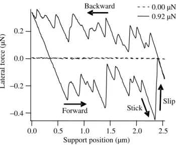
A typical measurement of the lateral forces between the round slider and the countersurface is given in Fig. 2, presented as a ‘friction loop’. We have observed repeatable, irregular stick–slip motion, and wear at high normal loads [33]. The en-ergy dissipated by the friction is given by the area enclosed by the loop. The static friction coefficient µsis the ratio of lateral force to normal force at the moment the device starts slipping, while the dynamic friction coefficient µdis undetermined be-cause the slider moves in a stick–slip fashion. Arguably, there is no good measure
Figure 2. Typical friction loop measured with the tribometer.
for µs in this particular measurement either, because in the stick–slip motion, the first slip is not at the highest lateral force encountered in the loop. We, therefore, define µsas the highest lateral force encountered, a measure that is prone to statis-tical errors. In this particular device under the conditions of temperature= 24.4◦C and relative humidity= 24%, µs= 0.45, and the average friction µav= 0.21. The tribometer makes one forward and backward sliding cycle per 0.5 seconds in this experiment. The slips are the moments at which energy is being dissipated: the potential energy stored in the stuck device under tension is converted to the kinetic energy of the slip, which is converted to phonons that are launched into the structure at the moment of impact.
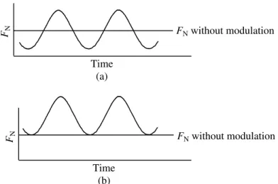
To investigate the effect of vibrations on the friction encountered, we have sys-tematically varied the normal force by modulating it at different frequencies and amplitudes. Two basic sets of data have been acquired: one in which the average normal load is kept constant (50 nN), and one in which the minimum normal load is kept constant (also 50 nN) (Fig. 3). Note that the actual normal force on the surfaces is marginally higher than the applied normal load due to adhesion between the sur-faces. The sliding distance was 1.2 µm back and forth, and one loop was acquired in 0.5 s. All the different modulation conditions have been summarized in Table 1.
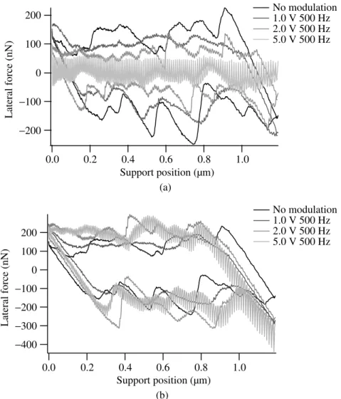
Typical results for both types of modulation are given in Fig. 4. At low modu-lation voltage amplitudes, no effect is seen. Only when a significant modumodu-lation is applied, the effect becomes noticeable, as a reduction of the area of the friction loop (less energy dissipation means less friction). Figure 5 shows the effect of the mod-ulation amplitude on the friction, with an actuation frequency of 500 Hz. At 5 Vpp modulation, with the average normal load kept constant, the friction reduction is so large that the friction basically drops to zero! We associate this regime with the
Figure 3. Two modulation types have been employed: (a) average normal load constant, and (b)
min-imum normal load constant.
Table 1.
Measurement conditions
Amplitude (Vpp) Frequency (Hz) Type of modulation
0.01 (0.56 nNpp) 20 Constant average normal load
0.1 (5.6 nNpp) 50 Constant minimal normal load
0.2 (11.2 nNpp) 100
0.5 (28 nNpp) 500
1.0 (56 nNpp) 2.0 (112 nNpp) 5.0 (280 nNpp)
There were 56 different settings in total, subscript pp means peak-to-peak. Both the driving ampli-tude for the vibrations in Volt, and the calculated resultant variation in normal load (in parentheses) are given.
situation in which the contact between the surfaces is temporarily broken and re-formed at every modulation cycle. We also see that the friction remains constant in the case where the minimum normal load is kept constant, even though the average normal load is increasing significantly with increasing modulation. This means that the surfaces can slip during the lowest force part of the modulation cycle.
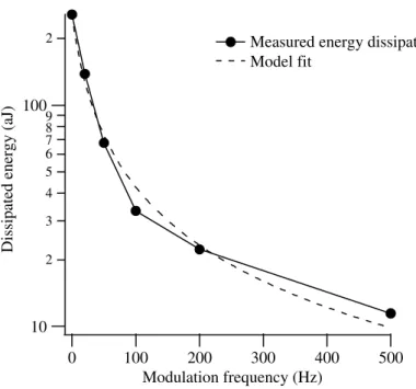
Important also is the behaviour as a function of modulation frequency. To obtain low friction, the modulation frequency should be much higher than the frequency of the original stick–slip process. Only then the energy-dissipating slip events are successfully suppressed. We see this in Fig. 6. The figure shows the friction loops as a function of frequency. Only at high modulation frequencies, the surfaces lose contact often enough to prevent stick–slip behaviour. Figure 7 shows the energy
Figure 4. Results of normal force modulation in the case (a) where the average normal load is kept
constant, and (b) where the minimum normal load is kept constant. All curves are 300 sliding cycle averages to average out the noise in the measurements.
dissipation as a function of frequency. The energy dissipation drops steadily with increasing modulation frequency and is not quite zero even at 500 Hz.
4. Discussion
As in the macroscopic and the atomic scale cases, we have found that on the scale of MEMS, modulation of the normal force can significantly reduce the friction ex-perienced by the sliding contact. Important to notice is that the physical processes governing the friction reduction on the macroscopic and the atomic scales are
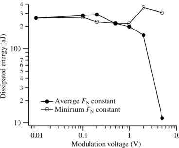
com-Figure 5. At high modulation amplitude, the energy dissipation, and hence the friction, drops sharply.
The energy dissipation has been calculated by determining the full area of the loop.
Figure 6. The effect of modulation frequency on the friction loop when the average normal load is
constant at 5.0 Vppmodulation amplitude. Only at high modulation frequencies, the system vibrates fast enough to go from stick–slip behaviour to smooth sliding.
pletely different: on the macroscopic scale, it is the (intermittent) full loss of contact, while on the atomic scale, super-slipperiness has been observed even if the surfaces are fully in contact, albeit with strong periodic reduction in normal force.
That we are not dealing with the atomic scale case in our experiment is already obvious from the amplitude of the modulation that we have to apply to observe the
Figure 7. The energy dissipation as a function of modulation frequency for the case that the average
normal force is kept constant at 5 Vppmodulation.
friction reduction. At 500 Hz and 5 Vpp modulation (the typical case for full loss of friction), there is a significant pulling force on the contact. After the adhesion is subtracted (measured separately as discussed in [32], being with these samples under these conditions only a few nN), we end up with a relatively high net force trying to separate the two surfaces. The pulling force at 5 Vppmodulation is 90 nN at the minimum of the modulation period. At 2 Vpp the pulling force is 16 nN on the surfaces at the lowest point of the modulation cycle, but in that case significant friction is still observed, even though the pulling force is already larger than the static adhesion. Based on the applied forces alone, at 2 Vpp, loss of contact would be expected during 15% of the cycle, while for 5 Vpp, this is 38%.
We certainly do not have a contact with a net pressure of the surfaces towards each other when the friction vanishes, like in the atomic-scale case of Socoliuc et
al.[28]. Instead, it may be that the dynamic breaking of the capillary neck of the condensed water is observed, which is always present at typical relative humidi-ties between hydrophilic surfaces [35–37] and that this makes up the largest part of the dynamic adhesion force between them. This would mean that the surfaces are effectively in contact for a much longer time than anticipated based on the mod-ulation amplitude and the measured adhesion force alone. The physical principle will be investigated later and it is expected that it is related to the work reported by Gao et al. [38], Gourdon and Israelachvili [39], and Jinesh et al. [40] on the
tempo-ral behaviour of confined, ordered liquid layers between contacting surfaces on the nanometer scale. Other MEMS related work in this area is given in [41–43].
The friction reduction effect only occurs if the modulation lowers the normal force during part of the cycle. From Fig. 5 it is seen that there is a critical amplitude of the normal force modulation below which there is only partial cancellation of the friction force, and from Fig. 7 it is learned that the frequency is also an important parameter.
The dependence of the dissipated energy on modulation frequency can be ratio-nalized with a simple model, which nicely reproduces the general features of the observations. If one assumes that slip will always occur as soon as the lateral force exceeds the static friction coefficient µs times the normal force FN, and that the slip will make the lateral force go to zero, the average friction force FF,avis half the maximum static friction force:
FF,av=12µsFN. (1)
If l is the sliding distance, the corresponding dissipated energy E is E= lFF,av=1
2lµsFN. (2)
When one starts pulling, the ‘reference position’ is moved. This is the position where the slider would have been if there would have been no contact, and to which it is connected by the springs with spring coefficient kspringto the rest of the MEMS tribometer. If the reference position moves by x, before the first slip event occurs, the lateral force FLon the stuck contact increases as
FL= xkspring. (3)
FLreaches its maximum when it reaches µsFNat position x0, after which it starts its first slip, so its first slip occurs at
x0= µsFN
kspring. (4)
If the expected number of stick–slip events n during the sliding over the distance l is much larger than unity, it is given by
n= l x0 =
kspring
µsFNl, (5)
being the average number of times that the friction force reaches its maximum value, after which the contact slips and the friction falls back to zero. When FNis modulated, sliding will occur every cycle at the point where the momentary value of µsFNfalls below FF. If FNgoes to zero, as in the case of loss of contact, sliding will certainly occur at every modulation cycle. The number of slip events n hence will be increased, resulting in a lower FF,av. It is estimated that this increase in the
number of slips will simply be equal to the number of times that the modulated nor-mal force is mininor-mal (over the distance l), which is lf /v, where f is the modulation frequency and v the sliding velocity, so that l/v is the time required to traverse the distance l. The factor R by which the average friction force is reduced can now be estimated as the ratio between the original number of stick–slip cycles in the un-modulated case, described in equation (5), and the increased number of stick–slip events in the modulated case.
R= (kspring/(µsFN))l f l/v+ (kspring/(µsFN))l = 1 1+ f µsFN/(vkspring) (6) and E=1 2RlµsFN. (7)
We find that the ratio, and hence the dissipated energy according to equations (2) and (7), has an approximately 1/(f + constant) behaviour, and the fit based on this relationship has been plotted in Fig. 7 along with the data. The stochastic nature of the stick–slip behaviour in the MEMS device has been neglected, as well as the relative phase of the original stick–slip events and the modulation. Also the possibility of sliding before the modulation reaches its minimum and the fact that less ‘natural’ slip events will occur when the force build-up is frustrated as the modulation frequency increases have not been taken into account, but the agreement is already excellent.
The implementation of the friction control method described in this experiment can follow different routes. Electrostatically induced vibrations are convenient, but will certainly not be applicable to all MEMS-based devices. Other actuation schemes can be envisioned as well, e.g., the actuation of the whole die by a small piezo-transducer.
The effect of normal force modulation on the wear rate of a MEMS device with sliding surfaces remains to be investigated, and will certainly be material-dependent. The highest normal force encountered between the surfaces will in most cases be higher than without actuation, which may crush the highest contact as-perities even further than they would normally be. On the other hand, the surfaces are only stressed under impact, not anymore under shear, while shear often creates more damage. It may be easier to optimize coatings for MEMS devices for impact resistance than shear resistance. The effect of normal force modulation on wear should certainly be studied in future work.
5. Conclusions
We have shown that friction between MEMS surfaces can be reduced significantly by applying a modulation of the normal force, in which the average normal force remains constant, but the actual value is fluctuating. The minimum modulation fre-quency to obtain super-slipperiness is related to the frefre-quency of the stick–slip
events in the system and for full friction reduction the modulation frequency should be chosen significantly higher than the highest natural frequency of slip events. Similarly, the amplitude of the modulation should be so high as to enforce periodic loss of contact between the surfaces, although only a short contact time is required every cycle. The effect of the modulation frequency on the friction reduction is described well by a simple model.
By optimizing the frequency and amplitude of the modulation, the friction can be reduced to a very low value that will in most MEMS devices not cause any friction-related seizure of sliding components (lateral stiction).
Acknowledgements
This work was financially supported by the Dutch NWO-STW foundation in the ‘Veni’ program under ref no. LMF.7302. The third author would also like to thank the French Foreign Affairs Ministry for a Lavoisier fellowship and the Dutch FOM foundation for financial support.
References
1. K. Deng, G. P. Ramanathan and M. Mehregany, J. Micromech. Microeng. 4, 226 (1994). 2. U. Srinivasan, M. R. Houston, R. T. Howe and R. Maboudian, J. Microelectromech. Syst. 7, 252
(1998).
3. X. Y. Zhu and J. E. Houston, Tribology Lett. 7, 87 (1999).
4. W. R. Ashurst, C. Yau, C. Carraro, R. Maboudian and M. T. Dugger, Sensors Actuators A 91, 239 (2001).
5. W. R. Ashurst, C. Yau, C. Carraro, R. Maboudian and M. T. Dugger, J. Microelectromech. Syst.
10, 41 (2001).
6. R. Maboudian, W. R. Ashurst and C. Carraro, Sensors Actuators A 82, 219 (2000). 7. S. T. Patton, W. D. Cowan, K. C. Eapen and J. S. Zabinski, Tribology Lett. 9, 199 (2000). 8. D. A. Hook, S. J. Timpe, M. T. Dugger and J. Krim, J. Appl. Phys. 104, 034303 (2008). 9. R. Bandorf, H. Lüthje and T. Staedler, Diamond Relat. Mater. 13, 1491 (2004). 10. S. Sundararajan and B. Bhushan, Wear 217, 251 (1998).
11. G. Fleming, S. S. Mani, J. J. Sniegowski and R. S. Blewer, US patent 6,290,859 (2001). 12. H. D. Fridman and P. Levesque, J. Appl. Phys. 30, 1572 (1959).
13. D. M. Tolstoi, Wear 10, 199 (1967). 14. W. Lenkiewicz, Wear 13, 99 (1969).
15. B. Armstrong-Hélouvry, P. Dupomt and C. C. De Wit, Automatica 30, 1083 (1994).
16. C. M. Mate, G. M. McClelland, R. Erlandsson and S. Chiang, Phys. Rev. Lett. 59, 1942 (1987). 17. L. Prandtl, Z. Angew. Math. Mech. 8, 6 (1928).
18. G. A. Tomlinson, Phil. Mag. 7, 905 (1929).
19. W. Zhong and D. Tománek, Phys. Rev. Lett. 64, 3054 (1990).
20. D. Tománek, W. Zhong and H. Thomas, Europhys. Lett. 15, 887 (1991). 21. R. Feynman, J. Microelectromech. Syst. 2, 4 (1993).
22. E. Gnecco, R. Bennewitz, T. Gyalog, Ch. Loppacher, M. Bammerlin, E. Meyer and H.-J. Gün-therodt, Phys. Rev. Lett. 84, 1172 (2000).
23. Y. Sang, M. Dubé and M. Grant, Phys. Rev. Lett. 87, 174301 (2001).
24. K. B. Jinseh, S. Y. Krylov, H. Valk, M. Dienwiebel and J. W. M. Frenken, Phys. Rev. B 78, 155440 (2008).
25. S. Y. Krylov, K. B. Jinesh, H. Valk, M. Dienwiebel and J. W. M. Frenken, Phys. Rev. E 71, 065101 (2005).
26. F. Dinelli, S. K. Biswas, G. A. D. Briggs and O. V. Kosolov, Appl. Phys. Lett. 71, 1177 (1997). 27. S. Jeon, T. Thundat and Y. Braiman, Appl. Phys. Lett. 88, 214102 (2006).
28. A. Socoliuc, E. Gnecco, S. Maier, O. Pfeiffer, A. Baratoff, R. Bennewitz and E. Meyer, Science
313, 207 (2006).
29. See www.memscap.com/en_mumps.html
30. D. C. Senft and M. T. Dugger, Proc. SPIE 3224, 31 (1997).
31. N. R. Tas, C. Gui and M. Elwenspoek, J. Adhesion Sci. Technol. 17, 547 (2003). 32. W. M. van Spengen and J. W. M. Frenken, Tribology Lett. 28, 149 (2007).
33. W. M. van Spengen, E. Bakker and J. W. M. Frenken, J. Micromech. Microeng. 17, S91 (2007). 34. W. M. van Spengen and T. H. Oosterkamp, J. Micromech. Microeng. 17, 828 (2007).
35. R. Maboudian and R. T. Howe, J. Vac. Sci. Technol. B 15, 1 (1997).
36. W. M. van Spengen, R. Puers and I. De Wolf, J. Micromech. Microeng. 12, 702 (2002). 37. M. P. De Boer, Expl. Mech. 47, 171 (2007).
38. J. Gao, W. D. Luedtke and U. Landman, J. Phys. Chem. B 102, 5033 (1998). 39. D. Gourdon and J. Israelachvili, Phys. Rev. E 68, 021602 (2003).
40. K. B. Jinesh and J. W. M. Frenken, Phys. Rev. Lett. 96, 166103 (2006). 41. Z. Wei and Y.-P. Zhao, Chin. Phys. 13, 1320 (2004).
42. K. Komvopoulos, J. Adhesion Sci. Technol. 17, 477 (2003).