HAL Id: tel-02966675
https://tel.archives-ouvertes.fr/tel-02966675
Submitted on 14 Oct 2020
HAL is a multi-disciplinary open access
archive for the deposit and dissemination of sci-entific research documents, whether they are pub-lished or not. The documents may come from teaching and research institutions in France or abroad, or from public or private research centers.
L’archive ouverte pluridisciplinaire HAL, est destinée au dépôt et à la diffusion de documents scientifiques de niveau recherche, publiés ou non, émanant des établissements d’enseignement et de recherche français ou étrangers, des laboratoires publics ou privés.
Corrosion properties of 17-4 PH martensitic stainless
steel obtained by additive manufacturing
Michella Alnajjar
To cite this version:
Michella Alnajjar. Corrosion properties of 17-4 PH martensitic stainless steel obtained by additive manufacturing. Other. Université de Lyon, 2019. English. �NNT : 2019LYSEM035�. �tel-02966675�
N°d’ordre NNT : 2019LYSEM035
THESE de DOCTORAT DE L’UNIVERSITE DE LYON
opérée au sein de
Mines Saint-Etienne
Ecole Doctorale
N° 488
Sciences, Ingénierie, Santé
Spécialité de doctorat
:Sciences et Génie des Matériaux
Soutenue publiquement le 18/12/2019, par :
Michella ALNAJJAR
Corrosion properties of 17-4 PH
martensitic stainless steel obtained by
additive manufacturing
Devant le jury composé de :
Delagnes, Denis Professeur IMT Mines Albi Président
Duhamel, Cécilie Professeur Mines ParisTech Rapporteure
Blanc, Christine Professeur Toulouse INP-ENSIACET Rapporteure
Delagnes, Denis Professeur IMT Mines Albi Examinateur
Christien, Frédéric Professeur Mines Saint-Etienne Directeur de thèse
Wolski, Krzysztof Directeur de recherche Mines Saint-Etienne Co-directeur de thèse
Bosch, Cédric Chargé de recherche Mines Saint-Etienne Co-encadrant
Spécialités doctorales Responsables : Spécialités doctorales Responsables
SCIENCES ET GENIE DES MATERIAUX K. Wolski Directeur de recherche MATHEMATIQUES APPLIQUEES O. Rous tan t, Maîtr e- as s is tan t MECANIQUE ET INGENIERIE S. Drapier, professeur INFORMATIQUE O. Boissier, Professeur GENIE DES PROCEDES F. Gruy , Maître de recherche SCIENCES DES IMAGES ET DES FORMES JC. Pinoli, Professeur SCIENCES DE LA TERRE B. Guy , Directeur de recherche GENIE INDUSTRIEL N. Absi, Maitr e de rech er ch e SCIENCES ET GENIE DE L’ENVIRONNEMENT D. Graillot, Directeur de recherche MICROELECTRONIQUE Ph. Lalevée, Professeur
EMSE : Ense ignants-chercheurs et chercheurs autorisés à diriger des thèses de doctorat (titulaires d’un doctorat d’État ou d’une HDR)
ABSI Nabil MR Génie industriel CMP AUGUSTO Vincent CR Im age, Vision, Signal CIS AVRIL Stéphane PR2 Mécanique et ingénierie CIS BA DEL Pierre MA (M DC) Mécanique et ingénierie CIS BALBO Flavien PR2 Inform atique FAYOL BASSEREAU Jean-François PR Sciences et génie des m atériaux SMS BATTON-HUBERT Mireille PR2 Sciences et génie de l'environnem ent FAYOL
BEIGBEDER Michel MA (M DC) Inform atique FAYOL BLAYAC Sy lvain MA (M DC) Microélectronique CMP BOISSIER Olivier PR1 Inform atique FAYOL BONNEFOY Olivier PR Génie des Procédés SPIN
BO RBE LY Andras MR(DR2) Sciences et génie des m atériaux SMS BOUCHER Xavier PR2 Génie Industriel FAYOL BRODHAG Christian DR Sciences et génie de l'environnem ent FAYOL BRUCHON Julien MA (M DC) Mécanique et ingénierie SMS CAMEIRAO Ana MA (M DC) Génie des Procédés SPIN CHRISTIEN Frédéric PR Science et génie des matériaux SMS DAUZERE-PERES Stéphane PR1 Génie Industriel CMP DEBAYLE Johan MR Sciences des Im ages et des Formes SPIN DEGEORGE Jean-Michel MA (M DC) Génie industriel Fay ol DEL A FOSSE David PR0 Sciences et génie des m atériaux SMS
DELORME Xavier MA (M DC) Génie industriel FAYOL DESRAYAUD Christophe PR1 Mécanique et ingénierie SMS
DJENIZIAN Thierry PR Science et génie des matériaux CMP BERGER-DOUCE Sandrine PR1 Sciences de gestion FAYOL
DRAPIER Sy lvain PR1 Mécanique et ingénierie SMS DUTERTRE Jean-Max MA (M DC) CMP EL MRABET Nadia MA (M DC) CMP FA UCHE U Jenny MA (M DC) Sciences et génie des m atériaux SMS FAVERGEON Loïc CR Génie des Procédés SPIN
FEILLET Dom inique PR1 Génie Industriel CMP FOREST Valérie MA (M DC) Génie des Procédés CIS FRACZKIEWICZ Anna DR Sciences et génie des m atériaux SMS GARCIA Daniel MR(DR2) Sciences de la Terre SPIN
GAVET Yann MA (M DC) Sciences des Im ages et des Form es SPIN GERINGER Jean MA (M DC) Sciences et génie des m atériaux CIS GOEURIOT Dom inique DR Sciences et génie des m atériaux SMS GONDRAN Natacha MA (M DC) Sciences et génie de l'environnem ent FAYOL GON Z A L E Z FELI U Jesus MA (M DC) Sciences économ iques FAYOL GRAILLO T Didier DR Sciences et génie de l'environnem ent SPIN GROSSEAU Philippe DR Génie des Procédés SPIN GRU Y Frédéric PR1 Génie des Procédés SPIN H A N Woo-Suck MR Mécanique et ingénierie SMS HERRI Jean Mich el PR1 Génie des Procédés SPIN KERM O U CH E Guillaum e PR2 Mécanique et Ingénierie SMS
KLOCKER Helm ut DR Sciences et génie des m atériaux SMS LAFOREST Valérie MR(DR2) Sciences et génie de l'environnem ent FAYOL
LERICHE Rodolphe CR Mécanique et ingénierie FAYOL MALLIARAS Georges PR1 Microélectronique CMP MOL IM ARD Jérôm e PR2 Mécanique et ingénierie CIS M O UTTE Jacques CR Génie des Procédés SPIN NAVARRO Laurent CR CIS
NEUBERT Gilles FAYOL
NIKOLOVSKI Jean-Pierre Ingénieur de recherche Mécanique et ingénierie CMP NORTIER Patrice PR1 Génie des Procédés SPIN O CON N O R Rodney Philip MA (M DC) Microélectronique CMP PICA RD Gauthier MA (M DC) Inform atique FAYOL
PINOLI Jean Charle s PR0 Sciences des Im ages et des Formes SPIN POURCHEZ Jérém y MR Génie des Procédés CIS
ROUSSY Agnès MA (M DC) Microélectronique CMP ROUSTANT Olivier MA (M DC) Mathém atiques appliquées FAYOL
SAN AU R Sébastien MA (M DC) Microélectronique CMP SERRIS Eric IRD FAYOL STOLARZ Jacques CR Sciences et génie des m atériaux SMS
TRIA Assia Ingénieur de recherche Microélectronique CMP VALDIVIESO François PR2 Sciences et génie des m atériaux SMS VIRICELLE Jean Paul DR Génie des Procédés SPIN
WOLSKI Krzy stof DR Sciences et génie des m atériaux SMS XIE Xiaolan PR0 Génie industriel CIS YUGMA Gallian CR Génie industriel CMP
M ise à jo ur : 30 /08 /2018
3
Table of contents
General introduction ...7
Chapter 1 Literature review... 13
Table of contents ... 15
1.1 Additive manufacturing ... 17
1.2 Selective laser melting ... 18
1.2.1 Microstructures of SLM-ed materials ... 22
1.3 17-4 PH stainless steel ... 24
1.3.1 Wrought 17-4 PH stainless steel... 24
1.3.2 SLM-ed 17-4 PH steel ... 26
1.4 Corrosion of stainless steels ... 27
1.4.1 General corrosion ... 29
1.4.2 Pitting corrosion ... 29
1.4.3 Corrosion measurement techniques... 30
1.4.3.1 Open circuit potential (OCP) ... 30
1.4.3.2 Potentiodynamic polarization ... 31
1.4.4 Corrosion of SLM-ed stainless steels... 32
1.4.5 Corrosion of wrought 17-4 PH steel... 33
1.4.6 Corrosion of SLM-ed 17-4 PH steel ... 33
1.5 Hydrogen embrittlement ... 34
1.5.1 Hydrogen-metal interaction ... 34
1.5.1.1 Hydrogen adsorption and absorption ... 34
1.5.1.2 Hydrogen diffusion... 35
1.5.1.2.1 Lattice diffusion... 35
1.5.1.2.2 Short-circuit diffusion ... 35
1.5.1.2.3 Hydrogen transport by moving dislocations ... 36
1.5.1.3 Hydrogen trapping ... 36
1.5.2 HE mechanisms ... 36
1.5.3 HE of ferritic steels... 37
1.5.4 HE of martensitic steels ... 37
1.5.5 Effect of strain rate on HE... 38
1.5.6 Effect of yield strength on HE... 39
4
1.6 References ... 42
Chapter 2 Evidence of austenite by-passing in a stainless steel obtained from laser melting additive manufacturing ... 49
Table of contents ... 51
2.1 Abstract ... 53
2.2 Introduction ... 53
2.3 Experimental procedure ... 54
2.4 Results and discussion ... 56
2.4.1 Microstructure of wrought 17-4 PH steel ... 56
2.4.2 Phase identification in as-built 17-4 PH steel ... 57
2.4.3 Microstructure of as-built 17-4 PH steel ... 58
2.4.4 Microstructure of as-built 17-4 PH after re-austenitization heat treatment ... 65
2.4.5 Dilatometric measurements ... 66
2.5 Conclusion ... 68
2.6 References ... 69
Chapter 3 Influence of microstructure and manganese sulfides on corrosion resistance of selective laser melted 17-4 PH stainless steel in acidic chloride medium ... 73
Table of contents ... 75 3.1 Abstract ... 77 3.2 Introduction ... 77 3.3 Experimental procedure ... 79 3.3.1 Materials ... 79 3.3.2 Microstructural characterization ... 80 3.3.3 Electrochemical measurements ... 81
3.4 Results and discussion ... 82
3.4.1 Microstructure ... 82
3.4.2 Potentiodynamic measurements ... 87
3.4.3 Open circuit potential ... 90
3.4.4 XPS measurements ... 92
3.5 Conclusion ... 94
5 Chapter 4 A comparative study of hydrogen embrittlement of selective laser melted and wrought
17-4 PH stainless steel ... 101 Table of contents ... 103 4.1 Abstract ... 105 4.2 Introduction ... 105 4.3 Experimental procedures ... 107 4.3.1 Material ... 107 4.3.2 Microstructural characterization ... 107
4.3.3 Tensile tests in air ... 108
4.3.4 Tensile tests under cathodic charging ... 108
4.3.5 Electrochemical permeation test ... 108
4.4 Results and discussion ... 109
4.4.1 Microstructural analysis ... 109
4.4.2 Tensile properties in air... 110
4.4.3 Hydrogen permeation behavior ... 114
4.4.4 Tensile tests under hydrogen charging ... 115
4.5 Conclusion ... 121
4.6 References ... 123
General conclusions and perspectives... 127
Acknowledgments... 133
Appendixes... 135
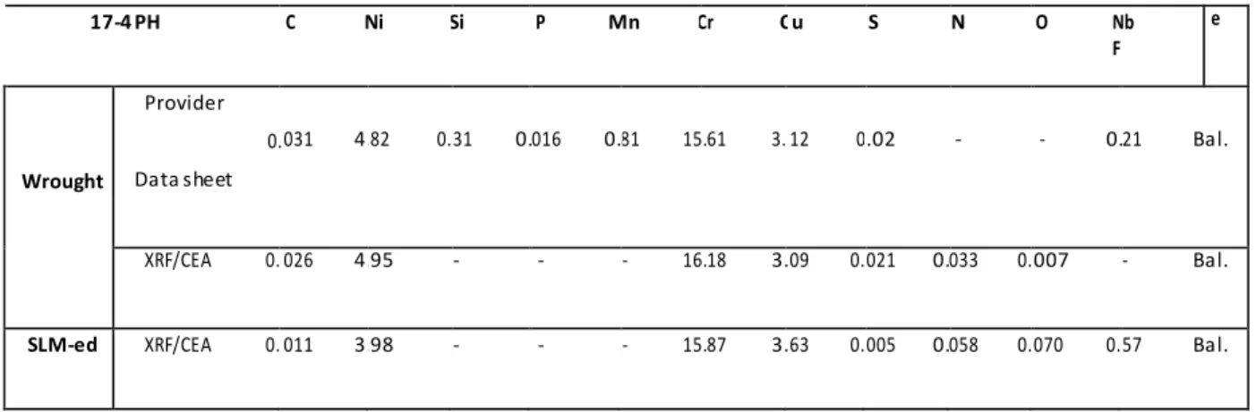
Appendix 1: List of the materials used in this thesis ... 137
Appendix 2: Neutron diffraction study of phase transformations in steel 17-4PH... 138
Appendix 3: EBSD analysis of a 17-4 PH gas-atomized powder ... 141
Appendix 4: Conventional and real strain rates during tensile testing ... 144
The main objective of this thesis was to study the corrosion behavior of 17-4 PH stainless stee l fabricated by selective laser melting (SLM). It was conducted in the SMS Materials and mechani cal engineering R&D center (LGF laboratory) of Mines Saint-Etienne (France).
This work was motivated by the growing demand of additively manufactured materials, specifically of selective laser melted alloys. Additive manufacturing is a relatively new technology that allows 3D objects to be fabricated layer by layer according to a computer-aided design (CAD). SLM is a techni que of additive manufacturing, which utilizes high power laser to melt metallic powder to produce 3D objects. SLM is still in its development period and there are still many limitations for this technology, including the availability and price of powders, the limited choice of materials, sanitary issues and problems in the recyclability of powders. In addition, another very important issue is the durability of the SLM-ed materials in service conditions, which is still unclear and not fully explored. The durabil ity of SLM-ed steels was our point of interest is in this PhD study.
After defining the context of this thesis, the choice of the material had to be done, which depe nde d on the availability of the powder and the ease of fabrication by SLM technique. The 17-4 PH stainle ss steel was selected for this study, because it responded to those criteria. In addition, it is one of the most used materials in the SLM fabrication and thus it was easy to find industrial partners able to produce SLM-ed 17-4 PH steel with optimized process parameters. Thus, the durability study was conducted on SLM-ed 17-4 PH steels having limited porosity and appropriate mechanical properti es compared to its wrought counterpart. What motivated our study is also the limited research on thi s SLM-ed steel so far, in particular concerning its durability.
The durability is a very wide and complex subject, but obviously, due to the limited time of the PhD, we had to choose specific types of conditions and environments. Our first choice was to investigate the electrochemical corrosion because it is the most encountered type of corrosion during service of stainless steels, including 17-4 PH steel. The electrochemical characterization was done in a typi cal acidic medium containing 30 g/l NaCl, which is close to the seawater concentration and already use d a lot in corrosion research. Our second choice was to study the hydrogen embrittlement (HE), that i s a crucial problem to address since hydrogen is likely to enter the material as soon as corrosion reacti ons occur at the surface during service. In addition, high strength steels as the one studied he re are expected to be sensitive to hydrogen embrittlement. We thought it would be interesting to investigate how a high strength material produced using SLM would be affected by HE.
It was a deliberate choice in this study to work in a comparative manner: the different seri es of experiments were always conducted on both the SLM-ed material and the conventional wrought
material. Several SLM-ed materials were studied; they were obtained from different industrial partners. A list of the different materials, including SLM-ed and wrought, is provided in Appendix 1. This thesis is divided into four main chapters. The first chapter is the literature review and the thre e following chapters present the work done during this PhD thesis.
The first chapter presents a review on additive manufacturing with particular interest on selective lase r melting (SLM) process and the microstructures obtained by SLM. This was followed by a literature review on the microstructure of wrought and SLM-ed 17-4 PH steels. The corrosion of stainless steel s and some corrosion measurements techniques were then discussed. A literature review on the corrosion of SLM-ed stainless steels, wrought and SLM-ed 17-4 PH steels were presented. A presentation on hydrogen embrittlement (HE) was given, which included hydrogen-metal interaction, hydrogen diffusion and trapping and HE mechanisms. A literature review on HE of ferritic and martensitic steels, the effect of strain rate and yield strength on HE and subcritical crack growth was conducted.
The second chapter of this thesis is dedicated to the study of the microstructure of SLM-ed 17-4 PH steel in the as-built state. It was expected that the resulted microstructure would be different from i ts wrought counterpart, due to the high thermal rates and the complex thermal history experienced during SLM. Optical microscopy, X-ray diffraction, scanning electron microscopy equipped with electron backscatter diffraction and energy-dispersive X-ray spectroscopy were all used in this study. In addition, a comparison of microstructures was made between wrought and SLM-ed steel s. A detailed analysis was conducted to fully understand this unique SLM-ed microstructure. Dilatometry measurements were done in order to identify the phase transformations in this steel at high temperatures. Furthermore, microstructures of 17-4 PH steels obtained by different SLM machi ne s were also observed in order to generalize and ensure reproducibility of the results. As shown in thi s chapter the microstructures obtained in the as-built state are very unique and different from the conventional martensitic microstructure of the wrought 17-4 PH steel. One approach could have be e n to heat treat the SLM-ed material to make it "as similar as possible" to the wrought material. This i s not the approach we followed. In contrast, we thought that the unique microstructure obtained from SLM was very interesting from the academic point of view. This is the reason why the corrosion studi es presented in the following chapters were conducted on the SLM-ed steel without any treatment likely to recover the usual microstructure of 17-4 PH steel.
The third chapter of this thesis focused on the corrosion properties of the SLM-ed 17-4 PH stee l , specifically the electrochemical behavior. First, the microstructures of wrought steel and two SLM-e d
their inclusion, and their porosity contents. Secondly, anodic scans were performed on all thre e materials in acidic chloride containing environment. As the corrosion behavior is directly related to the microstructure, it was very important to correlate the electrochemical results with the observe d microstructures. Furthermore, X-ray photoelectron spectroscopy was used to confirm the correlati on between surface composition and corrosion behavior.
The fourth chapter of this thesis continue the investigation of the corrosion properties of the SLM-e d 17-4 PH steel, specifically the hydrogen embrittlement. The materials studied were both wrought and SLM-ed steels that were subjected to an overaging treatment at 580°C for 4 hours. As usual, the i r microstructures were first reviewed. This was followed by tensile testing in air for smooth and notched specimens. Slow strain rate tests (SSRT) were then performed under cathodic charging in aci di c chloride solution. Comparisons were made between the stress-strain curves in air and under hydroge n charging for both wrought and SLM-ed steels, in order to evaluate the degree of hydrogen susceptibility for each steel. The effect of strain rate and pre-charging on hydrogen susceptibility were also investigated. The fracture surfaces were observed after each test. Moreover, electrochemical permeation tests were conducted to reveal the hydrogen diffusion distance during SSRT. The analysi s consisted of correlating the SSRT results and the observed fractographs to the charging conditions and the microstructures. The hydrogen embrittlement mechanisms of each material were also discussed, in a comparative way.
The three main chapters of this manuscript are presented as self-consistent papers. Each of the m contains a short literature review, in addition to the general literature review presented at the beginning of the manuscript.
Table of contents
1.1 Additive manufacturing ... 17
1.2 Selective laser melting ... 18
1.2.1 Microstructures of SLM-ed materials ... 22
1.3 17-4 PH stainless steel ... 24
1.3.1 Wrought 17-4 PH stainless steel... 24
1.3.2 SLM-ed 17-4 PH steel ... 26
1.4 Corrosion of stainless steels ... 27
1.4.1 General corrosion ... 29
1.4.2 Pitting corrosion ... 29
1.4.3 Corrosion measurement techniques... 30
1.4.3.1 Open circuit potential (OCP) ... 30
1.4.3.2 Potentiodynamic polarization ... 31
1.4.4 Corrosion of SLM-ed stainless steels... 32
1.4.5 Corrosion of wrought 17-4 PH steel... 33
1.4.6 Corrosion of SLM-ed 17-4 PH steel ... 33
1.5 Hydrogen embrittlement ... 34
1.5.1 Hydrogen-metal interaction ... 34
1.5.1.1 Hydrogen adsorption and absorption ... 34
1.5.1.2 Hydrogen diffusion... 35
1.5.1.2.1 Lattice diffusion... 35
1.5.1.2.2 Short-circuit diffusion ... 35
1.5.1.2.3 Hydrogen transport by moving dislocations ... 36
1.5.1.3 Hydrogen trapping ... 36
1.5.2 HE mechanisms ... 36
1.5.3 HE of ferritic steels... 37
1.5.4 HE of martensitic steels ... 37
1.5.5 Effect of strain rate on HE... 38
1.5.7 Subcritical crack growth ...40 1.6 References ...42
1.1 Additive manufacturing
Additive manufacturing (AM) also known as 3D-printing refers to the technologies that builds a thre e - dimensional object by adding material layer by layer according to computer-aided design (CAD) model . As opposed to traditional “subtractive” fabrication methods where the finished part is obtained by removing material from a block part by cutting and/or drilling, AM requires almost no tooling in orde r to produce a functioning part. This technique is capable of building parts having very complex geometries that usually are difficult or sometimes impossible to be fabricated by conventional manufacturing processes [1–4]. In addition, AM presents a lot of potential benefits such as reduci ng the fabrication time and making economies in material by minimizing the waste. Thus, due to i ts various advantages, AM has been developing and growing rapidly in the past few years. By 2016, the global 3D printing market reached nearly US$ 3.7 billion and is expected to grow at a compound annual growth rate of 23% for the period of 2016-2021 [5].
This technology was first introduced in the late 1980 as rapid prototyping solution and was l ate r evolved to rapid tooling and manufacturing. In the early stages, AM was used for rapid prototyping such as building prototype parts for testing and assessment, fabricating models for art and medi cal uses and casting patterns. As development and improvement of AM technology continued to grow, indirect and direct tooling emerged as a new method of fabrication of tools, molds and dies [6]. More recently, AM has been adopted for building near-net shape and end-use products [2,3]. Its application has broadened to include biomedical industries, aerospace, civil engineering, automobile and e ve n fashion industries [3,7]. A wide range of materials can be used in AM including plastics, polymers, metals, concrete, ceramics and human tissue. Depending on the state of the material used, AM can be divided into 3 main groups: liquid based such as fuse deposition modelling, solid based such as laminated object manufacturing and powder based such as selective laser sintering [8]. AM incorporates different processes that can be classified into seven different categories [1,9]:
1- Binder jetting (BJ) where a liquid binding agent is printed into thin layer of powder particles to join them together. An example of BJ process is 3D inkjet technology.
2- Directed energy deposition (DED) where focused thermal energy melts materials during deposition. Examples of this process are laser engineered net shaping and 3D laser cladding. 3- Material extrusion (ME) where material is pushed out through a nozzle and deposited layer by
layer. The most common example of ME is fuse deposition modelling.
4- Material jetting (MJ) where material is jetted from a nozzle on the build platform using continuous or drop on demand method.
5- Powder bed fusion (PBF) where a laser or electron beam source selectively fuses a powde r layer deposited on the build platform. Examples of PBF are electron beam melting (EBM) and selective laser sintering (SLS) or melting (SLM).
6- Sheet lamination (SL) where sheets or ribbons of material are bonded together. Examples of this process are ultrasonic additive manufacturing and laminated object manufacturing. 7- Vat photopolymerization (VP) where liquid polymer in a vat is light-cured.
AM is still an evolving technology and many researches are being done in order to improve the profitability and the quality of produced materials. However, there are still some limitations for thi s technology, which includes poor surface quality due to “stair-stepping” effect, the limited number of materials that can be used, poor repeatability and powder availability [3,10]. In addition, the microstructures obtained are usually different from their wrought counterparts. Thus, their mechanical and corrosion properties need to be thoroughly examined before their use in service [11].
1.2 Selective laser melting
Selective laser melting (SLM) is the most widely used AM technique which is based on powder be d fusion. SLM is a relatively new technology that appeared in the late 90’s. It has developed from rapi d prototyping to direct manufacturing. This is mainly because SLM is capable of producing near-ne t shape “fully” dense material that can reach a density of 99.99% and requires few post-processing stages [12,13]. This leads to significant gain in production rate and cost due to the eliminati on of expensive post-processes. In addition, materials produced by SLM can have comparable mechanical properties to their cast counterparts. The materials that are being used in this process include coppe r, aluminum, micro-alloyed steels, stainless steels, superalloys, titanium and their composites [12]. As for all AM techniques, SLM process begins with the preparation of CAD data. It is then converted to StereoLithography (STL) files before being uploaded to the SLM machine. The building process begi ns by deposing a thin layer of metal powder onto the building plate in the building chamber. Then, a hi gh energy laser source melts selectively certain region of the laid powder according to the processed CAD data. Then, another powder layer is deposited above the previous one, and the laser scans the powde r. The process repeats itself until building the required part (Figure 1. 1). Once the building process i s complete the excess powder is removed and the part is cut from the substrate plate [12].
Figure 1. 1: Schematic representation of the Selective Laser Melting (SLM) process [14].
All the building process is done in the building chamber where an inert gas is purged, usually argon or nitrogen, in order to avoid oxygen contamination and subsequent oxidation. The building chamber can be heated to minimize the thermal stresses caused by the large thermal gradients and cooling rates. In addition, a pre-heating of the substrate plate (200–500°C) can also be done for the same reason [12]. Powder parameters should be considered during the process since they can affect the final part quality. The powder particle size, size distribution, shape, density are among many other powde r parameters. Gas-atomized powders are usually adopted due to their high sphericity as compared to water atomized powders (Figure 1. 2). A spherical powder shape is desirable for better powder packing density and consequently better final part density. A wider range of powder particle size provi des higher powder bed density and generates smoother side surface finish [15]. The powder particle si ze usually varies between 1 and 100 µm [16]. Finer powder size will lead to an improved surface roughness, but can reduce powder flowability. Thus, a compromise should be achieved between good flowability for coarser particles and better surface finish for finer particles [15,17].
Figure 1. 2: (a) Gas-atomized powder and (b) water-atomized powder of 316L stainless steel [15].
Furthermore, a large number of process parameters should be optimized to obtain a nearly fully de nse functioning part. The most important parameters include laser power, laser speed, layer thickness and hatch spacing. Figure 1. 3 depicts a schematic representation of these parameters. The commonly use d laser system for SLM is Nd:YAG fiber laser (λ~10.6 µm), with a power varying between 50 and 1000 W. The laser operates in continuous mode [16]. The beam diameter/spot size can typically vary between 30 to 1000 µm [18]. By increasing the laser beam diameter, the SLM build rate is improved but at the cost of precision and surface roughness [19]. The laser scan speed usually varies from some doze n mm/s to some thousand mm/s [20], while the layer thickness ranges between 20 to 100 µm [12]. The “stair-stepping” effect is more visible with higher layer thickness [16]. The hatch spacing is the distance between neighboring scan vectors that allows a certain degree of re-melting of the previous track [18,19]. At high hatch spacing, i.e. at insufficient overlap of adjacent melt pools, lack of fusion occurs which leads to high porosity content [19]. These parameters are almost never varied independently, but rather their combinations are adjusted. For instance, they can be combined into one parameter called laser energy density E (J/mm3) [15]:
� � =
𝑣ℎ�
Where P is the laser power (W), v is the scanning speed (mm/s), h is the hatch spacing (mm), and t is the layer thickness (mm). The laser energy density has a direct effect on the densification of the fi nal part and consequently its mechanical properties. Figure 1. 4 depicts the operating window as a function of laser power and scan speed. In this window, the laser energy is efficiently absorbed by the powder and produces a stable melt pool of optimum size with good fusion with the previous laye r, while avoiding excessive re-melting [21]. This will lead to a fully dense part. However, for a very l ow
and high lack of fusion porosity content. In contrast, for very high energy density (high laser power, low scan speed), the penetration of the laser into the metal is too deep leading to keyhole formation. In this regime, the melt pool is unstable and the vaporization of material and trapping of gas take place. At very high power and speed, the melt pool tends to disconnect into metal balls. This phenomenon i s called, the balling effect [21]. As can be seen, the melt pool size is dependent on the proce ss parameters. Ref. [22] gives an example of melt pool size for 316L stainless steel: for 200 W of l ase r power, 50 µm of layer thickness, 75 µm of beam diameter, 400 mm/s of scan speed and 75 µm of hatch spacing, the width of the melt pool is 221 µm and the depth is 81.4 µm. By comparing the depth of the melt pool with the layer thickness, a re-melting of previous layer can be noticed [22].
Figure 1. 3: SLM process parameters: laser power, scanning speed, hatch spacing and layer thickness [12].
Figure 1. 4: Schematic representation of the operating window as a function of laser power and scan speed [21].
The laser scanning strategy also have an effect on the quality of the final part. Figure 1. 5 shows some examples of scanning strategies. These scanning strategies can influence the thermal history during
SLM and consequently alter the material properties including crystallographic texture, anisotropy [23] and residual stresses [24].
Figure 1. 5: Schematic representation of laser scanning strategies (a) 45° Alternating (b) 90° Alternating (c) Chessboard Scanning [24].
After fabrication of the part, post-processing tasks are required to produce a functioning part. The first post-process is the removal of the materials that surround the part by brushes or compressed air [25]. It is usually followed by a heat treatment to relieve residual stresses, before the removal of the substrate and the rigid extra structures that connect the part to the substrate. This is usually done by using metal cutting techniques such as milling, band saws [16]. Furthermore, the surface roughne ss obtained from the SLM process can vary from several µm to more than one hundred µm, depending on the optimization of process parameters [26]. The typical roughness value of as-built SLM parts i s between 10 and 30 µm, which is significantly higher than the value obtained by traditional mechanical methods (<1-2 µm) [27]. Thus, post-processes are needed to flatten the surface such as bead blasting, wet or dry sanding and hand polishing. In addition, hot isostatic pressing may also be applie d to eliminate the pores [16,25].
1.2.1 Microstructures of SLM-ed materials
During the SLM process, the metal powder first undergoes rapid solidification in the order of 105- 106 K/s. Then, the solidified melt pool will be re-melted and subjected to multiple rapid heating and cooling (105-106 K/s) due to adjacent laser scans and the melting of the upper layers [11,28]. Hence , the rapid thermal rates experienced during SLM will result in microstructures usually different from their wrought counterparts. Some studies have reported dislocation cell sub-structures (Figure 1. 6) [29–31], high residual stresses in the order of several hundred MPa [32,33] and highly crystallographically textured columnar grains (Figure 1. 7) [34–37]. In Figure 1. 7, coarse grains can be observed that extend over several powder layers along the build direction due to epitaxial growth. Furthermore, the microstructures might also have different phase constitution and elemental segregation, compared to wrought materials [38,39]. The latter is due to the high solidification rate s that result in dendritic or cellular morphology of the solid/liquid interface. Figure 1. 8 shows elemental
segregation of Mo and Cr in the as-built SLM-ed 316L steel. Concerning phase constitution of SLM-e d metals, some studies found that duplex stainless steels fabricated by SLM resulted in a mono-phase ferritic microstructure in contrast to the dual phase structure of their wrought counterparts [30,40]. This was attributed to the retention of delta ferrite. All these findings prove that the as-built SLM-e d microstructure is none other than the retained solidification structure. As mentioned earlier, some metallurgical defects may be formed such as hot tear cracks, entrapped gas porosity and lack of fusi on porosity (Figure 1. 9) [41,42]. However, by optimizing the process parameters, the porosity level can be significantly reduced. For example, a residual porosity of <0.05 vol% was reached for SLM-e d Ti6Al4V [43]. Based on these findings, the mechanical and corrosion behaviors of the SLM-ed steels are expected to be different from their wrought counterparts.
Figure 1. 6: Bright field TEM image of the dislocation structures observed in the as-built 316L steel fabricated by SLM [29].
Figure 1. 7: IPF map obtained by EBSD of as-built 316L steel fabricated by SLM showing highly textured columnar coarse grains. The build direction is vertical [36].
Figure 1. 8: A high-angle annular dark-field scanning TEM image with corresponding energy-dispersive spectroscopy (EDS) maps showing segregation of Mo and Cr to the solidification cellular walls in the as-built 316L steel fabricated by SLM
(LAGB: low angle grain boundaries) [39].
Figure 1. 9: Examples of defects that can form in SLM materials: (a) porosity, (b) balling and (c) hot tears [41].
1.3 17-4 PH stainless steel
1.3.1 Wrought 17-4 PH stainless steel
The material used in this study is 17-4 PH stainless steel. It is the most popular grade of precipitation hardenable stainless steel due to its high tensile strength, fracture toughness and corrosion resistance. It is widely used in a variety of applications, including oil field valve parts, chemical process equipment, aircraft fittings and pump shafts [44]. This steel contains 15-17.5% Cr, 3-5% Ni and 3-5% Cu.
Wrought 17-4 PH steel exhibits a martensitic microstructure supersaturated with copper afte r a solution heat treatment at about 1040-1050°C in the austenite domain, followed by cooling to room temperature. Figure 1. 10 shows a typical martensitic microstructure of wrought 17-4 PH steel wi th martensite lathes inside the prior austenitic grains [45]. The martensitic matrix exhibits a very high dislocation density ~4 × 10¹⁵ �−2 [46]. Some minor fraction of δ ferrite can also be observed
[44,47,48]. In addition, NbC carbides and inclusions such as MnS are present in the solution annealed condition [49,50]. Typically, this steel is used after an aging treatment in the range 480-620°C. Thi s aging treatment results in strengthening by precipitation of copper-rich particles. 17-4 PH steel attai ns its peak hardness and strength after 1 hour maintain at 480°C, as shown in Figure 1. 11 [44]. In the early stages of aging treatment, copper precipitates are coherent with the martensitic matrix. As the time progresses, copper precipitates continue to grow and transform to incoherent FCC particles. The
example, after an aging treatment at 400°C for 100 hours, the size of the copper precipitates is around 3 nm [49]. As for the incoherent copper precipitates their size can reach some dozens nm. An agi ng treatment at 620°C for 4 hours results in an average size of copper particles of about 30 nm [44]. Furthermore, the chromium concentration in 17-4 PH stainless steel is within the solid state miscibil ity gap. As a result, a phase decomposition of the martensite into chromium-rich α’ and iron-rich α phases is expected to occur below 550°C after long time aging. This decomposition induces hardening of the steel [51,52]. In addition, reverted austenite can form with the aging treatments at temperature s above 550°C. No significant effect of reverted austenite on the mechanical properties and i mpact toughness of the material has been observed [53]. However, the maximum content of reverte d austenite measured in this study was about 4%.
Figure 1. 10: Optical micrograph of wrought 17-4 PH steel showing a typical martensitic microstructure [45].
Figure 1. 12: (a) FEG-TEM bright field image and corresponding diffraction patterns for (b) copper precipitate obtained from the specimen aged at 480 ◦C for 1 h and (c) the matrix [44].
The phase transformation martensite/austenite in this steel has been a subject of many researches [44,45,54–58]. It was found that the martensite to austenite transformation during heating begins at approximately 650°C and it is achieved at approximately 1000°C. During cooling, the displacive martensitic transformation occurs between 130°C and room temperature [45]. However, there was little to no investigation concerning the phase transformation at very high temperatures (i.e. be twee n 1000°C and 1400°C) in this steel [54]. Thus, it is currently not known in which phase (either auste ni te or δ ferrite) this steel solidifies.
1.3.2 SLM-ed 17-4 PH steel
The first part of this thesis deals with the microstructure of 17-4 PH steel obtained by SLM proce ss. Several research groups studied the microstructure of SLM-ed 17-4 PH steel and the influence of process parameters. For instance, Murr et al. [59] found that the powder atomization in an argon (Ar) environment produced martensitic powders. In contrast, in a nitrogen (N2) environment, the microstructure of atomized powder was primarily austenite. The SLM fabrication using either austenitic or martensitic powders in an Ar environment resulted in a mostly martensitic microstructure, according to the authors. In contrast, after SLM fabrication in N2 environment, the microstructure of the part was similar to the powder microstructures (either austenitic or martensitic) [59]. They attributed the retained austenite to the presence of nitrogen that stabilized this phase. In addition, the observed microstructures had columnar grains elongated in the direction of construction (Figure 1. 13). Rafi et al. [60], Starr et al. [61] and Cheruvathur et al. [38] had similar observations. Furthermore, they found a dendritic-cellular solidification structure due to the high cooling rates
experienced during SLM. Cheruvathur et al. [38] also reported microsegregation of elements that l e d to the presence of an austenite phase enriched with austenite stabilizers.
Based on these findings, the powder atomization and the SLM fabrication environments should be chosen carefully, because of their significant effect on the phase constitution of SLM-ed 17-4 PH ste e l . In this study, an argon environment was used during the SLM construction. According to the literature [59–61], the microstructure should be mainly martensitic regardless of the powde r atomi zati on environment. In these reports, the phase analysis was done by X-ray diffraction and optical microscopy. By using X-ray diffraction, these authors were able to identify the BCC and FCC phase s. However, this technique is not capable of distinguishing between martensite and possible δ ferri te, since both phases have a BCC structure. Furthermore, even though the microstructure was considere d martensitic, the optical micrographs observed by Murr et al. [59] didn’t reveal a typical martensi tic microstructure with lathes (Figure 1. 13). Thus, based on these reports, the microstructure of as-bui lt SLM-ed 17-4 PH steel fabricated under an argon environment was not clearly identified and further investigation should be done.
Figure 1. 13: 3D optical micrograph of as-fabricated 17-4 PH steel in argon environment using argon atomized 17-4 PH steel powder. Arrow shows the build direction [59].
1.4 Corrosion of stainless steels
Stainless steels are widely used in a variety of applications such as food processing, petrochemi cal plants and transportation industries, due to their high strength and good corrosion resistance. They
are iron-based alloys that contain at least 11% chromium. This chemical composition is necessary to develop an adherent chromium-rich oxide surface film, which acts as a barrier to metal surface corrosion in atmospheric and aqueous environment. This oxide film forms and heals itself in the presence of oxygen [62]. The stability of the passive film is determined by its composition, thickness (typically 1-3 nm) and structure. For an alloy containing 15% chromium, the chromium content in the passive film can be as high as 80% [63]. The passive film on stainless steel can be mainly divided into two layers: exterior layer formed by iron hydroxide and an interior layer formed by chromium oxi de [64]. The latter has the protective properties. The passive film also changes depending on the environment: it can grow, dissolve and adsorb or incorporate anions [65]. The presence of certai n anions such as chlorides and sulphates may be detrimental to the film stability and lead to pit initiation. Although stainless steels have good corrosion resistance, they can still be subjected to corrosi on i n some environments and conditions. Depending on the environment, there are mainly two type s of corrosion: wet and dry. In this study, the focus will be on wet (aqueous) corrosion, which occurs by electrochemical mechanism. The phenomenon usually consists of anodic oxidation of metallic substances and the cathodic reduction of environmental substances. The anodic reaction of the me tal is of the form:
� → ��+ + ��−
The ions ��+ are transferred to the solution and the released electrons are conducted through the metal to the cathodic area where they are consumed by the following cathodic reaction:
𝑋𝑦+ + ��− → 𝑋
The typical reduction reactions in aqueous solution are hydrogen evolution: (2𝐻+ + 2�− → 2𝐻) i n
acidic solution and oxygen reduction: (�2 + 2𝐻2 � + 4�− → 4�𝐻−) in neutral solution or (�2 +
4𝐻+ + 4�− → 2𝐻
2�) in acidic solution. For the corrosion to occur, four requirements must be met
[66]:
1. An anodic site for oxidation reaction, 2. A cathodic site for reduction reaction,
3. An electric circuit in the metal for connection between the two sites, 4. An ionic circuit in the aqueous solution or connection between the two sites
The most common forms of corrosion in aqueous environment for stainless steels are: pitting corrosion, crevice corrosion, general corrosion, stress corrosion cracking, intergranular corrosion and galvanic corrosion [67]. General and pitting corrosions in aqueous environment are the two type s of corrosion that are relevant to the present study.
1.4.1 General corrosion
General corrosion, also called uniform corrosion, is the most common form of corrosion and i s responsible for most of the material loss. During this type of corrosion, the anodic and cathodi c reactions take place all over the electrode surface but not simultaneously at the same place. The se reactions exchange places constantly. The general corrosion proceeds evenly over the entire exposed surface or over a large fraction of the total surface. This will result in general thinning of the materi al (Figure 1. 14). However, this type of corrosion is not recognized as dangerous since it can be simpl y predicted and can be prevented by different protection methods [68]. For stainless steels, gene ral corrosion occurs when they are in contact with acidic mediums at pH lower than their depassivation pH, which de-stabilize the passive layer.
Figure 1. 14: Schematic representation of general corrosion of stainless steels in acidic solution.
1.4.2 Pitting corrosion
In contrast to general corrosion, pitting is a form of localized corrosion where small specific sites on the metal surface is attacked, while the rest of the surface remains passive. Pitting in stainless steels i s often due to chloride ions. The latter penetrates the protective oxide film at specific sites and leads to its breakdown. Anodic reaction occurs at the specific site, while cathodic reactions take place at the protected surface (Figure 1. 15). The pitting corrosion normally initiates at some microstructural defects or discontinuities in the passive film caused by inclusions, grain boundaries and dislocations [69]. Pitting is a dangerous form of corrosion because it cannot be predicted and sometimes cannot be detected due to small, narrow pits. Performance of stainless steels in the area of pitting is usual l y assessed using the pitting resistance equivalent number (PREN). The higher the PREN number, the more resistant the material is supposed to be. The PREN number is determined by the nitroge n, molybdenum and chromium contents [67]:
Figure 1. 15: Schematic representation of pitting corrosion of stainless steels.
1.4.3 Corrosion measurement techniques
Many techniques are used to assess the corrosion behavior of stainless steels in the laboratory including measurement of corrosion potential (Ecorr) versus time, potentiodynamic polarization, linear polarization, electrochemical impedance and electrochemical noise measurement. In the second part of this thesis, the first two techniques were used to study the corrosion behavior of 17-4 PH stainle ss steel and will be explained more in details.
1.4.3.1 Open circuit potential (OCP)
Open circuit potential (OCP), also called corrosion or rest potential, is the potential that indicates the tendency of a metal to electrochemical oxidation in a corrosive medium [70]. It is not characteristic of the metal like the thermodynamic equilibrium potential, but instead depends on the experimental conditions such as the pH, oxygen content, concentration of specific anions and temperature of the aqueous solution, and the surface state of the metal. At this potential, the exchange of the whol e charges between the metal and the solution is at the equilibrium. Nevertheless, the kinetics of oxidation and reduction reactions may differ due to the evolution of the density of active surfaces and the evolution of the local environment, notably the pits [67,71]. The variation of OCP with time i s an indication of changes in the nature of the surface of the metal. Figure 1. 16 shows the main shape s that the curves of OCP versus time can take:
a) OCP increases steadily with time to more positive values, indicating the passivation of the metal by formation of a protective oxide film,
b) OCP become more and more negative indicating a continuous attack of the metal,
c) OCP first becomes more negative then tends to positive values. This is an indication of an attack followed by passivation,
d) OCP first becomes positive then tends to negative values. This indicates the presence of a protective film at the immersion. The film develops for a certain duration, and then it i s attacked leading to its destruction.
Figure 1. 16: Most common shapes of the OCP versus time curves [71].
1.4.3.2 Potentiodynamic polarization
In a potentiodynamic polarization experiment, the driving force (i.e. the potential) for anodi c or cathodic reactions is controlled, and the net change in the reaction rate (i.e. the current) is observed. The potentiostat measures the current which must be applied to the system in order to achieve the desired increase in driving force [72]. A schematic representation of a typical anodic polarization curve of stainless steels in acidic medium is given in Figure 1. 17.a. As the potential increases from the cathodic potentials, there is a region (active region) where the current density increases, whi ch corresponds to the general oxidation/dissolution of the steel. The current density reaches a maximum and then decreases. In the passive region, the steel dissolution is much slower or is passive due to the formation of a protective oxide film. As the potential further increases, the current density increases due to pitting or oxygen evolution or transpassive metal dissolution [72,73]. Figure 1. 17.b shows the evolution of the anodic characteristic of stainless steels when decreasing the pH and increasing the chloride content. It can be seen that the passivity range decreases and the anodic current increase s, which indicates a loss in passivity.
Figure 1. 17: (a) Typical anodic polarization curve of stainless steels exhibiting passivity, (b) evolution of the anodic characteristic of stainless steel when decreasing the pH and increasing the chloride content [73].
1.4.4 Corrosion of SLM-ed stainless steels
Corrosion studies of SLM-ed stainless steels have principally been reported on 316L austenitic stainle ss steel [11,74–81]. Chao et al. [74] and Sun et al. [75] investigated the corrosion behavior of SLM-e d 316L stainless steel in 0.6 M NaCl and found that the SLM-ed steel was more resistant to pitti ng corrosion compared with its wrought counterpart. This behavior was attributed to the absence of MnS inclusions in the SLM-ed steel. Similarly, Lodhi et al. [76] found that SLM-ed 316L had higher barri e r properties of the passive film, which was associated to the fine polygonal shape grain structure and the absence of MnS inclusions. The effect of porosities on pitting of the SLM-ed 316L steel was investigated by Sun et al. [77] and Sander et al. [78]. The porosity values varied between 1% and 7% i n the work of Sun et al. [77]. They found that the pitting potential and the repassivation potential we re lower in the SLM-ed steel. This was attributed to the presence of porosities. On the other hand, Sander
et al. [78] reported better pitting resistance for the SLM-ed steel and no trend in pitting potential wi th
the increase of porosity. However, in this work the porosity values varied between 0.01% and 0.4%. Zhang et al. [79] studied the corrosion behavior of SLM-ed 316L steel by potentiodynamic anodi c polarization in 3.5 wt. % NaCl solution. They found that corrosion potential was decreased with highe r porosity content. Trelewicz et al. [80] found that SLM-ed 316L was less resistant in 0.1 M HCl due to inhomogeneous solute distribution, non-equilibrium microstructures and porosity. In general, in case of well controlled porosity content, the SLM-ed 316L steel had better corrosion resistance than i ts wrought counterpart, mainly due to the absence of MnS inclusions.
1.4.5 Corrosion of wrought 17-4 PH steel
Mudali et al. [82] studied the localized corrosion behavior of 17-4 PH steel in acidic chloride soluti on and sulfuric acid solution. Three different states were compared: solution annealed, aged and overaged. It was found that in acidic chloride medium, the aged steel exhibited passivity while the annealed and overaged states corroded uniformly. This was attributed to the presence of cohere nt copper precipitates that formed a protective copper oxide film and to the stress relieved martensitic matrix. However, the absence in passivity for the annealed state was attributed to the unage d (stressed) martensite, while for the overaged state it was attributed to the incoherent copper precipitates, M23C6 carbides and reverted austenite. Moreover, they found that localized corrosi on occurred at the inclusions such as MnS inclusions. Syrett et al. [83] also studied the effect of microstructure on the pitting corrosion of 17-4 PH steel. Their results indicated that the microstructure had little to no effect on pitting, in particular the retained austenite and untempered martensite . However, the comparison was made only between two overaged states at different temperatures (tempered martensitic matrix) and the effect of copper was not discussed.
1.4.6 Corrosion of SLM-ed 17-4 PH steel
The second part of this thesis addresses the corrosion behavior of SLM-ed 17-4 PH steel by electrochemical means. Only few researches were found in the literature that investigated this subject. These studies performed electrochemical tests in almost similar chloride concentration solutions. Stoudt et al. [84] reported an improved corrosion resistance of SLM-ed 17-4 PH steel after a soluti on heat treatment compared with the wrought steel. This behavior was attributed to a finer martensi te lath structure, more homogeneously distributed NbC precipitates and a more stable passive film. On the other hand, Schaller et al. [85] reported a reduced passivity range and active corrosion of the SLM- ed 17-4 PH steel compared to the wrought counterpart. This reduced corrosion resistance is attributed to the presence of porosity. The results presented by Stoudt et al. and Schaller et al. are contradictory. Hence, further investigation should be done by considering all the microstructure characteristics of SLM-ed 17-4 PH such as phase constitution, porosities, precipitations, inclusions and elemental distribution. Irrinki et al. [86] studied the effect of processing parameters and powder characteristics on the corrosion behavior of SLM-ed 17-4 PH steel. It was found that the density and consequently the corrosion resistance were improved by the increase in energy density. Finer powders gave bette r material density and corrosion resistance than coarser powders for the same laser energy leve l . Moreover, the corrosion resistance of SLM-ed 17-4 PH was superior compared to the wrought steel.
1.5 Hydrogen embrittlement
The third part of this thesis consisted of studying the hydrogen embrittlement (HE) of SLM-ed 17-4 PH stainless steel compared to the wrought steel. HE of materials was first recognized in the early 1870s. Since then, there has been intensive work to understand and characterize the HE phenomenon [87]. Many types of materials are susceptible to HE including high strength steels, high manganese-steel, aluminum alloys, titanium, magnesium and magnesium alloys [88]. The HE damage can be assessed by many manifestations such as a loss of ductility, reduction in tensile and fatigue strength and impact toughness.
Depending on the source of hydrogen, HE can be divided into two main groups [87]:
1. Hydrogen-environment embrittlement (HEE) involves cracking of materials under stre ss i n hydrogen containing environment through hydrogen adsorption and absorption. The focus of this study is the HEE.
2. Internal hydrogen embrittlement in contrast takes place in the absence of hydrogenate d environment. It involves the pre-existing hydrogen in the material that entered during fabrication and processing of materials.
1.5.1 Hydrogen-metal interaction
1.5.1.1 Hydrogen adsorption and absorption
The hydrogen adsorption on the metallic surface usually depends on the hydrogen containing environment (gaseous or liquid environment). In this study, the hydrogen was introduced by electrochemical charging in an aqueous acidic environment. During cathodic charging in acidic solutions, the hydrogen is present in the form of protons. The hydrogen adsorption occurs electrochemically, i.e. assisted by the potential, by reduction of hydrated protons according to Volmer reaction [89–91]:
+ + �− + � → �𝐻
𝐻ℎ𝑦 ���
The adsorbed hydrogen on the surface can either be absorbed by the metal or desorbed by a recombination to form H2 gas. The hydrogen desorption from the metal surface is supposed to occur through two possible paths:
A chemical desorption (Tafel reaction):
An electrochemical desorption (Heyrovsky reaction):
�𝐻��� + 𝐻+ + �− → 𝐻2 + �
The atomic hydrogen transfer from the surface to the bulk occurs by a pure chemical reaction:
�𝐻���→ 𝐻���+ �
1.5.1.2 Hydrogen diffusion
Once the hydrogen is absorbed, it can either be present in solid solution or trapped at some microstructural defects. Due to its small volume, hydrogen in solid solution can diffuse easily. The presence of microstructural defects such as grain boundaries and dislocations can also facilitate the hydrogen transport or induce trapping.
1.5.1.2.1 Lattice diffusion
Due to its small size, the hydrogen diffuses easily between interstitial sites (octaedric and tetraedri c) inside the metallic material. The lattice diffusion consists in series of jumps from one interstitial si te to another. For the jump to occur, a sufficient activation energy is required to overcome the energetic barrier. The main driving force for the diffusion is the concentration gradient [92]. In the ideal case of diffusion, i.e. without trapping and under concentration gradient, the hydrogen diffusion obeys Fick’s laws: 𝜕 𝐽 = −� 𝜕 𝜕 𝜕2� 𝜕 = � 𝜕 2
Where J is the hydrogen flux, D is diffusion coefficient for the ideal case, C is the hydrogen concentration, t is the time and x is the distance in the diffusion direction. However, the diffusion can also be controlled by other gradients such as chemical potential, stress, electrical potential and temperature [92,93].
1.5.1.2.2 Short-circuit diffusion
The role of grain boundaries and dislocations in the hydrogen transport process is complex. The se defects could slow the hydrogen diffusion by acting as trapping sites. However, they can also act as short-circuits and therefore enhance the hydrogen diffusion [92]. The contribution of grain boundaries
and dislocations to a faster diffusion process is limited to metals where the diffusion is relatively slow such as austenitic stainless steels and nickel alloys [94].
1.5.1.2.3 Hydrogen transport by moving dislocations
This concept was first proposed by Bastien and Azou [95]. They suggested the trapping of hydrogen by dislocations and their transport in the form of “Cottrell atmosphere” by moving dislocations. Unde r dynamic plastic deformation, the transport of hydrogen by moving dislocations may occur faster than lattice diffusion and can be a critical component in establishing the local conditions that promote failure. Thus this concept can be considered when the lattice diffusion is too slow to account for the observed cracking velocity [96]. Evidence of hydrogen transport by moving dislocations has be e n proposed in several experimental works [97–99].
1.5.1.3 Hydrogen trapping
From a thermodynamic point of view, a trapping site is considered as a site where hydrogen can lower its chemical potential. In order to escape a trap, hydrogen requires an energy substantially larger than lattice migration energy to overcome the energetic barrier of a trap. According to this energetic barrie r, traps can be classified into reversible and irreversible traps [100]. Any microstructural defect inside the material such as dislocations, grain boundaries, particles and vacancies can act as trap for hydrogen. The effect of hydrogen trapping in material is to increase the apparent hydrogen solubili ty and to decrease the apparent diffusivity [101].
1.5.2 HE mechanisms
Over the years, multiple mechanisms have been proposed for the hydrogen embrittlement of metal s. In this part, the possible mechanisms that are expected to occur in martensitic stainless steels are discussed.
A decohesion theory was first proposed by Pfeil in 1926 [87]. The hydrogen-enhanced decohesi on (HEDE) mechanism was then developed by Troiano in 1959 and was later improved by Oriani [102]. Troiano suggested that interatomic bonds were weakened by the donation of hydrogen 1s electron to the unfilled 3d shell of iron atoms [103]. The decohesion mechanism is based on the weakening of average cohesive force between metal atoms by dissolved hydrogen. This will lead to a simpl e sequential separation of atoms.
In 1972 Beachem was the first to propose the mechanism of hydrogen-enhanced localized plasticity (HELP) [104]. It was proposed that the dislocation mobility increased with the presence of hydrogen i n
is observed on the fracture surface. The fracture mode could either be transgranular or intergranular depending on whether the hydrogen is localized within the grains or at the grain boundaries.
The adsorption-induced dislocation emission (AIDE) mechanism was first proposed by Lynch i n 1976. In this mechanism, hydrogen is adsorbed at the surface of the crack tip, which will result in the reduction of cohesive force between atoms. The weakening of interatomic bonds will facilitate dislocations nucleation and its subsequent movement away from the crack tip [87]. Thus, the cracki ng occurs by a more localized plastic deformation, in addition to a microvoid coalescence process [105].
1.5.3 HE of ferritic steels
Malitckii et al. [106] investigated the hydrogen embrittlement of 18Cr ferritic stainless steel and found that this material was indeed susceptible to hydrogen embrittlement. The susceptibility increased with the increase in grain size. Fracture surfaces were found to be mainly transgranular. In addition, an increase in yield stress in the presence of hydrogen was observed. The side view of the speci me n showed transgranular secondary cracks, which suggests subcritical crack growth. Konosu et al. [107] also reported the hydrogen susceptibility of ferritic stainless steel that manifested by a decrease i n elongation to fracture and cleavage fracture mode. They observed an increase in yield strength for the hydrogen charged materials. Trasatti et al. [108] reported a reduction in ductility for X80 grade ste e l (ferrite/bainite) under hydrogen charging. They also found that the lower the strain rate the higher the susceptibility tended to be. Secondary cracks were also observed on the surface of all specimens indicating subcritical crack growth. Moreover, the fracture surfaces showed a mixed transgranular/intergranular mode for specimens tested in seawater, while they were mainly transgranular in sulfuric acid. Neeraj et al. [109] investigated the mechanism of hydrogen embrittlement in ferritic stainless steels and proposed a nanovoid coalescence mechanism coupl ed with hydrogen enhanced plasticity.
1.5.4 HE of martensitic steels
Shen et al. [110] reported a change from ductile to brittle intergranular fracture mode for a martensi tic stainless steel under hydrogen charging. Lai et al. [111] found that 410 martensitic stainless steel was more susceptible to HE in the untempered state than in the tempered state. The fracture surface was mainly intergranular. Craig et al. [112] studied the hydrogen susceptibility of tempered martensite. They found that specimens tempered between 300°C and 500°C failed by intergranular mode whi le those tempered at higher temperatures failed by transgranular mode. The intergranular cracking was attributed to the phosphorus segregation and carbide formation at prior austenitic grain boundari es, while the transgranular cracking was initiated and propagated from the inclusions. Chen et al. found that HE susceptibility of ultra-high strength martensitic steel was reduced by low temperature
tempering due to the formation of epsilon-carbide that acted as hydrogen trapping sites. Lee et al. [113] and Nagao et al. [114] reported a beneficial effect of carbide precipitation on HE of martensi ti c steels. Kim et al. [115] found that tempered martensitic steel failed by intergranular mode unde r hydrogen charging. The intergranular mode was along prior austenitic grain boundaries. Sasaki et al. [116] reported that Mn segregation and MnS promote hydrogen-assisted cracking in tempered martensitic steel. The cracking was not transgranular but rather interface cracking. Beghini et al. [117] reported a strong hydrogen susceptibility of F82H martensitic steel. The threshold H concentrati ons for the transition from ductile to brittle intergranular mode was about 0.5 wppm for untempered state and reached 1.5 wppm for the tempered state. Furthermore, they reported a tendency toward an increase in susceptibility with the material strength. It can be concluded that one of the main characteristics of HE in martensitic steels is the occurrence of intergranular fracture (along pri or austenitic grain boundaries), which seems to be much more frequent than in ferritic steels.
1.5.5 Effect of strain rate on HE
Momotani et al. [118] investigated the effect of strain rate on HE in low-carbon martensitic steel. They found that the elongation and the ultimate tensile strength decreased significantly with decreasing the strain rate (Figure 1. 18). Furthermore, the micro-cracks and fracture were mainly intergranular for the low strain rates, which was attributed to hydrogen accumulation on the prior austenitic grain boundaries. On the other hand, at higher strain rates, the micro-cracks and fracture became transgranular, due to insufficient time for hydrogen to accumulate on prior austenite grain boundaries. Bal el at. [119] and Hojo et al. [120] also found a decrease in elongation to fracture with the decrease in strain rates. Depover et al. [121] similarly found that HE increased with decreasing strain rates. Thi s was attributed to the higher probability of H to diffuse to stress concentration regions ahead of the crack and accelerate failure. Toribio et al. [122] studied the effect of strain rate on HE of 316L stainl e ss steel and found that fracture load decreases with the decrease in strain rate. Based on these reports, one can conclude that the HE is increased with the decrease in strain rate.
Figure 1. 18: Engineering stress-strain curves of hydrogen charged specimens under tensile testing at various strain rates, showing a decrease in elongation and stress with the decrease of strain rate [118].
1.5.6 Effect of yield strength on HE
Nanninga et al. [123] reported an increase in HE with the increase in hardness. It was also shown that the alloy composition and microstructural variations had some effect on HE of the studied alloys, however the strength of the steel was the dominant factor. Figure 1. 19 shows a decrease in notch failure stress with the increase in hardness, for the hydrogen charged specimens. Brahimi et al. [124] investigated the HE of two tempered martensitic steels and found that below a hardness threshold the two steels were resistant to HE. The findings also demonstrate that although hardness and/or strength is the main factor affecting the susceptibility to HE, difference in chemistry leading to differences microstructural characteristics must also be considered. On the other hand, Bonagani et al. [125] studied the effect of tempering treatment on hydrogen embrittlement of martensitic stainless steel. It was found that the specimen tempered at 550°C was more susceptible to HE than the untempered and tempered at 300°C and 700°C specimens, although the specimen tempered at 550°C had l owe r hardness than the untempered and tempered at 300°C specimens. This result was attributed to the synergistic interaction of hydrogen and impurities segregated at prior austenitic grain boundari es. Thus, the strength is not the only factor controlling the susceptibility to HE, but also the microstructure and microchemical changes.
Figure 1. 19: Notch failure stress during a rising step load as a function of hardness, showing a decrease in notch failure stress with the increase in hardness for the hydrogen charged specimens [123].
1.5.7 Subcritical crack growth
Environment enhanced subcritical crack growth kinetics is illustrated in Figure 1. 20. Crack growth starts at some apparent threshold stress intensity (Kth). Below Kth no observable crack growth occurs. For low K levels, the crack growth rate (da/dt) is strongly dependent on K and mostly independent of environmental conditions (stage Ⅰ). At intermediate K, the crack growth rate becomes independent of K (stage II). As K approaches a critical value, or alternatively as the specimen becomes fully plasti c, a rapid increase in growth rate (stage Ⅲ) occurs. Stage Ⅲ is followed by the specimen overload failure. The independence of the crack growth rate from the mechanical driving force (characterized by K) i n stage Ⅱ suggests that the growth rate is limited by chemical processes at the crack tip leading to embrittlement [126]. In other words, the crack growth rate in stage Ⅱ is governed by the transport of corrosive species, such as hydrogen, to the crack tip. Stage Ⅱ corresponds to the "subcritical" crack growth, in which the crack propagates "slowly" because of the environmental degradation of the crack tip. In the third stage, mechanical damage becomes much larger than environmental effect. At some point the toughness (KIC) is reached and the crack critically propagates (i.e. fast propagation, of the order of the speed of sound in the metal). No environmental effect is expected in stage Ⅲ because of the very high crack velocity.
When a material fails by critical crack propagation, it is very rare to observe secondary cracks. Thi s i s because once a crack has initiated, its propagation through the specimen is so fast that no other crack has enough time to initiate. In contrast, when subcritical cracking occurs, in a smooth tensile specimen for example, multiple secondary cracking is usually observed (Figure 1. 21).
Figure 1. 20: Schematic representation of environment enhanced subcritical crack growth behavior [126].
Figure 1. 21: EBSD map of the side surfaces of ferritic stainless steel specimen after tensile test under hydrogen charging showing secondary cracks, which suggests the occurrence of subcritical crack growth [106].
![Figure 1. 4: Schematic representation of the operating window as a function of laser power and scan speed [21]](https://thumb-eu.123doks.com/thumbv2/123doknet/11485600.292644/22.893.285.610.725.1007/figure-schematic-representation-operating-window-function-laser-power.webp)
![Figure 1. 9: Examples of defects that can form in SLM materials: (a) porosity, (b) balling and (c) hot tears [41]](https://thumb-eu.123doks.com/thumbv2/123doknet/11485600.292644/25.893.111.789.322.533/figure-examples-defects-form-materials-porosity-balling-tears.webp)
![Figure 1. 11: The evolution of the hardness with aging time at various temperatures [44]](https://thumb-eu.123doks.com/thumbv2/123doknet/11485600.292644/26.893.283.608.694.1008/figure-evolution-hardness-aging-time-various-temperatures.webp)
![Figure 1. 16: Most common shapes of the OCP versus time curves [71].](https://thumb-eu.123doks.com/thumbv2/123doknet/11485600.292644/32.893.270.622.214.600/figure-common-shapes-ocp-versus-time-curves.webp)
![Figure 1. 18: Engineering stress-strain curves of hydrogen charged specimens under tensile testing at various strain rates, showing a decrease in elongation and stress with the decrease of strain rate [118]](https://thumb-eu.123doks.com/thumbv2/123doknet/11485600.292644/40.893.249.650.110.389/figure-engineering-hydrogen-charged-specimens-decrease-elongation-decrease.webp)
![Figure 1. 19: Notch failure stress during a rising step load as a function of hardness, showing a decrease in notch failure stress with the increase in hardness for the hydrogen charged specimens [123]](https://thumb-eu.123doks.com/thumbv2/123doknet/11485600.292644/41.893.247.653.109.381/figure-function-hardness-decrease-increase-hardness-hydrogen-specimens.webp)
![Figure 1. 20: Schematic representation of environment enhanced subcritical crack growth behavior [126]](https://thumb-eu.123doks.com/thumbv2/123doknet/11485600.292644/42.893.326.573.94.497/figure-schematic-representation-environment-enhanced-subcritical-growth-behavior.webp)