HAL Id: hal-01314971
https://hal.archives-ouvertes.fr/hal-01314971
Submitted on 12 May 2016
HAL is a multi-disciplinary open access
archive for the deposit and dissemination of
sci-entific research documents, whether they are
pub-lished or not. The documents may come from
teaching and research institutions in France or
abroad, or from public or private research centers.
L’archive ouverte pluridisciplinaire HAL, est
destinée au dépôt et à la diffusion de documents
scientifiques de niveau recherche, publiés ou non,
émanant des établissements d’enseignement et de
recherche français ou étrangers, des laboratoires
publics ou privés.
Small Array Design Using Parasitic Superdirective
Antennas
Abdullah Haskou, Sylvain Collardey, Ala Sharaiha
To cite this version:
Abdullah Haskou, Sylvain Collardey, Ala Sharaiha. Small Array Design Using Parasitic Superdirective
Antennas. European Conference on Antennas and Propagation, Apr 2016, Davos, Switzerland.
�hal-01314971�
Small Array Design Using Parasitic Superdirective
Antennas
Abdullah Haskou, Sylvain Collardey, and Ala Sharaiha
IETR UMR CNRS 6164- Université de Rennes 1, Rennes, France
abdullah.haskou@univ-rennes1.fr, sylvain.collardey@univ-rennes1.fr, ala.sharaiha@univ-rennes1.fr
Abstract—In this paper, a printed parasitic (loaded) end-fire three-element superdirective antenna array for 866M Hz frequency band is proposed. The array dimensions are 110× 107.5mm2(0.32λ× 0.31λ) and it achieves a total directivity of 9.2dBi. Then two of this antenna are integrated in a 3D array with total dimensions of 200× 110 × 107.5mm3(0.58λ× 0.32λ × 0.31λ) achieving a total directivity of 11.6dBi.
Keywords—ESA, compact, end-fire, broadside, superdirectivity, parasitic element
I. INTRODUCTION
Electrically Small Antennas (ESAs) are interesting for emerging multi-band wireless technologies. However, these antennas, that are characterized by their narrow bandwidths, low efficiencies and quasi-omnidirectional radiation patterns, cannot be used alone in pointing applications where high directivities as well as compactness are required. In such cases, superdirective ESAs, where the array elements are very closely placed together, may be an attractive solution.
There has been a considerable research on the design of superdirective antenna arrays [1]-[8]. Early works were mainly based on wire-type unit-elements [1]-[3]. Recently, multiple planar parasitic superdirective ESAs were presented [5]-[7]. In this paper, we present a parasitic superdirective three-element array. Then, we show the possibility to use this antenna as a unit-element to design a compact 3D array.1
The rest of the paper is organized as follows: The simulation results are given in section II. The 3D array inter-element distance effect is studied in section III. The experimental results are presented in section IV. Finally, conclusions are drawn in section V.
II. SIMULATIONS ANDRESULTS
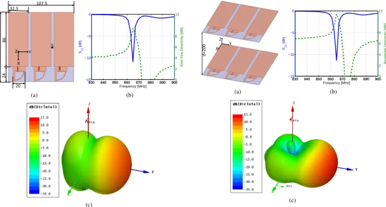
The initial unit-element used in this work is a miniaturized printed half-loop antenna [6]. It is printed on a 0.8mm-thick
Rogers RO4003 substrate and its dimensions are 24×20mm2.
A. Superdirective Unit-Element
The method described in [7] is used to design a three-element array for a 866M Hz with an inter-three-element distance of 0.1λ. The array is integrated in a Printed Circuit Board (PCB) via an analysis similar to the one presented in [8]. Fig. 1(a) shows the antenna geometry and dimensions in millimeters. The fully-driven array calculated excitation coefficients and 1This work was done with the funding of the French National Research Agency as part of the project "SOCRATE" and the support of the "Images et Reseaux" cluster of Brittany region, France.
the required optimal loads for transforming this array to a parasitic (loaded) one are given in Table I. The fully-driven array achieves a maximum simulated (ANSYS HFSS [9]) total directivity of 9.5dBi. However, as it can noticed, some negative resistances are required to transform this array to a parasitic one. Neglecting theses resistances, total directivities of 7.3dBi, 9.2dBi or 7.2dBi can be achieved in case of exciting the first-, second- or third- element. The highest directivity in the case of exciting the second element is due to two reasons. First, in this case, only one negative resistance is neglected. Second, the excitation coefficient of this element is the highest, and hence, the array directivity is more sensitive to the changes in this element’s excitation. Fig. 1(b) shows the parasitic antenna (exciting the second element and loading the first and third one with 68Ω//4.5pF , 0.6pF ) simulated end-fire directivity (D(θ=90o,ϕ=90o)) and input reflection coefficient
magnitude in dB. The figure shows that the end-fire directivity is maximum at the design frequency. The antenna has an
impedance bandwidth (S11 < −6db) of 2.8MHz and a
directivity bandwidth (Dmax− 1dB) of 2.6MHz. Fig. 1(c)
shows the antenna 3D total directivity radiation pattern at the resonance frequency (866M Hz). The figure shows a directive pattern with a maximum directivity of 9.2dBi in the end-fire direction. This directivity is 2.44dBi greater than Harrington’s normal directivity limit [10]. Fig. 3 shows the antenna 2D total directivity radiation patterns in horizontal (XoY) and vertical (YoZ) planes at the resonance frequency. The Half Power Beam-Width (HPBW) in horizontal and vertical planes are respectively 60◦ and 72◦. The Front to Back Ratio (FBR) is about 16.9dB. Due to the mutual coupling, the antenna presents a relatively small radiation efficiency (11.2%). Fi-nally, this antenna is significantly smaller than a Yagi-Uda antenna covering the same frequency band and with the same
directivity which dimensions are about 500× 152mm2 [11].
However, the miniaturization comes with some decrement in the antenna efficiency.
TABLE I. FULLY-DRIVEN ARRAY CALCULATED CURRENT EXCITATION COEFFICIENTS AND REQUIRED LOADS FOR TRANSFORMING THE ARRAY TO
A PARASITIC ONE
Element no. Magnitude [A] Phase [degree] Optimal Load [Ω]
1 1 0 17.9-j30
2 1.4 -146 -53-j45.3
(a) 830 840 850 860 870 880 890 900 −15 −10 −5 0 Frequency [MHz] S11 [dB] 830 840 850 860 870 880 890 9000 2 4 6 8 12
End−Fire Directivity [dBi]
(b)
(c)
Fig. 1. Superdirective unit-element geometry and simulated parameters. (a) Geometry and dimensions, (b) input reflection coefficient magnitude in dB and end-fire total directivity, and (c) 3D total directivity radiation pattern at the resonance frequency (866MHz).
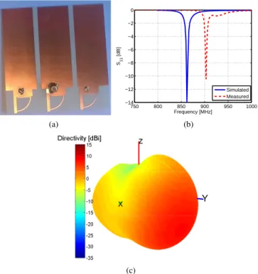
B. Compact Array Design
Two elements of the planar array are stacked along Z-axis with an inter-element distance of 200mm(0.6λ) as shown in Fig. 2(a). The two driven-elements are excited with equal power. Fig. 2(b) shows the antenna input reflection coefficient magnitude and directivity. The figure shows that the antenna’s total directivity is also maximal around the resonance fre-quency of 866M Hz. The antenna has an impedance bandwidth of 2.8M Hz and a directivity bandwidth of 3M Hz. Fig. 2(c) shows the antenna 3D total directivity radiation pattern. The figure shows a directive pattern with a maximum directivity of 11.6dBi in the direction (D(θ=90o,ϕ=90o)). Fig. 3 shows
the antenna 2D total directivity radiation patterns. The HPBW
in horizontal and vertical planes are respectively 56◦ and
42◦, the FBR is 17.2dB, and the Side Lobe Level (SLL) is
−11.4dBi. Finally, the antenna presents a radiation efficiency
of 9.7%. Comparing with the initial end-fire array, it can be noticed that the total directivity is increased by 2.4dB. The horizontal HPBW is almost the same, while the vertical one is divided by 1.7. As for antenna FBR and efficiency, they are approximately the same as the initial end-fire’s ones. This antenna is significantly smaller than equivalent (presents the same directivity) commercial antennas which dimensions are
about 698.5× 215.9 × 88.9mm3 [12]. (a) 830 840 850 860 870 880 890 900 −15 −10 −5 0 Frequency [MHz] S11 [dB] 830 840 850 860 870 880 890 9000 2 4 6 8 12
Broadside Directivity [dBi]
(b)
(c)
Fig. 2. Broadside array geometry and simulated parameters. (a) Geometry and dimensions, (b) input reflection coefficient magnitude in dB and end-fire total directivity, and (c) 3D total directivity radiation pattern at the resonance frequency (866MHz). −25 −15 −5 5 15 30 210 60 240 90 270 120 300 150 330 180 0 φ [°] Directivity [dBi] Planar array 3D array (a) −25 −15 −5 5 15 30 210 60 240 90 270 120 300 150 330 180 0 θ [°] Directivity [dBi] Planar array 3D array (b)
Fig. 3. Two arrays’ simulated 2D total directivity radiation patterns at the resonance frequency (866MHz). (a) Horizontal plane and (b) vertical plane.
III. DISTANCEEFFECT
To study the effect of the distance between the two par-asitic arrays (d) (refer to Fig. 2(a)), we change this distance from 0.01λ to 1.4λ while monitoring the antenna reflection coefficient, total directivity and radiation efficiency. Fig. 4(a) shows the array simulated input reflection coefficient mag-nitude as a function of the distance. The figure shows that for d = 0.01λ the array does not have any resonances in the observed band. This is due to the high mutual coupling. As the distance increases the mutual coupling decreases and the array resonance frequency converges to the one of the unit-elements. Fig. 4(b) shows the array simulated maximum total directivity and radiation efficiency as a function of the distance. The figure shows that for very small distances, the antenna’s efficiency is maximal and as the distance increases
the efficiency decreases. This is mainly due to the the lost of superdirectivity for very small distances. Fig. 5 shows the array simulated 2D total directivity radiation patterns at the design frequency as a function of the distance. The figure shows that for very small distances, the array directive pattern is lost and the array has a quasi-omnidirectional radiation pattern. This is also due to the high coupling effect that makes the applied loads unsuitable for having directive unit-elements. As the distance increases, the achieved directivity also increases till 1.2λ when it starts decreasing again.
830 840 850 860 870 880 890 900 −15 −10 −5 0 Frequency [MHz] S11 [dB] 0.01λ 0.2λ 0.4λ 0.8λ (a) 0 0.2 0.4 0.6 0.8 1 1.2 1.4 0 20 40 60 80 100 ηrad [%] d/λ 0 0.2 0.4 0.6 0.8 1 1.2 1.40 3 6 9 12 15 Dmax [dBi] (b)
Fig. 4. Broadside array simulated parameters as a function of the distance (d). (a) Input reflection coefficient magnitude in dB, and (b) maximum total directivity and radiation efficiency.
−25 −5 15 30 210 60 240 90 270 120 300 150 330 180 0 φ [°] Directivity [dBi] 0.01λ 0.2λ 0.4λ 0.8λ (a) −25 −5 15 30 210 60 240 90 270 120 300 150 330 180 0 θ [°] Directivity [dBi] 0.01λ 0.2λ 0.4λ 0.8λ (b)
Fig. 5. Broadside array simulated 2D total directivity radiation patterns at the resonance frequency (866MHz) as a function of the distance (d). (a) Horizontal plane and (b) vertical plane.
IV. EXPERIMENTALRESULTS
A prototype of the planar array was fabricated and mea-sured for results validation. Fig. 6(a) shows a photograph of the prototype. Fig. 6(b) shows the antenna measured input reflection coefficient magnitude in dB. The measured reso-nance is 903M Hz (4.7% shifted compared to the simulated one). This shift is mainly due to the coaxial cable effect and the dispersion of SMD components. Due to the antenna low efficiency, it is not easy to measure its far-field radiation pattern in the presence of a coaxial cable. Hence an optical probe from enprobe [13] was used and the measurements were performed in SATIMO stargate (SG 32) near-field measurement system. Fig. 6(c) shows the measured 3D total directivity radiation pattern at the resonance frequency (903M Hz). This pattern is in a good agreement with the simulated one. The measured directivity is 8.1dBi. Fig. 7 shows measured 2D total direc-tivity radiation pattens in horizontal and vertical planes. The HPBW in horizontal and vertical planes are respectively 67.5o
and 73o and the FBR is 8.5dB. The small difference may be
attributed to the measuring system and environment as well as the dispersion of SMD components.
(a) 750 800 850 900 950 1000 −14 −12 −10 −8 −6 −4 −2 0 Frequency [MHz] S11 [dB] Simulated Measured (b) Y (c)
Fig. 6. Planar array experimental results. (a) Fabricated prototype, (b) input reflection coefficient magnitude in dB and (c) 3D total directivity radiation pattern at the resonance frequency (903MHz).
−25 −5 15 30 210 60 240 90 270 120 300 150 330 180 0 φ [°] Directivity [dBi] Simulated Measured (a) −25 −5 15 30 210 60 240 90 270 120 300 150 330 180 0 θ [°] Directivity [dBi] Simulated Measured (b)
Fig. 7. Planar array measured 2D total directivity radiation patterns at the resonance frequency (903MHz). (a) Horizontal plane and (b) vertical plane.
V. CONCLUSION
In this paper, a parasitic end-fire three-element superdirec-tive antenna array for 866M Hz frequency band was proposed.
The array dimensions were (0.32λ×0.31λ) and it presented a
total directivity of 9.2dBi and radiation efficiency of 11.2%. The proposed array was, in turn, integrated in 3D array of total dimensions of (0.58λ× 0.32λ × 0.31λ) achieving a total directivity of 11.6dBi and radiation efficiency of 9.7%. This array is significantly smaller than classical arrays achieving the same directivity.
REFERENCES
[1] E. E. Altshuler, T. H. O’Donnell, A.D. Yaghjian, and S. R. Best, "A
Monopole Superdirective Array", IEEE Transactions on Antennas and
Propagation, vol. 53, no. 8, pp. 2653-2661, August 2005.
[2] T. H. O’Donnell, and A. D. Yaghjian, "Electrically Small Superdirective
Arrays Using Parasitic Elements", IEEE Antennas and Propagation
Society International Symposium 2006, pp. 3111,3114, 9-14 July 2006. [3] A. D. Yaghjian, T. H. O’Donnell, E. E. Altshuler, and S. R. Best
"Electrically Small Supergain End-Fire Arrays", Radio Science, vol. 43,
2008.
[4] P. Sharma, D. Arora, and H. Gupta, "Designing Superdirective Patch
An-tenna Array Using Metamaterial", International Journal of Engineering
Research & Technology (IJERT), vol. 1, issue 8, October 2012. [5] M. Pigeon, A. Sharaiha, and S. Collardey, "Miniature and Superdirective
Two Elements Endfire Antenna Array", 8th European Conference on
Antennas and Propagation (EuCAP 2014), pp. 3553-3556, 6-11 April 2014.
[6] B. Sentucq, A. Sharaiha, and S. Collardey, "Superdirective Compact
Parasitic Array of Metamaterial-Inspired Electrically Small Antenna",
International Workshop on Antenna Technology (iWAT), pp. 269,272, 4-6 March 2013.
[7] A. Haskou, A. Sharaiha, and S. Collardey, "Design of Small Parasitic
Loaded Superdirective End-Fire Antenna Arrays", IEEE Transactions on
Antennas and Propagation, vol. 63, no. 12, pp. 5456-5464, December 2015.
[8] A. Haskou, A. Sharaiha, and S. Collardey, "Integrating Superdirective
Electrically Small Antenna Arrays in PCBs", IEEE Antennas and
Wire-less Propagation Letters, doi: 10.1109/LAWP.2015.2425913. [9] ANSYS HFSS, Pittsburg, PA 15219, USA.
[10] R. F. Harrington, "On the Gain and Beamwidth of Directional
Anten-nas", IRE Transactions on Antennas and Propagation, pp. 219-225, July
1958.
[11] http://www.titanwirelessonline.com/v/vspfiles/assets/images/at-ya-9%20data%20sheet.pdf
[12] http://www.kpperformance.ca/product_documents/get/document/id/33/ [13] http://www.enprobe.de/products_FO-Links.htm