HAL Id: hal-02162405
https://hal.archives-ouvertes.fr/hal-02162405
Submitted on 21 Jun 2019
HAL is a multi-disciplinary open access
archive for the deposit and dissemination of
sci-entific research documents, whether they are
pub-lished or not. The documents may come from
teaching and research institutions in France or
abroad, or from public or private research centers.
L’archive ouverte pluridisciplinaire HAL, est
destinée au dépôt et à la diffusion de documents
scientifiques de niveau recherche, publiés ou non,
émanant des établissements d’enseignement et de
recherche français ou étrangers, des laboratoires
publics ou privés.
To cite this version:
Omar Krichen, Eric Anquetil, Nathalie Girard, Mickaël Renault. Online analysis of hand-drawn
strokes for Geometry learning. Marleah Blom; Nicola Nobile; Ching Y Suen. Frontiers in Pattern
Recognition and Artificial Intelligence, 5, World Scientific, pp.129-149, 2019, Language Processing,
Pattern Recognition, and Intelligent Systems, 9789811203527. �10.1142/9789811203527_0008�.
�hal-02162405�
Chapter 1
Online analysis of hand-drawn strokes for Geometry
learning
Omar Krichen, Eric Anquetil, Nathalie Girard, and Mickaël Renault Univ Rennes, CNRS, IRISA
F-35000, Rennes, France Email: [email protected]
This work takes place within the ACTIF project, in the context of the eFran call for projects that aims for active and collaborative learning promotion. This paper presents a pattern recognition and analysis sys-tem for Geometry learning in middle school. The goal is to allow stu-dents to draw geometric shapes on a pen-based tablet, given a teacher’s instruction. To make the student active, the system have to recognize and analyze on the fly the hand-drawn student’s productions in order to produce real-time visual, corrective, and guidance feedback. We base our work on the visual grammar CD-CMG1(Context Driven Constraints Multi-set Grammar), to model the domain prior knowledge and inter-pret the hand-drawn sketches on the fly. Our first contribution lies in adapting this grammar to the Geometry domain to cover the geometric objects taught in middle school curriculum. Although being expressive enough to model this large scope, the original formalism could not cope with the requirement of real-time analysis, given that the multiple inter-actions between geometric objects generate combinatorial issues. Our second contribution lies in extending the formalism to obtain acceptable performance for a real-time user interaction system. The first exper-iments on complex geometric figures drawing scenarios show that the proposed approach allows complexity and interpretation time reduction. We present also our result on another application domain, architecture plan sketching, to prove the generecity of our approach.
1. Introduction
Our work is in the context of e-FRAN ACTIF∗ project, which aims to use pen-based tablets in an educational context, mainly in French middle schools, to foster active learning.13 In this paper, we focus on learning Ge-ometry by drawing freely on a touch-tablet. Dynamic GeGe-ometry Software products are now an important part of teaching geometry. Their goal is to make geometric concepts understanding easier for the student by graphical construction, manipulation and visualization of figures. To our knowledge, the tools used in middle schools, Geogebra2 being one of the most widely used ones, rely on a drag-and-drop approach to manipulate geometric ob-jects. Indeed, in order to compose a figure, a student must choose from a graphical panel the object he wants to create then has to place its compo-nents in the interface. This tends to limit the creative process of the user. Fiorella and Mayer12 demonstrate that "generative drawing", i.e. learn-ing by drawlearn-ing, has a positive impact on students learnlearn-ing abilities in the classroom. Kluger and DeNisi14 show the impact of feedback intervention on learning performance. These two points represent the pedagogical foun-dation of our project. We propose a pen-based system that simulates the traditional pen and paper figure sketching and enriches it by real-time vi-sual, corrective and guidance feedback. This paper presents the first works done in the project, and focuses on the online recognition method of the system. The method is based on modelling the knowledge domain with a bi-dimensional formalism (CD-CMG grammar). Although the formalism is expressive, it could not cope with complexity of the application domain in terms of the handwritten strokes analysis time. We therefore optimized and extended this formalism have an acceptable performance in the con-text of real-time user interaction. In the literature several works have been done for hand-drawn sketches recognition, the following Sec. 2 presents an overview of existing approaches. Based on this overview and the applica-tion domain, we introduce the formalism in Sec. 3. Sec. 4 describes the formalism extension and its impact on the analysis process. Sec. 5 presents our experiments and results while conclusion and perspectives are given in Sec. 6.
∗ACTIF: Apprentissage et Collaboration sur Tablettes, Interactions et Feedback -
2. Related works
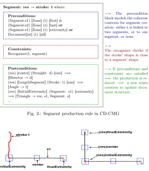
In this work, we are interested in on-line recognition of handwritten struc-tured documents. We distinguish between two types of handwritten doc-uments interpretations methods: lazy8 and eager9 (see Fig. 1). Lazy in-terpretation means that the analysis process begins after completion of the user’s production. Eager interpretation means that the handwritten strokes are analyzed on the fly, which is more relevant to our objective of having real-time corrective and guidance feedback to prevent error propa-gation.
Fig. 1.: Difference between eager and lazy interpretation: at left, the hand-written strokes, at right, analysis result and beautification
There are two major approaches for document analysis: statistical and structural. Statistical approaches3 rely on learning on large labelled databases to discriminate between symbols and are well suited for isolated shapes recognition. However, they do not allow the modelling of the doc-ument’s structure. Since we are in Geometry context, the system has to recognize not only the geometric shapes, but also the structural relations between the objects. Structural approaches consider a symbol in terms of its constituents, the graphical primitives, and the structural relations between them. For instance, a triangle is considered as three segments re-lated by spacial relations. Structural approaches rely on modelling prior domain knowledge by visual grammars. We distinguish between two classes of structural recognition methods. The former is based on graph gram-mars. For example, Zannibi et al.4 use labelled graphs to recognize hand-written mathematical expressions. One problem with graph-based methods is that they are complex to manipulate for the designer, especially if the production rules number is high. The latter is based on bi-dimensional grammars. For example, in5 Hammond and Davis proposed Ladder, a generic description language, and applied it for the interpretation of Truss
diagrams in a digital learning context.6 In7 a bi-dimensional extension to the Stochastic Context Free Grammar is proposed for handwritten mathe-matical expressions analysis. In this work, to model the geometry domain knowledge, we prefer to use Context Driven Constraints Multi-set Gram-mar1 (CD-CMG), a generic formalism for eager interpretation of hand drawn documents. Indeed, in this grammar, the context is explicitly spec-ified in the production rules, which reduces the search space. Moreover, this formalism is the combination between a statistical approach (to locally recognize a shape) and a structural approach (to model the global structure of the document). Finally, CD-CMG has been applied to various types of documents such as architectural plans10 or electrical sketches.1 All these features show this formalism is well adapted for our purpose. Thereafter, our contribution lies in twofold: adapting this grammar to the Geome-try domain for e-education (see Section 3), and extending this formalism to match the constraint of real-time analysis of geometric productions (see Section 4). Moreover, we have to ensure that our extension of the formalism is coherent with the genericity aspect of CD-CMG, i.e. that our optimiza-tion not only improve the system’s performance in the geometry sketching domain, but also on other applications. In Section 5, we present the impact of the formalism extension on the analysis complexity in two different but related domains: geometry sketching and architecture plan sketching. 3. Geometry domain modelling
In this section, we present the formalism, and illustrate it through its adap-tation to the Geometry domain.
3.1. Context Driven Constraints Multi-Set Grammar
As an extension of the well-known grammar CMG,11 CD-CMG is formally defined as follows:
Definition 1. A CD-CMG is a tuple G=( VN, VT, S, P) with: • VN: the set of non terminal symbols = symbol classes; • VT: the alphabet, here VT= {stroke};
• S: the first symbol, or axiom; • P: the set of production rules.
And where a production rule p ∈ P is composed of three blocks allowing different levels of vision on the document. The precondition and the
postcondition blocks stand for the global vision of the document while the constraint block stands for the local vision of the analyzed strokes. Therefore, a production rule p is denoted as follows:
α → β Preconditions Constraints Postconditions | α ∈VN+, β ∈ (VT ∪VN)+
Preconditions and postconditions are based on the concept of Document Structural Context, which models a zone in the document and the awaited elements in it, defined as follows:
Definition 2. A DSC is defined by (λ)[position](γ)[part] where: • λ is a set of reference elements;
• position is a zone (i.e. a position) related to λ; • γ is a set of awaited symbols in this zone;
• part is a part of the awaited symbol that has to intersect the zone. The preconditions are a set of DSC that have to be satisfied and repre-sent the context in which β can be replaced by α. The postconditions are a set of DSC that represent the objects that can be created from the new re-duced elements α. This formalization enables to drive the analysis process by the context. Indeed, the preconditions represent the verification step while the postconditions represent the prediction step. The constraints model a local vision on the analyzed elements β. They have two purposes: checking that the shape of β is consistent with the production, and decide if it is pertinent to reduce β into α
3.2. Adaptation of CD-CMG to Geometry
We consider the main geometric objects taught in French middle schools: segments, arcs, circles, angles, all the types of triangles and quadrilaterals. We defined around 20 productions rules to model these objects productions as well as the interactions between them (e.g. intersection and orthogonal-ity). Let’s illustrate this with two production rules.
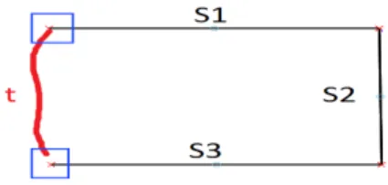
Fig. 2 presents a part of a segment production rule, while Fig. 3 and Fig. 4 illustrate a segment composition. In this example, the red stroke in Fig. 3 is transformed into a segment if the precondition block and the constraint block are satisfied. The first postcondition DSC in the Post-Conditions block (green rectangle in Fig. 2) models the fact that a bisector
production rule will be triggered if a straight d intersects the center zone of the new created segment (res).
Segment: res → stroke: t where: Preconditions:
(Segment:s1) [Zone] (t) [first] & (Segment:s2) [Zone] (t) [last] or (Segment:s1) [Zone] (t) [extremity] or Document[int] (t) [all]
Constraints:
Recognizer(t, segment)
Postconditions
(res) [center] (Straight: d) [one] =⇒ [Bisector → d]
(res) [LengthSegment] (Stroke: t) [one] =⇒ [Angle → t]
(res) [InitialExtremity] (Segment: s1) [extremity] =⇒ [Triangle → res, s1, Segment: s]
...
−→ The precondition block models the coherent contexts for segment cre-ation: either t is linked to two segments, or to one segment, or none
−→
The recognizer checks if the stroke’ shape is close to a segment’ shape
−→ If preconditions and constraints are satisfied =⇒ the production is re-duced =⇒ a new zones creation to update docu-ment structure
Fig. 2.: Segment production rule in CD-CMG
Fig. 3.: Drawn stroke (in red) Fig. 4.: Interpreted segment Fig. 5 illustrates the production rule of a scalene triangle. The precondition block is composed of one precondition which is a conjunction of three DSC modelling the fact that each segment intersects a zone related to the other two. The constraint here is structural, such that it verifies that the three segments are linked by their extremities. Since the structural context is the same for all types of triangles (and quadrilaterals as well),
Triangle: res → segment: s1, s2, s3 with: Preconditions:
(S1) [Zone] (s2) [one] & (S2) [Zone] (s3) [one] & (S3) [Zone] (s1) [one] Constraints:
LinkedSegments(s1, s2, s3) Postconditions:
(res)[TriangleZone] (Circle: c) [All] =⇒ [Inscribed-Circle → c]
Fig. 5.: Triangle production rule
we established a hierarchy between production rules, from general to specific, in order to prune the search space and speed up the analysis process. For example, a triangle can be reduced into an isosceles triangle if two of its sides are equal.
3.3. Analysis process associated to CD-CMG
The analysis process, extensively explained in,1 is a combination of a bottom-up strategy (guided by the reduced elements) and a top-down strat-egy (guided by the postconditions DSCs). For each new element, the parser searches the DSC it satisfies and vice versa. Consequently, a production is triggered if its β elements contain at least a new element and its precondi-tion block contains at least a new DSC. Let’s consider the scene illustrated in Fig. 6 composed of a new stroke t (in red) and three segments (s1, s2, s3).
Fig. 6.: Stroke analysis process
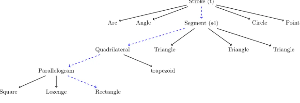
The analysis of t leads to the construction of the analysis (or derivation) tree presented in Fig. 7. The root represents the stroke t. The nodes and the leaves represent the triggered rules, while the blue path is the sequence of reduced production rules, i.e. the analysis result. As shown in Fig. 7, t is first reduced into a segment, denoted thereafter s4. Then, several
rules are tested among which the production rules that led to the correct interpretation of the user’s drawing. The exploration strategy is explicit for each rule. For basic shape creation, the strategy is breadth-first, i.e. the analyzer checks if the stroke is either an arc, an angle, a segment, a cir-cle, or a point. Each production rule is associated with a score, depending on the adequacy with the preconditions and the constraints. If there are more than one possible interpretation (two applicable productions at the same analysis level for example), the analyzer expands the analysis tree, and chooses the sequence of productions with the highest score. For other productions, such as triangle creation, the exploration strategy is depth-first, such as the first applicable rule is reduced without considering the other alternatives. This allows to reduce the search space.
3.4. Limits of CD-CMG in geometry
As we can see in Fig. 7, the triangle production rule is triggered three times for each possible combination of segments: (s4, s1, s2), (s4, s1, s3) and (s4, s2, s3), even if there is no coherent context for creating a triangle in this scene. This is due to the fact that these productions contain a new element (s4) and one of their preconditions DSC is satisfied (c.f. Fig. 6). Only the precondition block is checked in this case, since not all DSC are satisfied. The impact on the combinatorics is not important here, but when the doc-ument is complex, the analysis becomes costly. Even though the formalism is generic and expressive enough to model the prior geometry knowledge, the multiple possible interactions between geometric objects, e.g. creating sub-figures from existing ones (c.f. Fig. 8), also generate combinatorial problems in the analysis process.
Let’s consider the triangle production rule (c.f. Fig. 5). A direct
conse-Stroke (t) Segment (s4) Angle
Arc Circle Point
Triangle Triangle
Triangle Quadrilateral
Parallelogram trapezoid Square Lozenge Rectangle
(a) Drawn stroke (in blue) (b) 2 Triangles and 1 quadrilateral Fig. 8.: Sub-figures creation
quence of adapting CD-GMC to the geometry domain is that the β elements (here the 3 segments) are not really replaced by the α elements (here the triangle). They contribute to create the triangle but they remain consid-ered in the analysis process in order to create other new elements. This has a big impact on the applicable rules search space size. We identify two factors producing the combinatorial explosions: the format of the DSCs, and the computation of equivalent interpretations. We will explicit these factors and our proposed solutions in the next section.
4. Revision and formalism extension
In this section, we present the problems we faced in terms of analysis process complexity and our proposed solutions.
4.1. The DSC problematic
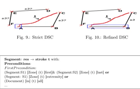
The expressivity of the formalism in terms of describing the document struc-ture with the DSC allows to formalize that all the components of a polygon are linked by their extremities. Unfortunately, as we have seen in Section 3.C, the fact that a production can be triggered even if only one of its preconditions DSC is validated generates a combinatorial problem. Indeed, the more segments a polygon contains, the more DSC there are in the poly-gon production. Fig. 9 illustrates the composition of a new stroke t in the context of three already interpreted segments. t will be recognized as a new segment called thereafter s2. The fact that s2 is linked to [AB] (blue zone in Fig. 9) will activate the DSC:
[AB] [InitialExtremity] s2 [one] =⇒ triangle → [AB],s2,s3.
The parser will search the third segment (i.e. s3) that completes the triangle rule with [AB] and s2. There is no contextual information in this DSC about the segment [BC] that completes the triangle since it is not con-cerned by the zone [AB] [InitialExtremity]. In consequence, for this scene
composed of 3 segments besides [AB] and s2, the triangle production rule will be tested three times (for s3=[BC], s3=[ED] and s3=[EF]) instead of once. Thus, the analysis time can be very long, especially if the document is complex. In fact, this issue relies on a CD-CMG limitation. The formalism does not allow to have more than one zone in a DSC, which would enable positioning many awaited elements in relation to one reference element. To resolve this problem, we propose to refine the constraints on the zonessuch that a zone can cover all the awaited symbols in the same DSC. The DSC related to the triangle production rules will then be:
[AB] [T otalLengthSegment] s2, s3 [one],
where T otalLengthSegment is the zone that covers the length of [AB] (in blue in Fig. 10). This formulation allows to have a contextual information on all the segments composing a triangle. The loss in focus of the zone (from covering an extremity to covering all the segment) is balanced in the Constraintblock by verifying that the segments are structurally linked by their extremities. For the scene illustrated in Fig. 10, the triangle produc-tion rule is triggered only once, which reduces the analysis complexity.
Fig. 9.: Strict DSC Fig. 10.: Refined DSC
Segment: res → stroke t with: Preconditions:
F irstP recondition:
(Segment:S1) [Zone] (t) [first]& (Segment:S2) [Zone] (t) [last] or (Segment: S1) [Zone] (t) [extremity] or
(Document) [in] (t) [all] ...
4.2. Problem of equivalent interpretations and formalism extension
Since we are in Geometry learning context, it is important to know the de-pendency links between the elements, e.g. the connections between several segments. These links are modeled in the preconditions DSCs. Fig. 11 presents a focus on the precondition block of the segment production rule. It is composed of a disjunction of three preconditions. They model the fact that there are three possible contexts for a segment creation. The stroke can be linked to two existing segments by their extremities, or linked to the extremity of only one segment, or not linked to anything (in the document). The F irstP recondition operator, introduced in,10 establishes an order be-tween the preconditions, e.g. from specific to general, and forces the parser to stop the context research at the first valid precondition.
Fig. 12.: FirstPrecondition limits
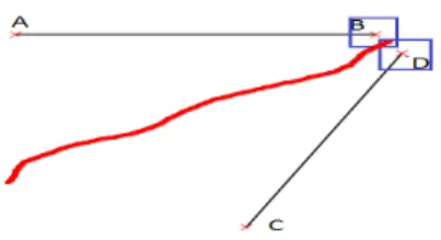
Fig.12 illustrates a scene in which a stroke t is recognized as a segment. F irstP reconditionforces the parser to consider the stroke as linked to two segments, considering only the first precondition. Without this operator, the three preconditions, which are valid in this case, will be tested as hy-potheses. The parser will expand the analysis tree in a breadth-first manner then choose the interpretation with the highest score.
A limit to this operator is that the verification of the first precondition can also be complex. Indeed, in this example, there are six contextually valid hypotheses: t can be linked to the couples (s1, s5), (s1,s6), (s1, s7), (s4, s5), (s4, s6), (s4, s7). Hence, six equivalent branches will be created in the analysis tree multiplying the analysis complexity by six. The issue is that the existing grammar does not include alternative strategies to deal with
these hypotheses. The context search will then be exhaustive, generating in consequence combinatorial problems, where in fact the six hypotheses mentioned above are equivalent. To tackle this problem, we propose to extend the formalism by creating a new operator F irstContext. This op-erator forces the parser not only to stop the research at the first valid precondition, but also at the first valid context within a precondition. It means that the search is stopped when the first reference elements that are coherent with the precondition are found. In the example (Fig. 12), the parser will choose the first couple of segments that satisfies the DSCs of the preconditions, e.g. it will choose the couple (s1, s7) without consider-ing the other combinations. This means we have an alternative exploration strategy enabling to reduce the search space. This will drastically reduce complexity, without losing information about connections. In use, we have noticed a limit to this new operator, which occurs when the segments are not exactly connected, but have overlapping zones (see the example in Fig. 13). Without the F irstContext operator, the system computes the
mem-Fig. 13.: Zone overlap problem
bership degree of the stroke’s extremity in each zone of the segments to choose the best possible interpretation. With F irstContext operator, it has to choose the first valid interpretation, which is not necessarily the best. However, the robustness of this extension lies in the interaction with the user since he has the possibility to implicitly validate the interpretation by continuing his drawings, or to delete the segment and redraw it more precisely. This is a trade-off between interpretation precision and analysis process. We will detail the impact of our contributions in the next section.
5. Experiments and results
5.1. Quantitative study on Geometry domain
To evaluate the impact of our contributions on the system performance, we established several criteria:
• Iterations: number of reduced productions rules
• Interpretations: number of branches in the analysis tree • Time: Analysis time
• Triggered: Number of triggered rules
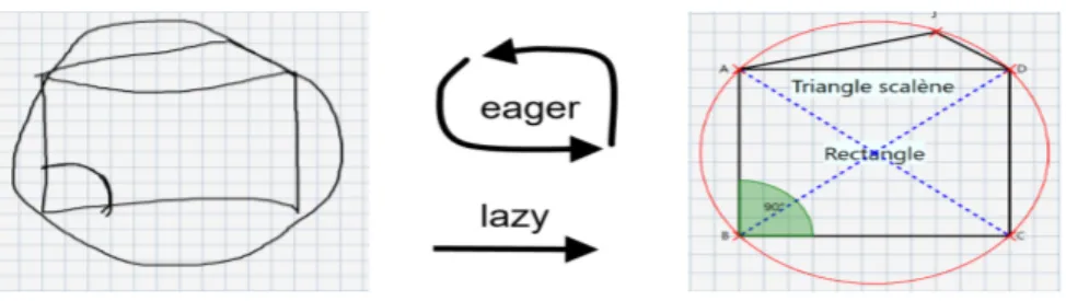
The evaluation is realized on one complex drawing benchmark, illustrated in Fig. 14.
Fig. 14.: Benchmark
We study the impact of our contributions on three critical steps of the drawing scenario of this figure, illustrated in Fig. 15, Fig. 16, and Fig. 17. We compare the performance of our system with the existing CD-CMG grammar and its associated parser. In the following, the term ZoneOpt refers to the constraints refinement on the zones while F irstContext refers to the formalism extension by the addition of the new operator.
5.1.1. First step of the scenario
The scene (Fig. 15) illustrates a drawn stroke that will produce an analysis process. The stroke will be first interpreted as segment [AD]. This segments will trigger the production of a rectangle.
TABLE 1 presents the analysis results for this step.
Since the document is still simple, the performance is good (around 0.20 seconds). However, our contributions have no real impact on the analy-sis time. With ZoneOpt, the number of triggered rules decreases from 43
Drawn stroke Analysis result Fig. 15.: First step of the scenario
Table 1.: First step analysis result
Approach Iterations Interpretations Time Triggered
DALI 4 1 0.23 s 43
ZoneOpt 4 1 0.20 s 23
F irstContext 4 1 0.20 s 43
ZoneOpt+ F irstContext 4 1 0.19 s 23
to 23. F irstContext operator has no effect since there is no equivalent interpretations to consider.
5.1.2. Second step of the scenario
The scene (Fig. 16) illustrates a more complex production. The drawn stroke will be first interpreted as segment [EB]. This segments will trigger the production of two triangles, one being isosceles and the other rectangle.
Drawn stroke Analysis result
Fig. 16.: Second step of the scenario
The impact of our contributions on this step is illustrated in TABLE 2. With the existing formalism, the performance is not acceptable since anal-ysis time takes 6.4 seconds. This is due to the number of triggered rules (1057) and equivalent interpretations (3). By modifying the format of the
Table 2.: Second step analysis results
Approach Iterations Interpretations Time Triggered
CD-CMG 15 3 6.4 s 1057
ZoneOpt 15 3 2 s 330
F irstContext 5 1 4.2 s 356
ZoneOpt + F irstContext 5 1 0.62 s 113
DSCs, ZoneOpt improves the analysis time (2s) by reducing the number of triggered rules. F irstContext operator forces the parser to consider only one interpretation. In consequence, the number of triggered rules decreases from 1057 to 356, and the analysis time is down to 4.2 seconds, which is still not acceptable in a context of real-time interaction with a user. However, the coupling of Opt1 and Opt2 enables to have an analysis time of 0.62 which is acceptable.
5.1.3. Third step of the scenario
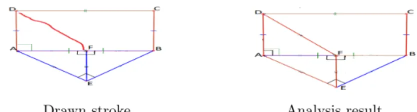
In this final step of the scenario (illustrated in Fig. 17), the drawn stroke will be first interpreted as segment [DF]. This segment will trigger the pro-duction of right-angled triangle, a trapezoid and a parallelogram.
Drawn stroke Analysis result
Fig. 17.: Third step of the scenario
For this step of the scenario, the coupling of ZoneOpt and F irstContext en-ables to decrease the analysis time from 30 seconds to only 1.5 seconds. As we can see from TABLE 2 and TABLE 3, the more complex the scene gets, the greater the impact of our contributions on the performance gets. Thus, taking into account the desired real-time user interaction, the proposed optimization allow the design of a system with acceptable performance.
Table 3.: Third step analysis results
Approach Interpretations Analysis time Triggered rules
CD-CMG 6 30 s 2472
Extended zones 6 7 s 962
F irstContext 1 5 s 412
Extended zones+ F irstContext 1 1.5 s 167
5.2. Quantitative study on Architecture domain
To prove the genericity of our approach, we adapt our extension of CD-CMG to the Architecture sketching domain. The previous version of the formalism was already applied in this domain as mentioned before in Section 2. The elements are walls, editable doors and windows. We add the possibility to recognize rooms, which are modelled by polygons. This adds another layer of complexity which wasn’t incorporated until now. More-over, the analysis engine is not only capable of detecting newly created rooms, but also to create what we call "implicit rooms" (elements that are not displayed), which are determined by the combinations of all the connected rooms in the scene (c.f. Fig. 18). This is an important
func-Fig. 18.: Explicit rooms (piece 2 and piece 3), one implicit room (piece 1) tionality because we want to be able to maintain the notion of a created room, even after deleting a wall connecting two adjacent rooms. As we can see in Fig. 19, after the deletion of "chamber 4", "couloir" (corridor in French), and "salle a manger" (dining room), the implicit room "pièce 14" becomes explicit and is displayed in the scene. We study the impact of our formalism extension (mainly the FirstContext operator) on a complex drawing scenario illustrated in Fig. 20. The red stroke will lead to the creation of segment, which will lead to the creation of 29 "implicit" rooms, and one visible room ("chambre 1"). We study the impact of our optimiza-tion using the same criteria as in Geometry sketching domain. We can see
Deleting 4 explicit rooms Scene post-deletion Fig. 19.: Complexity of architecture domain
Drawn stroke Analysis result
Fig. 20.: Drawing scenario for architecture plans domain Table 4.: Third step analysis results
Approach Interpretations Analysis time Triggered rules
CD-CMG 9 2.09 s 760
Extended formalism 1 0.22 s 92
from TABLE 4 that the extension of the formalism with the FirstContext operator, enabling to choose alternative strategies for context search, has the consequence of dividing nearly by 10 the analysis time, from 2.09 to 0.22 seconds. We can then say that our extension is coherent with the generic aspect of the formalism.
5.3. Qualitative study
As shown in Fig.21, we have implemented a pen-based prototype for the composition of geometric sketches. The real-time analysis of the user’s composition allows to give visual feedback, which are signs that the system has correctly interpreted the hand-drawn figures (see angle recognition in green in Fig.21).
To respect to continuum with pen and paper habits, the system has to be flexible enough in order to make the exercise execution as intuitive for the child as possible. For example, the construction of a parallelogram needs a level of precision that can interfere with our free drawing objective. Therefore, we integrated an edition mode to our system to facilitate the drawing process.
Fig. 21.: Prototype interface 5.3.1. Edition mode
We propose edition functions for the user, such as the ability to modify angles, force segments equality and manage parallelism and orthogonality, plus a protractor and compass tools. These features are important in the context of geometric figure composition, such as drawing a parallelogram with certain constraints on segments length and angles. Orthogonality and equality symbols are integrated in the grammars, whereas the tools are un-related from the formalism, and are for creating arcs, circles or angles with the desired precision. Fig. 22 represents the production rule for equality coding (two equality signs drawn on two segments to modify the length of the last one), while Fig. 23 illustrates the drawing process and the analysis result.
Segment: res → segment: s1, EqualitySign: eq1, EqualitySign: eq2 with: Preconditions:
(s1) [Zone] (eq1) [one] & (s2) [Zone] (eq2) [one] Constraints:
OrderBetweenSegments(s1, s2) Postconditions:
Fig. 22.: Equality coding production rule
drawn stroke in red forcing equality propoerty Fig. 23.: Including geometry codes in CD-CMG
5.4. First user experiments
We work closely with our partners in ergonomics and usages (Loustic, LP3C), in our user-centered design. They conducted the first user ex-periments on a beta version of the system, with 12 volunteer children from a Brittany region middle-school. The objective was to perform a simple exercise in a short time (5 minutes, after 5 minutes of training). Even if some children encountered difficulties in completing the task, due to some system imperfections and lack of training time, the post-test questionnaire showed a prevailing feeling of satisfaction from the pupils and the teachers towards our application and its potential.
6. Conclusion and perspectives
In this paper, we propose a pen-based system that interprets in real-time geometric figures, based on the modelling of the prior domain knowledge with a bi-dimensional grammar. We optimize and extend the CD-CMG formalism to adapt it to the geometry domain. Our formalism extension is coherent with the genericity aspect of the grammar, as we has proven
when adapting CD-CMG to the architecture domain. Our contributions have a consequent impact on the system performance which is now accept-able for real-time user-interaction. Our future work consist in improving even more the analysis time, one possible solution being the modification of the analysis process in terms of triggering rules. Given that there multiple layers of interpretation (basic shapes, polygons, etc), the idea would be to extend the grammar to include the notion of hierarchy between produc-tion rules. We will also work on the semantic interpretaproduc-tion of the child’s drawing. The goal is to enable the teacher to create customized exercises. The system will be generate automatically the solver procedure from the teacher’s drawings. Given that there are more than one possible solution for solving the exercise, we will have to generate all the alternative solutions as sequence of actions. The goal is for the system to detect in real-time from the child’s actions the solution that he intends to realize and guide him accordingly. The successive versions of our prototype will be tested in pilot middle schools to validate our approach, and we will benefit from the studies of LP3C and LOUSTIC laboratories in usage psychology and ergonomics to be aware of the users needs and preferences in terms of vi-sual and corrective feedback, and other features such as virtual manipulable tools.
Acknowledgment
"ACTIF" is funded by the region of Brittany and the French state call for projects e-FRAN, operated by the "Caisse des Dépôts". The project is supported by the LabCom « ScriptAndLabs » (n° ANR-16-LVC2-0008-01). The authors would like to tank the academic partners, the LP3C and LOUSTIC.
References
1. S. Macé, E. Anquetil, “Eager interpretation of on-line hand-drawn struc-tured documents: The DALI methodology“, Pattern Recognition 42, 2009, pp. 3202–3214.
2. K. Bhagat, C-Y. Chang, “Incorporating GeoGebra into geometry learning – A lesson from India“, Eurasia Journal of Mathematics, Science & Technology Education, 11 (1), 2015, pp. 77–86
3. A. Delaye, E. Anquetil. “Hbf49 feature set : A first unified baseline for online symbol recognition“, Pattern Recognition 46(1), 2013, pp. 117-130.
recognition for handwritten math via primitive label graphs“, Document Recognition and Retrieval XX, 2013, pp. 1–11.
5. T. Hammond, R.Davis, “LADDER, A Sketching Language for User Interface Developers“, Computers & Graphics 29, 2005, pp. 518-532.
6. O. Atilola, S. Valentine, H.H. Kim, D. Turner, E. McTigue, T. Hammond, J. Linsey, “Mechanix : A natural sketch interface tool for teaching truss anal-ysis and free-body diagrams“, Artificial Intelligence for Engineering Design, Analysis and Manufacturing 28, 2014, pp. 169-192.
7. Á. Muñoz, F.S. Peiró, J.B. Ruiz, “Recognition of on-line handwritten mathe-matical expressions using 2D stochastic context-free grammars 48 and hidden Markov models“, Pattern Recognition Letters 35, 2014, pp. 58-67.
8. A. Ghorbel, A. Lemaître, E. Anquetil, S. Fleury, E. Jamet. “Interactive inter-pretation of structured documents : application to the recognition of hand-written architectural plans“, Pattern recognition, 48(8), 2015, pp. 2446-2458. 9. E. Lank, J. Thorley, S. Chen, D. Blostein, “On-line recognition of UML diagrams“. Document Analysis and Recognition, 2001. Proceedings. Sixth International Conference on Document Analysis and Recognition, 2001, pp. 356–360.
10. M. Pecot, S. Macé, E. Anquetil. “Interprétation interactive de plans d’architecture composés à main levée“. Actes du XIème Colloque Interna-tional Francophone sur l’Ecrit et le Document (CIFED’10), 2010, pp. 185-200.
11. K. Marriott. “Constraint multiset grammars“. In Proceedings of the IEEE Symposium on Visual Languages, (VL’94), 1994, pp. 118–125.
12. L. Fiorella, R.E Mayer. “Learning as a generative activity: Eight learning strategies that promote understanding“. Cambridge University Press, 2015. 13. A. W. Chickering, S. C. Ehrmann. “Implementing the seven principles:
Tech-nology as lever“. AAHE Bulletin, 49, 1996, pp. 3–6.
14. A. N. Kluger, A. DeNisi. “The effects of feedback interventions on perfor-mance: A historical review, a meta-analysis, and a preliminary feedback intervention theory“. Psychological Bulletin, 119, 1996, pp. 254-284.