HAL Id: hal-01450517
https://hal.archives-ouvertes.fr/hal-01450517
Submitted on 15 Feb 2017
HAL is a multi-disciplinary open access
archive for the deposit and dissemination of
sci-entific research documents, whether they are
pub-lished or not. The documents may come from
teaching and research institutions in France or
abroad, or from public or private research centers.
L’archive ouverte pluridisciplinaire HAL, est
destinée au dépôt et à la diffusion de documents
scientifiques de niveau recherche, publiés ou non,
émanant des établissements d’enseignement et de
recherche français ou étrangers, des laboratoires
publics ou privés.
A Domain-specific Language for The Control of
Self-adaptive Component-based Architecture
Frederico Alvares, Eric Rutten, Lionel Seinturier
To cite this version:
Frederico Alvares, Eric Rutten, Lionel Seinturier. A Domain-specific Language for The Control
of Self-adaptive Component-based Architecture. Journal of Systems and Software, Elsevier, 2017,
�10.1016/j.jss.2017.01.030�. �hal-01450517�
A Domain-specific Language for The Control of Self-adaptive Component-based
Architecture
Frederico Alvaresa, Eric Ruttenb, Lionel Seinturierc
aMines-Nantes& INRIA Bretagne & LINA
Nantes, France [email protected]
bINRIA Rhˆone-Alpes
Grenoble, France [email protected]
cUniversit´e Lille 1& INRIA Lille
Lille, France [email protected]
Abstract
Self-adaptive behaviors in the context of Component-based Architecture are generally designed based on past monitoring events, configurations (component assemblies) as well as behavioural programs defining the adaptation logics and invariant properties. Providing assurances on the navigation through the configuration space remains a challenge. That requires taking decisions on predictions on the possible futures of the system in order to avoid going into branches of the behavioural program leading to bad configurations. This article proposes the design of self-adaptive software components based on logical discrete control approaches, in which the self-adaptive behavioural models enriches component controllers with a knowledge not only on events, configurations and past history, but also with possible future configurations. We present Ctrl-F, a Domain-specific Language whose objective is to provide high-level support for describing these control policies. Ctrl-F is formally defined by translation to Finite State Automata, which allow for the exploration of behavioural programs by verification or Discrete Controller Synthesis, i.e., by automatically generating a controller to enforce correct self-adaptive behaviours. We integrate Ctrl-F with FraSCAti, a Service Component Architecture middleware platform and we illustrate the use of Ctrl-F by applying it to two case studies: a news web application and a mutual exclusive task workflow.
Keywords:
Component-based Architecture, Self-adaptation, Discrete Control 2000 MSC:, 10.040, 10.280, 10.090, 10.050, 20.120
1. Introduction
Architecting software-intensive systems has become a chal-lenging task. From tiny applications embedded in house ap-pliances or automobiles, passing through highly connected cy-ber physical systems, to huge and distributed services in the Cloud, nowadays software systems have to fulfill a number of requirements in terms of operational cost, safety and Quality of Service (QoS) while facing highly dynamic environments (e.g., varying workloads and changing user requirements) and plat-forms (e.g., software/hardware resource availability and fail-ures). That level of dynamicity makes it difficult, often almost impossible, to manage such software systems in a manual way. It becomes thus imperative to engineer and architect with prin-ciples of self-adaptiveness in mind, i.e., to equip these software systems with capabilities to cope with environmental and con-textual changes occurring at runtime.
The design of such complex computing systems has been improved by the help of structural organization support of component-based architecture, in which software components encapsulates functionalities that can be accessed through
well-defined interfaces that do not depend on their particular imple-mentations. In addition to the benefits of modularity and reuse [1] – which are consequences of this structural organization – adaptability and reconfigurability are key properties which are sought with this approach: one wants to be able to adapt the component assemblies (configurations) in order to cope with new requirements and new execution conditions occurring at runtime.
Architecture Description Languages (ADLs) captures the high-level structure of software systems by describing how they are organized by the means of a composition of com-ponents. In order to attain self-adaptation, ADLs are gen-erally used to define initial configurations, whereas adaptive behaviours are achieved by programming fine-grained actions (e.g., to add, remove, connect elements), in either general-purpose languages within reflective component-based middle-ware platforms [2, 3, 4], or with the support of reconfiguration domain-specific languages (DSLs)[5, 6]. This low level of ab-straction may turn the definition of transitions among configu-rations into a very tedious and costly task, which consequently
may lead to error-prone adaptive behaviours. In fact, it may be non-trivial, especially for large and complex architectures (e.g., web applications with hundreds/thousands of replicated components with specific tuning parameters and constraints), to conceive well-mastered self-adaptive behaviours, with as-surances on the way the navigation through the configuration space is performed. Our previous work [7] tackles this problem by proposing a DSL that extends classic ADLs with high-level constructs to describe adaptation in software components by means of behavioural programs, i.e., in terms of order and/or conditions under which reconfigurations take place; and poli-cies, i.e., constraints that have to be enforced all along the exe-cution.
Adaptation decisions are taken at runtime by choosing the next configuration (e.g., a set of architectural elements) in func-tion of not only the observed past history (monitoring events, states, configurations), but also on behavioural programs de-scribing the adaptation logics and properties to be kept invari-ant all over the managed system’s execution [8][9]. That form of decision must involve not only updating the current advance-ment in the behaviors, but also some predictions on the possible futures of the system. These guarantees can be achieved with the support of control theoretical approaches, where the use of behavioural models allows for predictive decisions. Control-based approaches for software systems have been investigated, mainly concerning quantitative aspects and using continuous control [10]. The use of discrete control is however more ap-propriated in the context of this work, since the purpose here is to choose configurations in a logical-basis. In particular, we address the design of such a decision-maker as a Discrete Con-troller Synthesis (DCS) problem [11], which consists in auto-matically generating a controller capable of controlling a set of input variables such that a given temporal property is satisfied.
We propose the design of software components based on Fi-nite State Automata (FSA) behavioural models, which provide knowledge on events, states, past history as well as on possible futures, i.e., the space of reachable configurations. This way, we are be able to, by control, avoid going into behavioural pro-gram branches leading to wrong configurations. For that pur-pose, we formally define the semantics of Ctrl-F behavioural programs by the translation to a FSA model [12]. More pre-cisely, we provide full translation from Ctrl-F to the reactive language Heptagon/BZR [13], which allows the compilation to-wards formal tools and thereby benefit from exploration by both DCS and verification.
Since the combinatorial complexity of that formal explo-ration can be exponential in the number of configuexplo-rations and hence very costly to be performed at runtime, and given that adaptive behavioural programs can be known in advance, we advocate that the DCS should rather be performed off-line. That is to say that controllers are compiled away so as to provide cor-rect solutions at runtime. Furthermore, this is done in a max-imal permissive way, meaning that besides ensuring the cor-rectness of decisions, the generated controller makes it optimal, in the sense that it keeps the maximum of possible configura-tions not violating the stated policies, and hence making the controlled system maximally flexible. The result of the
compi-lation of a given behavioural program is an executable function which, at each decision step, takes the current state and current events, and returns a control value corresponding to the next configuration such that the stated policies are respected.
This article extends our previous work [7] and presents a de-tailed description of Ctrl-F language as well as its translation into Heptagon/BZR. In addition, we provide further details on its implementation and integration with FraSCAti [4], a mid-dleware allowing for runtime reconfiguration of Service Com-ponent Architecture (SCA) software systems. We also illustrate our approach throughout two case studies: a news web applica-tion, with QoS and cost requirements [14]; and an application with mutual exclusion requirements. Finally, we provide a dis-cussion on the applicability of our approach by executing these applications under different scenarios.
The remainder of this article is organized as follows. Sec-tion 2 introduces the main concepts necessary to understand our approach. Section 3 presents the Ctrl-F language. Its com-pilation to Heptagon/BZR is detailed in Section 4. Section 5 provides some details on the integration of Ctrl-F with a FraS-CAti middleware platform. Section 6 presents some case stud-ies and provides some discussion on the applicability of our approach. Related work is discussed in Section 7 and Section 8 concludes this article while pointing out some perspectives for future work.
2. Background
2.1. Component-based Software Architecture 2.1.1. Architecture Basics and Description Language
Software architectures define the high-level structure of soft-ware systems by describing how they are organized by the means of a composition of components [1]. Architecture de-scription languages (ADLs) [15] are usually used to capture these architectures. Although the diversity of ADLs, the ar-chitectural elements proposed in almost all of them follow the same conceptual basis [16]. A component is defined as the most elementary unit of processing or data and it is usually decom-posed into two parts: the implementation and the interface. The implementation describes the internal behaviour of the actual component, whereas the interfaces define how the component should interact with the environment. A component can be de-fined as simple or composite (i.e., composed of other nents). A connector corresponds to interactions among compo-nents. Actually, it mediates an inter-component communication in diverse forms of interactions. A configuration corresponds to a directed graph of components and connectors describing the application’s structure and/or a description on how the interac-tions among components evolve over the time. Other elements like attributes, constraints or architectural styles may also ap-pear in ADLs [16].
2.1.2. Dynamic Reconfiguration
Dynamic reconfiguration denotes a reconfiguration (the pas-sage from one configuration to another) in which it is not nec-essary to stop the system execution or to entirely redeploy it in
order for the modification to take effect. As a consequence, the number of interferences on the system execution is reduced and availability is increased.
Component-based architectures are very suitable for dy-namic reconfigurations. Indeed, thanks to their native charac-teristics of modularity and reuse, it is possible to isolate the modifications so that the interference on the system execution is mitigated. In addition, with the advent of reflection, modern component models like Fractal [2] and OpenRec [3], among others, bring reflection capabilities to software architectures. They a meta level, in which components are equipped with control interfaces so as to allow for the introspection (observa-tion on the architectural elements e.g., assemblies, interfaces, connectors, and so forth) and intercession (reconfiguration e.g., creation/suppression of components, connectors, etc.).
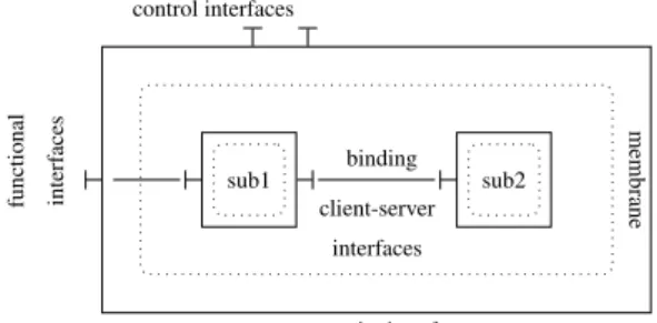
The Fractal Component Model (cf. Figure 1) includes the ba-sic architectural concepts of hierarchical composition of com-ponents, required (client) and provided (server) interfaces, and bindings connecting components’ interfaces. The model was also designed with separation of concerns design principle in mind. The main idea is to decouple a component implementa-tion into two parts: content and membrane. The content man-ages the functional concerns and its operations are exposed by a set of functional interfaces. The membrane embodies a set of controllersthat takes care of the non-functional concerns. Con-trol interfacesare access points to membrane controllers, which in turn implement some introspection and/or intercession capa-bilities, making Fractal a distinguished Component Model con-cerning the support for dynamic reconfiguration. Examples of controllers are the life-cycle, which controls the component’s behavioural phases (e.g., starting, started, stopping, stopped, etc.); and the binding controllers, to dynamically establish or break bindings between component’s interface and its environ-ment. sub1 sub2 control interfaces functional interf aces composite interface membrane binding client-server interfaces
Figure 1: Fractal Architectural Concepts.
In short, component-based architectures, and especially the ones equipped with reflection capabilities like Fractal, have ca-pabilities that are particularly interesting and applicable in the domain of self-adaptive software systems. This is generally achieved by first using ADLs, to define initial architectural con-figurations, from which, by relying on introspection and recon-figuration mechanisms [2] or languages [5], one can add or re-move elements at runtime in response to environment changes, while mitigating the interferences on their execution.
Software components can be controlled according to
moni-I W A a=false a=false a=true r ∧ ¬c r ∧ c/s e c/s lifecycle(r,c,e)=a,s
Figure 2: Graphical Representation of Component Lifecycle.
tored events, the current state, available configurations and in-variant properties [17]. This reactive nature of software com-ponents makes reactive systems and languages a very suited to support design of such control behaviour.
2.2. Reactive Systems and Languages
Reactive Languages have been proposed to describe systems that at each reaction perform a step taking input flows, com-puting transitions, updating states, triggering actions, emitting output flows [18]. Their definition is often based on Finite State Automata (FSA), which constitute the basic formalism for rep-resenting behaviours, as is the case of StateCharts [19] and of synchronous languages [20].
2.2.1. Heptagon
Heptagon/BZR [13] is an example of such languages. It al-lows the definition of reactive systems by means of generalized Moore machines, i.e., with mixed synchronous data-flow equa-tions and automata [21]. An Heptagon program is modularly structured with a set of nodes. Each node corresponds to a re-active behaviour that takes as input and produces as output a set of stream values. The body of a node consists of a set of declarations that take the form of either automata or equations. The equations determine the values for each output, in terms of expressions on inputs’ instantaneous values or other flows values.
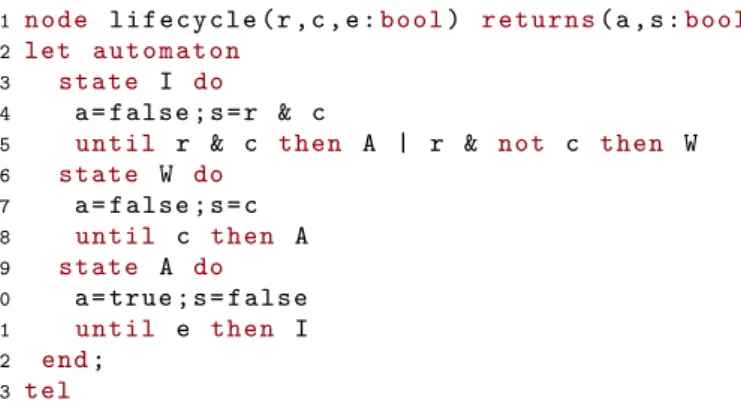
Figure 2 and Listing 1 show an Heptagon program respec-tively in graphical and textual representations. The program describes the control of a component lifecycle that can be in ei-ther idle (I), waiting (W) or active (A) states. The program takes as input three boolean variables: r, which represents a request signal for the component; c, which represents an external con-dition (to be used later on as controllable variable); and e, to represent an end signal. It produces as output two boolean val-ues, one that indicates whether the component is active (a) the another indicating a start action (s). When in the initial state, upon a request signal (i.e., when r is true), the automaton leads to either waiting or active states, depending whether the condi-tion c holds. If it does not, it goes first to the waiting state and then to active when c becomes true. All the incoming transi-tions arriving at active state triggers the start action (s). From active state, it goes back to idle state upon an end signal.
1 n o d e l i f e c y c l e ( r , c , e :b o o l) r e t u r n s( a , s :b o o l)
2 let a u t o m a t o n
3 s t a t e I do
4 a = f a l s e ; s = r & c
5 u n t i l r & c t he n A | r & not c t h e n W
6 s t a t e W do 7 a = f a l s e ; s = c 8 u n t i l c t h e n A 9 s t a t e A do 10 a = t r u e ; s = f a l s e 11 u n t i l e t h e n I 12 end; 13 tel
One important characteristic of Heptagon/BZR is the support for hierarchical and parallel automata composition. Figure 3 il-lustrates an example of hierarchical composition, in which a single state super-automaton embodies the lifecycle automaton of Figure 2. It has a self-transition that results in the resetting of the sub-automaton (i.e., lifecycle) at every occurrence of sig-nal b. A stream of input/output values for this automaton can be seen in Table 1. In particular, we can see at step 9, the re-setting of the sub-automaton, which brings it from state active back to idle (at step 10), without any explicit transition. List-ing 2 illustrates the parallel composition of two instances of the delayablenode (and the operator ’;’). They run in parallel, in a synchronous way, meaning that one global step corresponds to one local step for every node.
lifecycle b reset(b,r,c,e)=a,s n o d e r e s e t ( b , r , c , e :b o o l) r e t u r n s( a , s :b o o l) let a u t o m a t o n s t a t e H do ( a , s ) = l i f e c y c l e ( r , c , e ) u n t i l b t h e n H end; tel
Figure 3: Example of Hierarchical Composition.
Table 1: Execution of the Hierarchical Composition.
step # 1 2 3 4 5 6 7 8 9 10 . . . b 0 0 0 0 0 0 0 0 1 0 . . . r 0 1 0 0 0 0 1 0 0 0 . . . c 0 0 1 0 0 0 1 0 0 0 . . . e 0 0 0 0 1 0 0 0 0 0 . . . a 0 0 0 1 1 0 0 1 1 0 . . . s 0 0 1 0 0 0 1 0 0 0 . . .
2.2.2. Contracts and Discrete Controller Synthesis
BZR is an extension of Heptagon with specific constructs for Discrete Controller Synthesis (DCS). That makes Hep-tagon/BZR distinguishable since its compilation may involve formal tools for DCS purposes. A DCS consists in automati-cally generating a controller capable of acting on the original program to control input variables such that a given temporal property is enforced. In Heptagon/BZR, DCS is achieved by
associating a contract to a node. A contract is itself a pro-gram with two outputs: eA, an assumption on the node
envi-ronment; and eG, a property to be enforced by the node. A set
{c1, c2, . . . , cq} of local controllable variables is used for
ensur-ing this objective. Puttensur-ing it differently, the contract means that the node will be controlled by giving values to {c1, . . . , cq} such
that given any input flow satisfying assumption eA, the output
will always satisfy goal eG. When a contract has no
control-lable variables specified, a verification that eGis satisfied in the
reachable state space is performed by model checking, even if no controller is generated.
Listing 2: Example of Contract in Heptagon/BZR.
1 n o d e t w o c o m p o n e n t s ( r1 , r2 , e1 , e2 :b o o l) r e t u r n s ( a1 , a2 , s1 , s2 :b o o l) 2 c o n t r a c t 3 a s s u m e t r u e 4 e n f o r c e not( a1 and a2 ) 5 w i t h ( c1 , c2 ) 6 let 7 ( a1 , s1 ) = l i f e c y c l e ( r1 , c1 , e1 ) ; 8 ( a2 , s2 ) = l i f e c y c l e ( r2 , c2 , e2 ) 9 tel
Listing 2 shows an example of contract on a node enclosing a parallel composition of two instances of lifecycle (cf. Fig-ure 2). It is composed of three blocks. The assume block (line 3), which in this case, states that there is no assumption on the environment (i.e., eA = true). The enforce block (line 4)
describes the control objective : eG= ¬(a1 ∧ a2), meaning that
both components are mutually exclusive, i.e., they cannot be active at the same time. Lastly, the with block (line 5) defines two controllable variables that are used within the node (line 7). In practice they will be given values such that variables a1 and a2 are never both true at the same instant.
2.2.3. Compilation and code generation
The Heptagon/BZR compilation chain is as follows: from source code, the Heptagon/BZR compiler produces as output a sequential code in a general-purpose programming language (e.g., Java or C) implementing the control logic, in the form of a step function to be called at each decision in the autonomic loop. At the same time, if the code provided as input contains some contracts, the compiler will also generate a intermediary code that will be given as input to the model checker (e.g., Si-gali or Reax), which will, in turn, perform the DCS and produce as output an Heptagon/BZR code corresponding to the gener-ated controller. The latter is then compiled again so as to have an executable code also for the generated controller.
3. Ctrl-F Language
This section presents Ctrl-F, our domain specific language (DSL) for describing control policies. Section 3.1 introduces the Znn.com scenario that will be used throughout the arti-cle to illustre the concepts introduced with Ctrl-F. Section 3.2 presents the core concepts of Ctrl-F. Section 3.3 and 3.4 define the notions of behaviour and policy that are specific to Ctrl-F.
3.1. Example Application
Znn.com [14] is an experimental platform for self-adaptive applications, which mimics a news website. As in any web application, Znn.com follows a typical client-server n-tiers ar-chitecture, meaning that it relies on a load balancer to redirect requests from clients to a pool of replicated servers. The num-ber of active servers can be regulated in order to maintain a good trade-off between response time and resource utilization. Hence, the objective of Znn.com is to provide news content to its clients/visitors within a reasonable response time, while keeping costs as low as possible and/or under control (i.e., con-strained by a certain budget).
There might be times where only the pool of servers is not enough to provide the desired Quality of Service (QoS). For in-stance, in order to face workload spikes, Znn.com can be forced to degrade the content fidelity so as to require fewer resources to provide the same level of QoS. For this purpose, Znn.com servers are able to deliver news contents in three different ways: (i) with high quality images, (ii) with low quality images, and (iii) with only text. Hence, content fidelity can be seen as an-other criteria. In summary, the objectives are as follows:
• Keep the performance (in terms of response time) as high as possible;
• Keep content fidelity as high as possible or above a certain threshold;
• Keep the number of active servers as low as possible or under a certain threshold.
In order to achieve them, we may tune: • The number of active servers and • The content fidelity of each server. 3.2. Core Concepts
Ctrl-F is our proposal for a architecture description language with high-level constructs for describing reconfiguration be-haviours and policies to be enforced all along the execution of the target system.
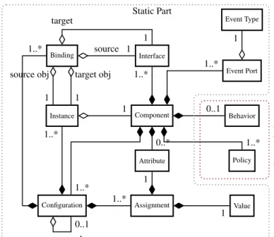
As depicted in Figure 4, the abstract syntax of Ctrl-F can be divided into two parts: a static one, which is related to the com-mon architectural concepts (components, connections, configu-rations, etc.); and a dynamic one, which refers to reconfigura-tion behaviours and policies that must be enforced regardless of the configuration.
The static part of Ctrl-F provides the same core concepts as many existing ADLs (e.g., Fractal [2], Acme [16]). A compo-nentconsists of a set of interfaces, a set of event ports, a set of attributesand a set of configurations. Interfaces define how a component can interact with other components. They are used to express a required functionality (client interface) that may be provided by another component and/or to express a provided functionally (server interface) that might be used by other com-ponents. Event Ports describe the events, of the given Event Type, a component is able to emit (port out) and/or listen to
Component Interface Binding Instance Behavior Policy Attribute
Configuration Assignment Value
Event Port Event Type 1..* source 1 target 1 source obj 1 target obj 1 1 1..* 1..* 1..* 1..* extends 0..1 1 1 0..* 0..1 1..* 1 1..* Static Part Dynamic P art
Figure 4: Language Abstract Syntax.
(port in). A configuration is defined as a set of instances of components, a set of bindings connecting server and client in-terfacesof those instances (i.e., an assembly), and/or a set of attributeassignments to values.
The dynamic part consists of a behaviour and a set of poli-ciesthat can be defined for each component. A behaviour takes the form of orders and conditions (w.r.t. events and attribute values) under which transitions between configurations (recon-figurations) take place. The policies are high-level objectives /-constraints, which may imply the inhibition of some of those transitions.
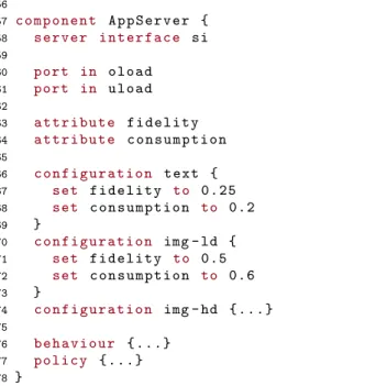
The Znn.com example application of Section 3.1 can be mod-eled as a hierarchical composition of four components: Main, Znn, LoadBalancer, and AppServer. These components are in-stantiated according to execution conditions, the system cur-rent state (architectural composition), adaptation behaviours and policies defined within each component. Listing 3 shows the textual definition of such components with the static part of Ctrl-F. In addition, to better illustrate the Ctrl-F concepts, the graphical representation of those components is depicted in Figures 5, 6 and 7, where the vertical bars, squares, triangles, and upside-down triangles correspond to interfaces, attributes, port in and out, respectively.
The Main component (lines 1-14) encompasses two in-stances of Znn, namely soccer and politics within a single con-figuration (lines 7 and 8). The server interfaces of both in-stances (lines 9 and 10), which provides access to news ser-vices, are bound to the server interfaces of the Main component (lines 3 and 4) in order for them to be accessed from outside. A policy to be enforced is defined (line 13) and discussed in Section 3.4.
Component Znn (lines 16-33) consists of one provided inter-face (line 18) through which news can be requested. The
com-soccer:Znn
consumption fidelity
politics:Znn
consumption fidelity
main
Figure 5: Graphical Representation of Main component.
ponent listens to events of types oload (overload) and uload (underload) (lines 20 and 21), which are emitted by other com-ponents. In addition, the component also defines two attributes: consumption (line 23), which is used to express the level of consumption (in terms of percentage of CPU) incurred by the component execution; and fidelity (line 24), which expresses the content fidelity level of the component.
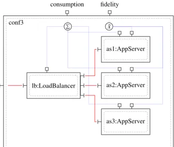
Three configurations are defined for Znn component: conf1, conf2 and conf3. conf1 (lines 26-33) consists of one instance of each LoadBalancer and AppServer (lines 27 and 28); one binding to connect them (line 29), another binding to expose the server interface of the LoadBalancer component as a server interface of the Znn component (line 30), and the attribute as-signments (lines 31 and 32). The attribute fidelity corresponds to the counterpart of instance as1, whereas for the consumption it corresponds to the sum of the consumptions of instances as1 and lb. conf2 (lines 34-39) extends conf1 by adding one more instance of AppServer, binding it to the LoadBalancer and re-defining the attribute values with respect to the just-added com-ponent instance (as2).
In that case, the attribute fidelity values the average of the counterparts of instances as1 and as2 (line 37), whereas for the consumption the same logics is applied so the consumption of the just-added instance is incorporated to the sum expres-sion (line 38). The definition of configuration conf3 follows the same idea: it extends conf2 by adding a new instance of AppServer, binding it and redefining the attribute values.
Listing 3: Architectural Description of Components Main, Znn, Load Balancer and AppServer in Ctrl-F. 1 c o m p o n e n t M a i n { 2 3 s e r v e r i n t e r f a c e sis 4 s e r v e r i n t e r f a c e sip 5 6 c o n f i g u r a t i o n m a i n { 7 s o c c e r : Znn 8 p o l i t i c s : Znn 9 b i n d sis to s o c c e r . si 10 b i n d sip to p o l i t i c s . si 11 } 12 13 p o l i c y { . . . } 14 } 15 16 c o m p o n e n t Znn { 17 18 s e r v e r i n t e r f a c e si lb:LoadBalancer as2:AppServer as1:AppServer as3:AppServer conf3 consumption fidelity P ¯x
Figure 6: Graphical Representation of Znn component.
19 20 p o r t in o l o a d 21 p o r t in u l o a d 22 23 a t t r i b u t e c o n s u m p t i o n 24 a t t r i b u t e f i d e l i t y 25 26 c o n f i g u r a t i o n c o n f 1 { 27 lb : L o a d B a l a n c e r 28 as1 : A p p S e r v e r 29 b i n d lb . ci1 to as1 . si 30 b i n d lb . si to si 31 set f i d e l i t y to as1 . f i d e l i t y
32 set c o n s u m p t i o n to sum( as1 . c o n s u m p t i o n , lb . c o n s u m p t i o n )
33 }
34 c o n f i g u r a t i o n c o n f 2 e x t e n d s c o n f 1 {
35 as2 : A p p S e r v e r
36 b i n d lb . ci2 to as2 . si
37 set f i d e l i t y to avg( as1 . f i d e l i t y , as2 . f i d e l i t y )
38 set c o n s u m p t i o n to sum( as1 . c o n s u m p t i o n , as2 . c o n s u m p t i o n , lb . c o n s u m p t i o n ) 39 } 40 41 c o n f i g u r a t i o n c o n f 3 e x t e n d s c o n f 2 { . . . } 42 43 b e h a v i o u r { . . . } 44 p o l i c y { . . . } 45 } 46 47 c o m p o n e n t L o a d B a l a n c e r { 48 s e r v e r i n t e r f a c e si 49 c l i e n t i n t e r f a c e ci1 , ci2 , c3 50 51 p o r t out o l o a d 52 p o r t out u l o a d 53 54 a t t r i b u t e c o n s u m p t i o n = 0 . 2 55 }
56 57 c o m p o n e n t A p p S e r v e r { 58 s e r v e r i n t e r f a c e si 59 60 p o r t in o l o a d 61 p o r t in u l o a d 62 63 a t t r i b u t e f i d e l i t y 64 a t t r i b u t e c o n s u m p t i o n 65 66 c o n f i g u r a t i o n t e x t { 67 set f i d e l i t y to 0 . 2 5 68 set c o n s u m p t i o n to 0.2 69 } 70 c o n f i g u r a t i o n img - ld { 71 set f i d e l i t y to 0.5 72 set c o n s u m p t i o n to 0.6 73 } 74 c o n f i g u r a t i o n img - hd { . . . } 75 76 b e h a v i o u r { . . . } 77 p o l i c y { . . . } 78 }
Component LoadBalancer (lines 47-55) consists of four in-terfaces: one provided (line 48), through which the news are provided; and the others required (line 49), through which the load balancer delegates each request for balancing purposes. We assume that this component is able to detect overload and underload situations (in terms of number of requests per sec-ond) and in order for this information to be useful for other components we define two event ports that are used to emit events of type oload and uload (lines 51 and 52). Like for component Znn, attribute consumption (line 54) specifies the level of consumption of the component (e.g., 0.2 to express 20% of CPU consumption). As there is no explicit definition of configurations, LoadBalancer is implicitly treated as a single-configuration component.
Lastly, the atomic component AppServer (lines 57-78) has only one interface (line 58) and listens to events of type oload and uload (lines 60 and 61). It has also two attributes: fi-delity and consumption (lines 63 and 64), just like component Znn. Three configurations corresponding to each level of fi-delity (lines 66-69, 70-73 and 74) are defined, and the attributes are valuated according to the configuration in question, i.e., the higher the fidelity the higher the consumption.
3.3. Behaviours
A particular characteristic of Ctrl-F is the capability to com-prehensively describe behaviours in component-based applica-tions. We mean by behaviour the process in which architectural elements are changed. More precisely, it refers to the order and conditions under which configurations within a component take place.
Behaviours in Ctrl-F are defined with the aid of a high-level imperative language. It consists of a set of behavioural state-ments (sub-behaviours) that can be composed together so as to provide more complex behaviours in terms of sequences of con-figurations. In this context, a configuration is considered as an atomic behaviour, i.e., a behaviour that cannot be decomposed
LoadBalancer cons.=0.20 oload uload (a) AppServer img-ld cons.=0.6 fidel.=0.5 (b) AppServer text cons.=0.20 fidel.=0.25 oload uload AppServer img-hd cons.=1 fidel.=0.75
Figure 7: Graphical Representation of (a) Load Balancer and (b) App Server components.
Table 2: Summary of Behaviour Statements.
Statement Description B when e1 do B1,
... , While executing B when ei
exe-cute Bi
en do Bn end
case c1 then B1,
... , Execute Biif ciholds, otherwise
execute Be
cn then Bn
else Be end
B1| B2 Execute either B1or B2
B1|| B2 Execute B1and B2in parallel
do B every e Execute B and re-execute it at
every occurrence of e
into other sub-behaviours. A reconfiguration occurs when the current configuration is terminated and the next one is started. We assume that configurations do not have the capability to di-rectly terminate or start themselves, meaning that they are ex-plicitly requested or ended by behaviour statements according to the defined events and policies. Nevertheless, as components are capable to emit events, it would not be unreasonable to de-fine components whose objective is to emit events in order to force a desired behaviour.
3.3.1. Statements
Table 2 summarizes the behaviour statements of the Ctrl-F behavioural language. During the execution of a given be-haviour B, the when-do statement states that when a given event of type eioccurs the configuration(s) that compose(s) B should
be terminated and that (those) of the corresponding behaviour Biare started.
The case-then statement is quite similar to when-do. The dif-ference resides mainly in the fact that a given behaviour Bi is
executed if the corresponding condition ci holds (e.g.,
a given event to occur. In addition, if none of the conditions holds (c1∧... ∧ cn = 0), a default behaviour (Be) is executed,
which forces the compiler to choose at least one behaviour. The parallelstatement states that two behaviours are executed at the same time, i.e., at a certain point, there must be two independent branches of behaviour executing in parallel. This construct is also useful in the context of atomic components like AppServer, where we can, for instance, define configurations composed of orthogonal attributes like fidelity and font size/color (e.g., text || font-huge).
The alternative statement allows to describe choice points among configurations or among more elaborated sequential be-haviour statements. They are left free in local specifications and will be resolved in upper level assemblies, in such a way as to satisfy the stated policies, by controlling these choice points appropriately. Finally, the do-every statement allows for execu-tion of a behaviour B and re-execuexecu-tion of it at every occurrence of an event of type e. It is noteworthy that behaviour B is pre-empted every time an event of type e occurs. In other words, the configuration(s) currently activated in B is (are) terminated, and the very first one(s) in B is (are) started.
3.3.2. Example in Znn.com
We now illustrate the use of the statements we have in-troduced to express adaptation behaviours for components AppServer and Znn of the Znn.com case study. The expected behaviour for component AppServer is to pick one of its three configurations (text, img-ld or img-hd) at every occurrence of events of type oload or uload. To that end, as it can be seen in Listing 4, the behaviour can be decomposed in a do-every statement, which is, in turn, composed of an alternative one. It is important to mention that the decision on one or other con-figuration must be taken at runtime according to input variables (e.g., income events) and the stated policies, that is, there must be a control mechanism for reconfigurations that enforces those policies. We come back to this subject in Section 4.
Listing 4: AppServer’s Behaviour. 1 c o m p o n e n t A p p S e r v e r { ... 2 b e h a v i o u r { 3 do 4 t e x t | img - ld | img - hd 5 e v e r y ( o l o a d or u l o a d ) 6 } 7 }
Regarding component Znn, the expected behaviour is to start with the minimum number of AppServer instances (configu-ration conf1) and add one more instance, i.e., leading to con-figuration conf2, upon an event of type (oload). From conf2, one more instance must be added, upon an event of type oload leading to configuration conf3. Alternatively, upon an event of type uload, one instance of AppServer must be removed, which will lead the application back to configuration conf1. Similarly, from configuration conf3, upon a uload event, another instance must be removed, which leads the application to conf2. It is notorious that this behaviour can be easily expressed by an automaton, with three states (one per configuration) and four
transitions (triggered upon the occurrence of oload and uload). However, Ctrl-F is designed to tackle the adaptation control problem in a higher level, i.e., with process-like statements over configurations.
For these reasons, we describe the behaviour with two em-bedded do-every statements, which in turn comprise each a when-dostatement, as shown in Listing 5 (lines 6-14 and 8-12). We also define two auxiliary configurations: emitter1 (line 2) and emitter2 (line 3), which extend respectively configurations conf2and conf3, with an instance of a pre-defined component Emitter. This component does nothing but emit a given event (e.g., e1 and e2) so as to force a loop step and thus go back to the beginning of the when-do statements. The main do-every state-ment (lines 6-14) performs a when-do statestate-ment (lines 7-13) at every occurrence of an event of type e1. In practice, the firing of this event allows going back to conf1 regardless of the current configuration being executed. conf1 is executed until the oc-currence of an event of type oload (line 7), then the innermost do-everystatement is executed (lines 8-12), which in turn, just like the other one, executes another when-do statement (lines 9-11) and repeats it at every occurrence of an event of type e2. Again, this structure allows the application to go back to con-figuration conf2. Concon-figuration conf2 is executed until an event of type either oload or uload occurs. For the former case (line 9), another when-do statement takes place, whereas for the lat-ter (line 10) configuration emitlat-ter1 is the one that takes place. Essentially, at this point, an instance of component Emitter is deployed along with conf2, since emitter1 extends conf2. As a consequence, this instance fires an event of type e1, which forces the application to go back to conf1. The innermost when-dostatement (line 9) consists in executing conf3 until an event of type uload occurs, then configuration emitter2 takes place, which makes an event of type e2 be fired in order to force going back to conf2.
It is important to notice that this kind of construction allows to achieve the desired behaviour while sticking to the language design principles, that is, high-level process-like constructs and configurations. It also should be remarked that while in Listing 5, we present an imperative approach to forcibly increase the number of AppServer instances upon uload and oload events, in Listing 4 we let the compiler choose the most suitable fidelity level according to the runtime events and conditions. Although there is no straightforward guideline, an imperative approach is clearly more suitable when the solution is more sequential and delimited, whereas as the architecture gets bigger, in terms of configurations, and less sequential, then a declarative definition becomes more interesting.
3.4. Policies
Policies are expressed with high-level constructs for con-straints on configurations, either temporal or on attribute val-ues. In general, they define a subset of all possible global con-figurations, where the system should remain invariant: this will be achieved by using the choice points in order to control the reconfigurations. An intuitive example is that two component instances in parallel branches might have each several possi-ble configurations, and some of them have to be kept
exclu-Listing 5: Znn’s Behaviour. 1 c o m p o n e n t Znn { . . . 2 c o n f i g u r a t i o n e m i t t e r 1 e x t e n d s c o n f 2 { e : E m i t t e r } 3 c o n f i g u r a t i o n e m i t t e r 2 e x t e n d s c o n f 3 { e : E m i t t e r } 4 5 b e h a v i o u r { 6 do 7 c o n f 1 w h e n o l o a d do 8 do 9 c o n f 2 w h e n o l o a d do ( c o n f 3 w h e n u l o a d do e m i t t e r 2 end) , 10 u l o a d do e m i t t e r 1 11 end 12 e v e r y e2 13 end 14 e v e r y e1 15 } 16 }
sive. This exclusion can be enforced by choosing the appropri-ate configurations when starting the components.
3.4.1. Constraints/Optimization on Attributes
This kind of constraints are predicates and/or primitives of optimization objectives (i.e., maximize or minimize) on com-ponent attributes. Listing 6 illustrates some constraints and op-timization on component attributes. The first two policies state that the overall fidelity for component instance soccer should be greater or equal to 0.75, whereas that of instance politics should be maximized. Putting it differently, instance soccer must never have its content fidelity degraded, which means that it will have always priority over politics. The third policy states that the overall consumption should not exceed 5, which can be inter-preted as a constraint on the physical resource capacity, e.g., the number of available machines or processing units.
Listing 6: Example of Constraint and Optimization on Attributes. 1 c o m p o n e n t M a i n { ... 2 p o l i c y { s o c c e r . f i d e l i t y >= 0 . 7 5 } 3 p o l i c y { m a x i m i z e p o l i t i c s . f i d e l i t y } 4 p o l i c y { ( s o c c e r . c o n s u m p t i o n + 5 p o l i t i c s . c o n s u m p t i o n ) <= 5 } 6 } 3.4.2. Temporal Constraints
Temporal constraints are high-level constructs that take the form of predicates on the order of configurations. These con-structs might be very helpful when there are many possible re-configuration paths (by either parallel or alternative composi-tion, for instance), in which case the manual specification of such constrained behaviour may become a very difficult task.
To specify these constraints, Ctrl-F provides four constructs, as follows:
• con f1 precedes con f2: con f1 must take place right
be-fore con f2. It does not mean that it is the only one, but
it should be among the configurations taking place right before con f2.
• con f1 succeeds con f2: con f1must take place right after
con f2. Like in the precedes constraint, it does not mean
that it is the only one to take place right after con f2.
• con f1 during con f2: con f1 must take place along with
con f2.
• con f1 between (con f2, con f3): once con f2 is started,
con f1 cannot be started and con f3, in turn, cannot be
started before con f2terminates.
Listing 7 shows an example of how to apply temporal con-straints, in which it is stated that configuration img-ld comes right after the termination of either configuration text or con-figuration img-ld. In this example, this policy avoids abrupt changes on the content fidelity, such as going directly from text to image high definition or the other way around. Again, it does not mean that no other configuration can take place along with img-ld, but the alternative statement in the behaviour described in Listing 4 leads us to conclude that only img-ld must take place right after either text or img-hd has been terminated.
Listing 7: Example of Temporal Constraint. 1 c o m p o n e n t A p p S e r v e r { ... 2 p o l i c y { img - ld s u c c e e d s t e x t } 3 p o l i c y { img - ld s u c c e e d s img - hd } 4 } 4. Heptagon/BZR Model 4.1. Approach Overview
Our approach consists in seamlessly conceiving autonomic component-based applications by relying on a high-level be-havioural description. The principle is to have an autonomic manager (AM) embodying a feedback control loop within each component. The manager takes decisions in response to oc-curred events, while taking into consideration the current/past configurations, a behavioural program, and determining as re-sult which configurations have to be terminated and which ones
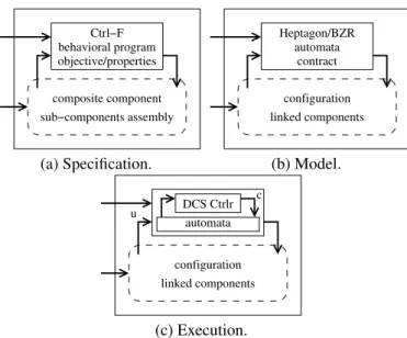
Ctrl−F composite component sub−components assembly objective/properties behavioral program (a) Specification. linked components contract automata Heptagon/BZR configuration (b) Model. c configuration linked components automata DCS Ctrlr u (c) Execution.
Figure 8: Approach Overview.
have to be started. We rely on Ctrl-F to specify: (i) behaviours in a process-like manner (in terms of sequences, alternative/-conditional/parallel branches and loops of configurations); and (ii) policies, which take the form of properties that have to be kept invariant regardless of the configuration, as depicted in Figure 8(a).
The behavioural program defined by Ctrl-F provides the AM an extra level of knowledge on the possible futures of the com-ponent configuration: that is, it enables the AM to explore the space of reachable configurations so as to avoid branches that may lead, in the future, to configurations violating the stated policies. To that end, we provide a set of translation schemes allowing for the automatic translation from a Ctrl-F descrip-tion to the reactive language Heptagon/BZR and thereby ben-efiting from DCS. an Heptagon/BZR automaton and contract corresponding to the behavioural program and policies will be associated to each component under control, as can be seen in Figure 8(b). The Heptagon/BZR program, once equipped with contracts, allows us to either perform formal verification on the behavioural program with respect to the policies; and/or to ob-tain, via DCS, a correct-by-construction controller (cf. Figure 8 (c)). That is to say that the generated controller will be ca-pable of controlling the automaton that models the component behaviour so as to prevent it going in branches leading to bad states (i.e., configurations that violate the policies). This pro-cess, from the Ctrl-F description to the Heptagon/BZR transla-tion, is detailed next.
4.2. General FSA Model Structure
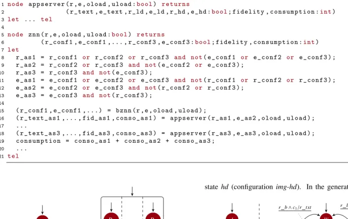
The component is the core of Ctrl-F description and can be modeled as an Heptagon/BZR node, as shown in Figure 9. The node takes as input external request (r) and end notification (e) signals, and a set of events {v1, . . . , vk}, which corresponds
to the event types the component in question (comp) listens to. As output, it produces a set of request (resp. end) signals {r1, . . . , rm} (resp. {e1, . . . , em}) for each configuration con fi, for
i ∈ [1, m], defined within the concerned component. In addi-tion, it also returns a set of weights {w1, . . . , wl}, for the attribute
valuation for each attribute in the component. The main node (comp in Figure 9) may contain a contract in which a set of con-trollable variables {c1, . . . , cq} (in the case there is any choice
point such as a behaviour with an alternative statement) and the reference to the set of stated policies ({p1, . . . , pt}) in order for
them to be enforced by the controller resulting from the DCS. The details on how policies are translated are given in Section 4.4.
Idle conf1 conf2 ...
r/r1 r/r2,e1 r/r3,e2 bcomp(r,e,v1, . . . ,vk,c1, . . . ,cq)=(r1,e1, . . . ,rm,em,w1, . . . ,wl) with c1, . . . ,cq enforce p1∧. . . ∧pt rsub1= (r1∨. . . ∨rm) ∧ ¬(e1∨. . . ∨em) esub1 = (e1∨. . . ∨em) ∧ ¬(r1∨. . . ∨rm) ...
sub1(rsub1,esub1, . . .)=(rsub11 ,esub11 , . . . ,wsub11 , . . .)
.. . rsubn= (r 1∨. . . ∨rm) ∧ ¬(e1∨. . . ∨em) esubn= (e 1∨. . . ∨em) ∧ ¬(r1∨. . . ∨rm) ...
subn(rsubn,esubn, . . .)=(rsubn1 ,esubn1 , . . . ,wsubn1 , . . .)
comp(r,e,v1, . . . ,vk)=(r1,e1, . . . ,rm,em,w1, . . . ,wl)
Figure 9: Translation Scheme Overview.
Component behaviours are modeled as a sub-node (bcomp in Figure 9), which consists of an automaton describing the or-der and conditions unor-der which configurations take place. For this purpose, it gets as input the same request (r), end (e) and event ({v1, . . . , vk}) signals of the main node. As a result of the
reaction to those signals, it produces the same signals for re-questing ({r1, . . . , rm}) and ending ({e1, . . . , em}) configurations
as the weights ({w1, . . . , wl}) corresponding to the attributes
val-uation in the current state (configuration) of the behaviour. We provide further details on the translation of behavioural state-ments in Section 4.3. Lastly, there might also be some other sub-nodes ({sub1, ..., subn}) referring to components
instanti-ated within the concerned component, i.e., comp. They have interfaces and contents which are structurally identical to those of the main node. That is to say, that sub-nodes may have, in turn, a contract, a behaviour sub-node and a sub-node per component instance defined inside it. It is noteworthy that the request (rsubi) and end (esubi) signals for a sub-component
subi ∈ {sub1, . . . , subn} are defined as equations of request and
end signals. {r1, . . . , rm} and {e1, . . . , em} are respectively the
sets of request and end signals for the configurations con f1, . . . ,
con fm to which component subi belongs. That means that a
sub-component subi will be requested if any configuration it
is terminated ¬(e1∨. . . ∨ em), which avoids emitting a request
signal for an already active component. The same applies for its termination.
Listing 8 shows an excerpt of Heptagon/BZR model for com-ponents Znn (lines 5-21) and AppServer (lines 1-3). For node appserver, besides the request and end signals, it gets as inputs the events of type oload and uload (line 1). As output (line 2), it produces request and end signals for configurations text (r text and e text), img-ld (r ld and e ld) and img-hd (r hd and e hd), apart from weights, i.e., attribute valuations (fidelity and consumption). Node znn has a very similar interface as appserver, except that it produces as output request and end signals for configurations conf1 (r conf1 and e -conf1), conf2 (r conf2 and e conf2) and conf3 (r conf3 and e conf3). Regarding its body (lines 8-20), znn comprises one instance of the node that models the behaviour (bznn, line 15) and three instances of node appserver (lines 16-18). The request and end signals for these instances can be derived from the request and end signals for configurations (lines 8-13). At last, attributes are values based on the values of attributes of the instances of node appserver (line 19).
4.3. Behaviours
For each program in Ctrl-F, we need to construct a FSA model, in Heptagon/BZR, of all its possible behaviours. We translate each behaviour statement defined inside another be-haviour as sub-automaton, hierarchically decomposing the whole behaviour into smaller pieces, down to a configuration. 4.3.1. The top-most behaviour
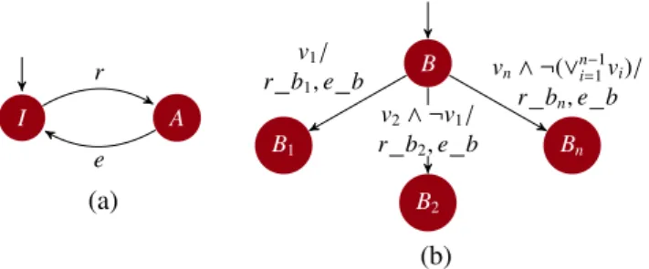
The top-most automaton i.e., the automaton modeling the whole behaviour consists of a two-state model, as depicted in Figure 10 (a). The automaton is in state Idle when the com-ponent does not take part in the current configuration. Upon a request signal (r), it goes to Active state, from where it can go back again to Idle state again upon an end signal (e). Active state accommodates a behaviour statement itself, which is itself modeled as a sub-automaton of state A.
I A r e (a) B B1 B2 Bn v1/ r b1, e b v2∧ ¬v1/ r b2, e b vn∧ ¬(∨n−1i=1vi)/ r bn, e b (b)
Figure 10: FSA Modeling: (a) Lifecycle; (b) When-Do.
4.3.2. Statements
The automaton that models the statement when-do (cf. Fig-ure 10(b)) consists of an initial state B corresponding to the first behaviour statement to be executed. The automaton goes to state Bi(corresponding to the execution of the next behaviour)
upon a signal (event) viwhile producing signals for requesting
the initiation of to the next behaviour (r bi) and the
termina-tion (e b) the current one (for 1 ≤ i ≤ n). It is important to notice that upon two events at the same time, a priority is given according to the order behaviours are declared. For instance, if v1and v2 triggers, respectively, behaviours B1and B2, then B1
will be triggered if declared before B2.
Both behaviour statements case and alternative can be mod-eled by the automaton shown in Figure 11. As the sub-behaviour statements should be executed at the very first in-stant upon the request of the case or alternative statement, the automaton must be composed in parallel with the automaton modeling the main behaviour (inside node bcomp, in Figure 9). Hence, a case or an alternative statement is modeled as a simple state inside the (super) automaton in the hierarchy that models the main behaviour. Upon a request to those statements (signal r), the main automaton emits a request signal r0that will trigger
a transition from state W to the next state (B1or B2) according
to variable c. Then it can go either to another behaviour, if an-other r0is emitted and c states so; or back to W if an end signal
(e0) is emitted. W B1 B2 r 0∧ c/r b1 r0∧ ¬ c/r b 2 e0∧ r0∧ c/r b1 e0∧ r0∧ ¬c/r b2 e0∧ ¬r0/ e b2 e0∧ r0∧ ¬c/ e b1, r b2 e0∧ r0∧ c/ e b2, r b1 e0∧ ¬r0/ e b1
...
B...
r/r0 e/e0 Main Behaviour Case/AlternativeFigure 11: Parallel Composition of Automata Modeling the Main Behaviour and the Case/Alternative Statement.
There are two differences between the use of this automa-ton for a case or an alternative statement. First, for the case statement, several (i.e., more than two) branches are allowed, so there might be more states (B1, B2, . . . , Bn) referring to each
branch as well as their corresponding conditions c1, c2, ..., cn,
which was omitted here for readability reasons. Second, for the alternativestatement, the conditions ci will be considered as
controllablevariables in Heptagon/BZR. Thus, a DCS should be performed to guarantee that the stated policies are not vio-lated.
The automaton model for the do-every statement is shown in Figure 12(a). It consists of a single-state automaton, which means that it starts by directly executing statement B. It has a self-transition at every occurrence of signal s, while emitting end (e b) and request (r b) signals, that is, statement B is re-executed at every occurrence of event s. Finally, Figure 12(b) presents the model for the Parallel statement: simply in the parallel composition of sub-automata.
Listing 8: Heptagon/BZR code for Znn and AppServer. 1 n o d e a p p s e r v e r ( r , e , oload , u l o a d :b o o l) r e t u r n s
2 ( r_text , e_text , r_ld , e_ld , r_hd , e _ h d :b o o l; f i d e l i t y , c o n s u m p t i o n :int)
3 let ... tel
4
5 n o d e znn ( r , e , oload , u l o a d :b o o l) r e t u r n s
6 ( r_conf1 , e_conf1 ,... , r_conf3 , e _ c o n f 3 :b o o l; f i d e l i t y , c o n s u m p t i o n :int)
7 let 8 r _ a s 1 = r _ c o n f 1 or r _ c o n f 2 or r _ c o n f 3 and not( e _ c o n f 1 or e _ c o n f 2 or e _ c o n f 3 ) ; 9 r _ a s 2 = r _ c o n f 2 or r _ c o n f 3 and not( e _ c o n f 2 or e _ c o n f 3 ) ; 10 r _ a s 3 = r _ c o n f 3 and not( e _ c o n f 3 ) ; 11 e _ a s 1 = e _ c o n f 1 or e _ c o n f 2 or e _ c o n f 3 and not( r _ c o n f 1 or r _ c o n f 2 or r _ c o n f 3 ) ; 12 e _ a s 2 = e _ c o n f 2 or e _ c o n f 3 and not( r _ c o n f 2 or r _ c o n f 3 ) ; 13 e _ a s 3 = e _ c o n f 3 and not( r _ c o n f 3 ) ; 14
15 ( r_conf1 , e_conf1 , . . . ) = b z n n ( r , e , oload , u l o a d ) ;
16 ( r _ t e x t _ a s 1 ,... , fid_as1 , c o n s o _ a s 1 ) = a p p s e r v e r ( r_as1 , e_as2 , oload , u l o a d ) ;
17 ...
18 ( r _ t e x t _ a s 3 ,... , fid_as3 , c o n s o _ a s 3 ) = a p p s e r v e r ( r_as3 , e_as3 , oload , u l o a d ) ;
19 c o n s u m p t i o n = c o n s o _ a s 1 + c o n s o _ a s 2 + c o n s o _ a s 3 ; 20 ... 21 tel B s/e b, r b (a) B1 . . . Bn (b)
Figure 12: Automata Modeling: (a) the Every and (b) Parallel statements.
4.3.3. Znn.com Example
Figure 13 illustrates the translation for the AppServer com-ponent behaviour defined in Listing 4. It consists of a paral-lel composition of two automata: one to model the behaviour itself (on the left-hand side), and another to model the alter-nativesub-behaviour statement (on the right-hand side). The first automaton corresponds to the top-most automaton, as the one shown in Figure 10(a). The active state comprises a sub-automaton representing the do-every statement, which starts by state B and restarts it at every occurrence of events oload (over-load) or uload (under(over-load) while emitting at the same time re-quest and end signals (r b and e b, respectively). The rere-quest signal (r b) is used by the second automaton in order to enable transitions to states representing configurations (txt, ld and hd) according to the controllable variables c1and c2, while emitting
proper request signals (r txt or r ld) for the next configura-tions and end signals (e txt or e ld) for the current one. The end signal (e b), on the other hand, is used to enable transi-tions to other or even the same configuration, in the presence of the request signal, or to the waiting state W, in the absence of the request signal. It should be mentioned that due to the lack of space, we omitted the outgoing and incoming transitions of
state hd (configuration img-hd). In the generated executable
I B rb oload ∨ uload/ rb, eb r e W txt ld ... hd e b ∧ r b ∧c1/ r txt, e txt e b ∧ r b∧ c2∧ ¬c1/ r ld, e ld e b ∧ ¬r b/e ld e b ∧ r b ∧ c2∧ ¬c1/e txt, r ld e b ∧ r b ∧ c1/ e ld, r txt e b ∧ ¬r b/e txt r b ∧ c1/r txt r b ∧ c2∧ ¬c1/r ld
Figure 13: Translation of the component AppServer behaviour.
code, the output of those automata will be connected to pieces of code dedicated to trigger the actual reconfigurations. For in-stance, the presence of signals r ld and e txt will trigger the reconfiguration script that changes the content fidelity of given component from text to img-ld (cf. Section 5).
4.4. Policies
4.4.1. Constraints/Optimization on Attributes
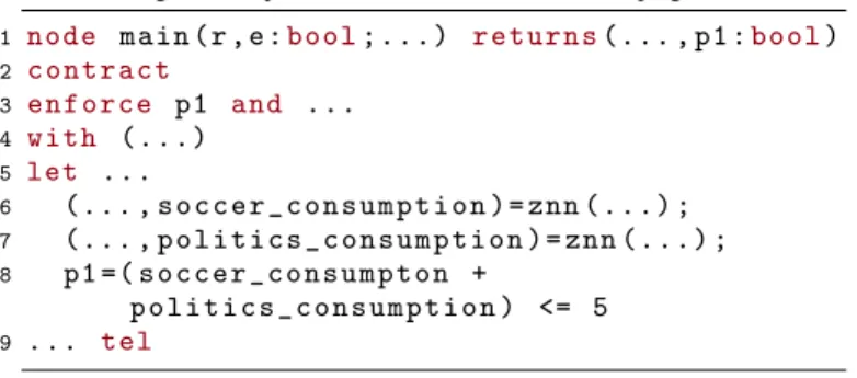
For illustration, Listing 9 shows how the last policy of the Main component (Listing 6, line 4) is translated into Hep-tagon/BZR. This constraint is defined as an equation (line 8) that depends on the integer outputssoccer consumptionand
politics consumption, which are produced by the respective instances of nodeznn(lines 6 and 7). This equation is hence used in the enforce block of the contract (line 3). Although the declaration of optimization objectives are currently not sup-ported by Heptagon/BZR, one may model a one-step optimiza-tion directly within the DCS tools Heptagon/BZR relies on [11] [22]. Please see [23] for more details.
Listing 9: Example of Constraint on Attribute in Heptagon/BZR. 1 n o d e m a i n ( r , e :b o o l; . . . ) r e t u r n s(... , p1 :b o o l) 2 c o n t r a c t 3 e n f o r c e p1 and ... 4 w i t h ( . . . ) 5 let ... 6 (... , s o c c e r _ c o n s u m p t i o n ) = znn ( . . . ) ; 7 (... , p o l i t i c s _ c o n s u m p t i o n ) = znn ( . . . ) ; 8 p1 =( s o c c e r _ c o n s u m p t o n + p o l i t i c s _ c o n s u m p t i o n ) <= 5 9 ... tel 4.4.2. Temporal Constraints
Temporal constraints refer to constraints on the logical or-der of configurations. They are modeled in Heptagon/BZR by a set of boolean equations of request (r) and end (e) sig-nals that are emitted by automata modeling behaviours. For simple constraints likeconf1 succeeds conf2(resp. conf1
precedes conf2), just a predicate like e con f 2 ⇒ r con f 1 (resp. e con f 1 ⇒ r con f 2) suffices. However, whenever there is a need for keeping track of the sequence of signals (to request and/or end configurations), the use of observer au-tomata is needed. Observer auau-tomata are placed in parallel with the behavior automata, and generated in Heptagon/BZR as part of the contract. The principle is to have an automaton that ob-serves the sequence of signals that leads to a policy violation and state that the state resulting from that sequence (an “error” state) should never be reached. Again, here we can rely on the enforce block of a Heptagon/BZR contract. The DCS objec-tive is the invariance of the state set deprived of those where the variable error is true.
Figure 14(a) depicts an observer that models the policy dur-ing (conf1 during conf2), where r1and r2(resp. e1and e2)
correspond to the request (resp. end) signal for configurations
conf1 and conf2, respectively. The error state (E) is reached if
conf2terminates beforeconf1(e2∧ ¬e1) or ifconf2terminates
before conf1 has started. The observer that models the con-straint between (conf1 between (conf2,conf3)) is depicted in Figure 14(b). Similarly, r1, r2 and r3 (resp. e1, e2 and e3)
correspond to the request (resp. end) signal for configurations
conf1,conf2andconf3, respectively. The automaton goes to the error state (E) whenever configurationconf3is started (r3
is emitted) after configurationconf2(e2), except when
configu-rationconf1is started and terminated (r1and e1) in the between.
E e1 r2∧ r1 r2∧ ¬r1 r1∧ ¬e2 e2∧ ¬e1 e2 (a) During E e2 e1∧ ¬r3∧ r2 e1∧ ¬r3∧ ¬r2 r2∧ ¬r3 r3∧ ¬e2 r3 e1 ∧ r3 (b) Between
Figure 14: Observer Automata for Temporal Constraints.
5. Implementation
5.1. FraSCAti and Service Component Architecture
Despite the fact that our contribution is technology-agnostic, for the sake of proof-of-concept, we rely on the Service Com-ponent Architecture (SCA)1as target component model. SCA
is a component model for building applications based on the Service Oriented Architecture principles. SCA provides means for constructing, assembling and deploying software compo-nents regardless of the programming language or protocol used to implement and make them communicate. Figure 15 depicts the basic concepts of SCA model illustrated with the Znn.com example. A component can be defined as simple or compos-ite, that is, composed of other components. A simple compo-nent is defined by an implementation, a set of services, refer-ences and properties. The implementation points to the actual implementation of the component (e.g., a Java Class). A ser-vice (resp. reference) refers to a business function provided (resp. required) by the component and is specified by an inter-face (e.g., via a Java Interinter-face). Properties are attributes defined within components whose values can be set/got from outside the component. In order for services, references and proper-ties be accessible from/or access outside the composite, they should be promoted to composite (or external) services /refer-ences/properties. Bindings define which methods and/or trans-ports (e.g., HTTP, SOAP 2) are allowed to access services or
to be accessed by references. Lastly, service and reference are connected by wires. main znn-soccer ... znn-politics External Service External Reference Promoted Reference Promoted
Service Property Access Wire Property
Composite lb:LoadBalancer as2:AppServer as1:AppServer as3:AppServer Binding Reference Service
Figure 15: Service Component Architecture Concepts in Znn.com.
The objective is that a middleware platform implementing the SCA specifications takes care of component implementa-tion, interoperability and communication details, so architects and developers can focus only on the architecture. In this work, we rely on the Java-based SCA middleware FraSCAti [4], since
1http://www.oasis-opencsa.org/
it provides mechanisms for runtime reconfiguration of SCA ap-plication. The FraSCAti Runtime is itself conceived relying on the SCA model, that is, it consists of a set of SCA components that can be deployed a la carte, according to the user’s needs. For instance, one can instantiate the frascati-fscript component, which provides services allowing for the execution of an SCA-variant of FPath/FScript [5], a domain-specific language for introspection and dynamic reconfiguration of Fractal compo-nents.
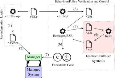
5.2. Compilation Tool-chain
As can be seen in Figure 16, the compilation process can be split into two parts: (i) the reconfiguration logics and (ii) the behaviour/policy control and verification. The reconfiguration logics is implemented by the ctrlf2fscript compiler, which takes as input a Ctrl-F definition and generates as output a FraSCAti FPath/FScript (1) containing a set procedures allowing going from one configuration to another. To that end, we rely on ex-isting differencing/match algorithms for object-oriented mod-els [24].
The script is later on used by a FraSCAti component (Man-ager) in charge of controlling the actual running component software system (2). Listing 10 shows an example of script describing a reconfiguration from configuration conf1 to conf2 of Znn component. In this example, the script just wires the reference of instance lb:LoadBalancer to the as2:AppServer in-stance’s service, then it starts the instance as2:AppServer.
Listing 10: Reconfiguration Logics in FScript. 1 a c t i o n c o n f 1 _ c o n f 2 ( znn ) { 2 s t o p( $ z n n / s c a c h i l d :: lb ) ; 3 r = $ z n n / s c a c h i l d :: l o a d b a l a n c e r / s c a r e f e r e n c e :: as2 ; 4 s = $ z n n / s c a c h i l d :: as2 / s c a r e f e r e n c e :: s ; 5 a d d s c a w i r e( $r , $s ) ; 6 s t a r t( $ z n n / s c a c h i l d :: as2 ) ; 7 s t a r t( $ z n n / s c a c h i l d :: lb ) ; 8 }
The behaviour control and verification is performed by the ctrlf2ept compiler, which takes as input a Ctrl-F definition and provides as output a synchronous reactive program in Heptagon/BZR (3). This code is given as input to the Hep-tagon/BZR compiler, which produces a code for the model checking and discrete controller synthesis tool (4). Hep-tagon/BZR is currently integrated with ReaX [22] tool. Thus, if the Heptagon/BZR code translated from the Ctrl-F description contains a contract with controllable variables, the tool gener-ates a controller (if there is any) such that the stated properties are guaranteed (5). Conversely, if there is no need for controller synthesis, the corresponding tool simply verifies the correctness of the Heptagon/BZR program. The Heptagon/BZR program corresponding to the target system model (3) along with the generated controller (5), if that is the case, are compiled again with the Heptagon/BZR compiler.
The result of the compilation of an Heptagon/BZR code is a sequential code (6) in a general-purpose programming language (in our case Java) comprising two methods: reset and step.
Discrete Controller Synthesis Ctrl-F ctrlf2ept *.ept Heptagon/BZR *.z3z Reax *.ept C Executable Code
Behaviour/Policy Verification and Control
ctrlf2fscript *.fscript Reconfiguration Logics Manager Managed System (4) (3) (5) (7) (6) (1) (2)
Figure 16: Ctrl-F Compilation Chain.
The former initializes the internal state of the program, whereas the latter is executed at each logical step to compute the output values based on a given vector of input values and the current state.
These methods are encapsulated by the FraSCAti component that controls the managed system (7) and they are typically used by first executing reset and then by enclosing step in an in-finite loop, in which each iteration corresponds to a reaction to an event (e.g., oload or uload), as sketched in Listing 11. The step method returns a set of signals corresponding to the start or stop of configurations (line 4). From these signals, we can find the appropriate script that embodies the reconfiguration actions to be executed (lines 5 and 6).
Listing 11: Control Loop Sketch. 1 r e s e t () ; 2 ... 3 on e v e n t o l o a d or u l o a d 4 <... , s t o p _ c o n f 1 , s t a r t _ c o n f 2 ,... >= s t e p ( oload , u l o a d ) ; 5 r e c o n f i g _ s c r i p t = f i n d _ s c r i p t (... , s t o p _ c o n f 1 , s t a r t _ c o n f 2 , . . . ) ; 6 e x e c u t e ( r e c o n f i g _ s c r i p t ) ;
5.3. Wrapping the Compilation Result into SCA Components We wrap the control loop logics into three components, which are enclosed by a composite named Manager. Com-ponent EventHandler exposes a service allowing itself to be sent events (e.g., oload and uload). The method implementing this service is defined as non-blocking so the incoming events are stored in a First-In-First-Out queue. Upon the arrival of an event coming from the Managed System (e.g., Znn.com), com-ponent EventHandler invokes the step method, implemented by component Architecture Analyzer. The step method output is sent to component Reconfigurator, that encompasses a method to find the proper reconfiguration script to be executed.
Manager FraSCAti Composite Event Handler Architecure Analyzer -reset(); -step(); Reconfigurator (*.fscript) Managed System frascati-fscript FraSCAti Runtime emit event load/execute *.fscript event non-blocking introspection/ reconfiguration
Figure 17: Manager Prototype Wrapping the Control Loop.
6. Case Studies
This section shows the application of Ctrl-F in two different situations. We first present an adaptive scenario by simulating the Znn.com case study, whose Ctrl-F model has been already detailed throughout the previous section. Then when provide a second case study, in which we apply Ctrl-F in order to control an application with a workflow of mutually exclusive tasks. 6.1. Case Study 1: Znn.com
Workload
Politics Soccer Constraint
0 1 2 3 4 5 Resource 0 0.5 0.7 Fidelity Idle Text LD HD as1 Idle Text LD HD as2 Idle Text LD HD as3 Idle Text LD HD as1 Idle Text LD HD as2 Idle Text LD HD 0 1 2 3 4 5 6 7 8 9 10 11 12 13 14 15 16 as3 Step
Figure 18: Execution of the Znn.com Adaptation Scenario.
We simulate the execution of the two instances of Znn.com application, namely soccer and politics, under the administra-tion of the Manager presented in previous secadministra-tion, to observe
the control of reconfigurations taking into account a sequence of input events. The behaviours of components AppServer and Znnare stated in Listings 4 and 5, respectively, while policies are defined in Listing 6 and 7.
As it can be observed in the first chart of Figure 18, we sched-uled a set of overload (oload) and underload (uload) events (vertical dashed lines), which simulate an increase followed by a decrease of the income workload for both soccer and politics instances. The other charts correspond to the overall resource consumption, the overall fidelity, and the fidelity level (i.e., con-figurations text, img-ld or img-hd) of the three instances of com-ponent AppServer contained in both instances of comcom-ponent Znn.
As the workload of politics increases, an event of type oload occurs at step 2. That triggers the reconfiguration of that instance from conf1 to conf2, that is, one more instance of AppServer is added within the Znninstance politics. We can observe also the progression in terms of resource consumption, as a consequence of this configuration. The same happens with soccerat step 3, and is repeated with politics and soccer again at steps 4 and 5. The difference, in this case, is that at step 4, the politics instance must reconfigure (to conf3) so as to cope with the current workload while keeping the overall consump-tion under control. In other words, it forces the AppServer in-stances as2 and as3 to degrade their fidelity level from img-hd to img-ld. It should be highlighted that although at least one of the AppServer instances (as2 or as3) could be at that time at maximum fidelity level, the knowledge on the possible future configurations guarantees the maximum overall fidelity for in-stance soccer to the detriment of a degraded fidelity for inin-stance politics, while respecting the temporal constraints expressed in Listing 7. Hence, at step 5, when the last oload event arrives, the fidelity level of soccer instance is preserved by gradually decreasing that of politics, that is, both instances as2 and as3 belonging to the politics instance are put in configuration text, but without jumping directly from from img-hd. At step 9, the first uload occurs as a consequence of the workload decrease. It triggers a reconfiguration in the politics instance as it goes from conf3 to conf2, that is, it releases one instance of AppServer (as3). The same happens with soccer at step 10, which makes room on the resources and therefore allows politics to bring back the fidelity level of its as2 to img-ld, and to the maxi-mum level again at step 11. This is repeated at steps 13 and 14 for instances politics and soccer respectively, bringing their consumptionsat the same levels as in the beginning.
6.2. Case Study 2: Mutual Exclusive Tasks
Figure 19 presents the example of a workflow, where boxes represent computing tasks to be executed, and where links are their execution dependencies from left to right. The application has parallel branches (indicated by a black dot), where all are executed starting at the same time. Alternative branches (indi-cated by a white dot) are also present: one and only of them will be executed, to be chosen by a controller according to the environing states and to a given global control objective coordi-nating parallel activities around constraints. These alternatives