HAL Id: hal-01823618
https://hal.archives-ouvertes.fr/hal-01823618
Submitted on 26 Jun 2018
HAL is a multi-disciplinary open access
archive for the deposit and dissemination of sci-entific research documents, whether they are pub-lished or not. The documents may come from teaching and research institutions in France or abroad, or from public or private research centers.
L’archive ouverte pluridisciplinaire HAL, est destinée au dépôt et à la diffusion de documents scientifiques de niveau recherche, publiés ou non, émanant des établissements d’enseignement et de recherche français ou étrangers, des laboratoires publics ou privés.
Adaptive control-theoretic detection of integrity attacks
against cyber-physical industrial systems
Jose Rubio-Hernan, Luca de Cicco, Joaquin Garcia-Alfaro
To cite this version:
Jose Rubio-Hernan, Luca de Cicco, Joaquin Garcia-Alfaro. Adaptive control-theoretic detection of integrity attacks against cyber-physical industrial systems. Transactions on emerging telecommuni-cations technologies, Wiley-Blackwell, 2018, 29 (7), pp.e3209-1 - e3209-17. �10.1002/ett.3209�. �hal-01823618�
Adaptive control-theoretic detection of integrity attacks against
cyber-physical industrial systems
Jose Rubio-Hernan
1Luca De Cicco
2Joaquin Garcia-Alfaro
11SAMOVAR, Telecom SudParis, CNRS, Université Paris-Saclay, Evry, France 2Politecnico di Bari, Dipartimento di Ingegneria Elettrica e dell'Informazione, Bari, Italy
Correspondence
Joaquin Garcia-Alfaro, SAMOVAR, Telecom SudParis, CNRS, Université Paris-Saclay, Evry, France. Email: joaquin.garcia_alfaro@ telecom-sudparis.com Funding information Cyber CNI Chair of the Institut
Mines-Télécom; Airbus Defence and Space, Amossys, EDF, Orange, La Poste, Nokia, Société Générale and the Regional Council of Brittany
Abstract
The use of control-theoretic solutions to detect attacks against cyber-physical indus-trial systems is a growing area of research. Traditional literature proposes the use of control strategies to retain, eg, satisfactory close-loop performance, as well as safety properties, when a communication network connects the distributed components of a physical system (eg, sensors, actuators, and controllers). However, the adaptation of these strategies to handle security incidents is an ongoing challenge. In this paper, we survey the advantages of a watermark-based detector against some integrity attacks as well as the weaknesses against other attacks. To cover these weaknesses, we pro-pose a new control and security strategy that complements the watermark-based detector. We validate the detection efficiency of the new strategy via numeric sim-ulation. Experimental results are also presented by using a laboratory testbed based on supervisory control and data acquisition industrial protocols.
1
I N T R O D U C T I O N
In an effort to reducing complexity and costs, industrial infrastructures are being upgraded with novel computing, communica-tion, and interconnection capabilities. The goal is to build and operate them as easily and reliably as possible. Current trends, such as smart factories and intelligent supply chains mainly rely on sensors, actuators, and controllers that are networked to communicate with each other by using cyber-physical industrial protocols.1,2However, this opens challenging security threats.3
The recently coined cyber-physical security term refers to mechanisms that address security issues associated to these environ-ments. The use of inadequate cyber-physical security mechanisms can have an adverse effect in smart industries.4-6These issues
place the study of cyber-physical security mechanisms as a hot research topic.
Given the control-theoretic nature of cyber-physical industrial systems, the control community is actively working to adapt tra-ditional control strategies to detect faults and errors, toward detectors of malicious attacks.7-9Motivated by the same objectives,
we present in this paper a solution that combines 2 different control strategies to handle integrity attacks against cyber-physical systems. The new solution combines an event-triggered control strategy together with a challenge-response watermark-based detector. We present the theoretical approach underlying our proposed strategy as well as its algorithmic implementation. We validate our proposed approach via numerical simulations, complemented by experimental results obtained using a laboratory testbed based on supervisory control and data acquisition (SCADA) industrial protocols.
This paper is organized as follows. Section 3 provides introductory background. Section 4 presents our detection strat-egy. Section 5 validates the approach via numerical simulations. Section 6 complements the simulations with experimental results obtained with a laboratory testbed based on SCADA protocols. Section 2 surveys related work. Section 7 concludes this paper.
2 of 17
R E L A T E D W O R K
Security of cyber-physical systems is drawing a great deal of attention recently.10Solutions focused on control approaches for
the detection of cyber-physical attacks are the research axis more closely related to this paper. This axis is the one that explicitly considers the interconnection between cyber and physical control domains in networked control systems. Recently, the control system community started to study the security of cyber-physical systems both under the methodological point of view and from a more technological standpoint by looking at particular problems arising in, eg, smart grids. Concerning the methodological aspects, several studies have proposed to adapt classical frameworks to handle security issues in networked control systems.
In a cyber-physical replay attack, the adversary aims at carrying out malicious actions without holding a priori knowledge about system model dynamics. Most of the other cyber-physical attacks reported in the literature require that the adversary gathers some system knowledge. For example, to execute a dynamic false-data injection attack,11the adversary has to have a
perfect knowledge of the plant's behavior. Likewise, to execute a covert attack,12it is necessary to have some knowledge about
the model of the plant and the controller. The adversaries handled in this paper fit those aforementioned models defined in the works of Garone et al,11 and Smith,12ie, it is assumed that they aim at obtaining knowledge about the model underlying the
behavior of the plant and the controllers prior attacking the system.
Concerning detection mechanisms, previous work in the related literature considers the adaptation of fault detection systems to detect cyber-physical attacks.13-15In particular, Mo et al13and Mo and Sinopoli16proposed the use of the watermark-based
detection by adapting traditional failure detection mechanisms to detect replay attacks. This watermark is added to the control measurements to verify using the detection mechanism that the sensor measurements are not replayed measurements, ie, the control measurements with the watermark have to be correlated with the sensor measurements. Miao et al17 improved the
performance of this detection mechanism. They present a suboptimal algorithm against replay attack, using a stochastic game approach. This suboptimal algorithm combines the watermark-based detector proposed by Mo et al and the zero-sum stochastic game proposed by Zhu and Ba¸sar.18In the same way, Do et al19formulated the attack detection problem as a transient changes
detection problem in stochastic-dynamical systems. This detector is based on the knowledge of the behavior of the system and its stochastic variations to detect data manipulation. Using this detection control algorithm allows to protect the system against attacks able to perform malicious actions in a short period of time, of which goal is to disrupt safety-critical applications. An alternative approach is taken by Pasqualetti et al,15where the authors propose to use the theory of geometric control to model
cyber-physical systems attacks. In line with the aforementioned approach, this paper focuses on the interconnection between control strategies and a watermark detector to handle the integrity attacks.
3
B A C K G R O U N D
3.1
Cyber-physical attacks
Some of the abbreviations used hereinafter are summarized in Table 1. The coined cyber-physical industrial system term inte-grates a physical infrastructure and a cyber framework in an effort to automate physical processes, as well as reducing complexity and costs of traditional industrial systems. These traditional systems are composed of sensors, actuators, and other devices that
TABLE 1 Abbreviations used in this paper
Acronyms Descriptions
CPS Cyber-physical system
SCADA Supervisory control and data acquisition
NCS Networked control system
IT Information technology
ETC Event-triggered control
PETC Periodical event-triggered control
LTI Linear time invariant
LQG Linear quadratic Gaussian
PIETC-WD Periodical and intermittent event-triggered control and watermark detector
PLC Programmable logic controller
RTU Remote terminal units
ARX Autoregressive with exogenous input
interact with the physical processes. The technology evolution brings these systems toward a combination between a physical layer, which encompasses the physical framework, and a cyber layer that encompasses the communication and computation framework,20eg, by using SCADA technologies.
Cyber-physical systems combine control strategies through the communication network that are used to manage the physical layer with some cyber strategies and used to monitor the physical layer. The cyber layer has to follow some constraints driven by control strategies that also appear as constraints at the physical layer. Attacks targeting both layers are often referred to as cyber-physical attacks. In a nutshell, cyber-physical attacks aim at affecting physical processes of a networked control system by manipulating network information at the cyber layer.
Teixeira et al14proposed a taxonomy of cyber-physical attacks based on the resources of the adversaries. For instance, the
knowledge of the adversary about the system is an important resource to assess the nature of the attacks. Based on the degree of the adversary knowledge, the attacks may succeed at violating some system properties, such as availability and integrity, as well as to obtaining operational information about the system itself to cover the attacks from detection. Mo et al13 addressed
the traditional replay attacks, in which the adversary does not hold any a priori knowledge about the system dynamics. They also address injection attacks, as a variant of the previous type, in which the adversary injects false data or alterations from legitimate data.
Those aforementioned attacks are also addressed by Teixeira et al14but classified in a more granular manner (depending on
the techniques to inject the malicious data) as surge attacks, bias injection attacks, and geometric attacks. In order to perform such attacks, the adversary must hold some partial knowledge about the physical processes underlying the target system. Smith12
presented a more powerful attack type, referred to as covert attacks, in which the adversary must perfectly know the system dynamics, to evade detection. To acquire the system knowledge, adversaries are assumed to learn and identify as much informa-tion as possible from the network or physical data. Rubio-Hernan et al21,22differentiated between parametric and nonparametric
adversaries, depending on the identification techniques used to obtain such system knowledge.
In terms of attack detection, several techniques have been proposed in the literature. Wang et al23proposed the use of relation
graphs to identify false data from injection attacks. Arvani and Rao24 proposed a signal-based intrusion detection model to
identify anomalies in the information reported by the sensors of cyber-physical systems. Do et al19presented the use of statistical
detection methods, to identify data manipulation over stochastic processes. The use of watermark-based techniques are proposed by Mo et al13and revisited by Rubio-Hernan et al.21,22 Next, we reexamine the watermark-based techniques presented in the
works of Mo et al13and Rubio-Hernan et al21,22and show how to combine such techniques together with control strategy policies.
We show that the resulting combination succeeds at handling the most powerful types of cyber-physical adversaries reported in the literature, ie, cyber-physical adversaries holding complete knowledge about the system dynamics.
3.2
Control strategies
Control theory is a well-known topic, where the evolution of the technology has been the main motivation to create new control policies to manage these systems, keeping the control features. Among these new technologies, we can mention the networked control systems, where the loop between the different components of the system is closed through the network. The evolution of networked control systems to deal with the industry 4.0 is defined as cyber-physical industrial system. These new defined systems need the collaboration among a very wide number of disciplines to solve the challenges in term of autonomy, reliability, usability, functionality, and cyber security.25
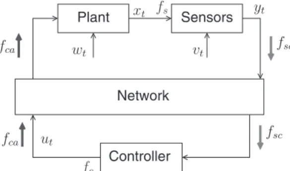
Figure 1 shows a simple cyber-physical industrial system diagram, where fsand fcare the frequencies used by the sensors and
controller, respectively, to process data. fcais the sampling frequency used in the communication channels between the controller
and the actuators. fscis the sampling frequency used in the communication channels between the sensors and the controller.
Among control strategies used in cyber-physical industrial systems, we focus on strategies depending on the transmission policy necessary to secure the system. We assume policies not only to identify control faults but also intentional attacks carried out by external entities. Such policies can be classified as either sampled-data control policies or event-triggered control policies. In the case of sampled-data control policies, the system can be driven using either monofrequency sampling (ie, same sampling frequency for all the channels) or multifrequency sampling (ie, different sampling frequencies depending on the channel, such as sensor-to-controller channel, or controller-to-actuator channel7). Figure 1, case 1, represents a monofrequency sampling
scenario. Figure 1, case 2, represents a multifrequency sampling scenario.
Security in cyber-physical systems shall include the management of control properties and policies through the network, to avoid that an external entity, eg, an adversary, succeeds at harming the system. In the case of event-triggered control policies, we can differentiate between continuous event-triggered control26policies, where all the data received by the sensors are sent to the
4 of 17
Network
Plant Sensors
Controller
FIGURE 1 Cyber-physical system diagram. Case 1: fca= fsc. Case 2: fca≠ fsc. Case 3: fca= fc, fsc= fs, and fs= fc. Case 4: fca= fc
pa, fsc=
fs
ps,
such that pa, ps∈N. Case 5: fscand fca→stochastic events
controller; periodic event-triggered control8policies, where sensors send update data periodically; and stochastic event-triggered
schedule9policies, where sensors send update data only when there are variations in data obtained. Figure 1, cases 3, 4, and 5,
represent each of these different types of policies.
3.3
Watermark-based attack detection
We address in this section the watermark-based detector proposed by Mo et al.13 The goal of such a detector is to identify
cyber-physical replay attacks against networked control industrial systems. To analyze the watermark-based detector, Mo et al used an industrial control system modeled mathematically as a discrete linear time-invariant system. This mathematical model is used to describe the dynamic behavior of the system. The system can be represented as follows:
xt+1= Axt+ But+ wt (1)
yt= Cxt+ vt, (2)
where xt ∈ Rnis the state's vector, ut ∈ Rp is the control signal, yt ∈ Rmis the system output, and wt ∈ Rnand vtare the
process noise and the measurement noise, respectively. The noises are assumed to be a zero mean Gaussian white noise with
covariance Q, ie, wt ∼ N(0, Q) and R, ie, vt ∼ N(0, R), respectively. Moreover, A ∈ Rn×n, B ∈ Rn×p, and C ∈ Rm×nare the
state matrix, the input matrix, and the output matrix, respectively. Let us now define the well-known linear quadratic Gaussian
(LQG) approach used as a control technique in the work of Mo et al.13This technique has 2 independent components.
1. a Kalman filter producing an optimal state estimation̂xtof the state x:
̂xt|t−1= Âxt−1+ But−1
̂xt=̂xt|t−1+ Kt( yt− Ĉxt|t−1), (3)
where Ktdenotes the Kalman gain, and̂xt|t−1is the a priori system state estimation.
2. a linear quadratic regulator providing the control law ut.
ut= L̂xt, (4)
where L denotes the feedback gain of a linear-quadratic regulator.
After describing the model of the plant, hereinafter, we present the detection scheme proposed in the work of Mo et al13
against replay attacks.
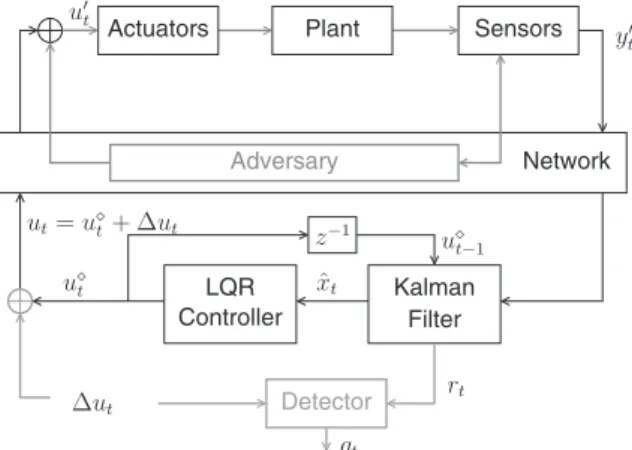
The idea is to superpose a watermark signal Δut∈Rpto the optimal control law u⋄t. The new control input utis given by
ut= u⋄t + Δut. (5)
Note that the watermark signal is independent from the process noise wtand the output noise vt. To detect the adversaries,
the watermark-based detector employs a well-known χ2detector.27Figure 2 shows the overall control system equipped with the
attack detector proposed in the work of Mo et al.13The alarm signal g
tgenerated by the detector is defined as follows:
gt= t
∑
i=t−w+1
(ri)T−1(ri), (6)
where w is the size of the detection window, is the covariance of input signals from the sensors, and rt= yt− Ĉxt|t−1is the
LQR Controller Plant Sensors Kalman Filter Actuators Network Adversary Detector
FIGURE 2 Watermark protection in cyber-physical systems.13LQR, linear quadratic regulator
To verify if the system is under attack, gtis compared with threshold γ. If gtis equal or greater than the threshold, gt ≥ γ,
then the detector generates an alarm. The aforementioned threshold is chosen with respect to the system properties, eg, during the system identification phase, to keep a proper ratio of false positives and detector efficiency.
3.4
Watermark-based attack detection against cyber-physical adversaries
The stationary challenge-response watermark-based detector proposed in the work of Mo et al13has been analyzed and revisited
in the work of Rubio-Hernan et al.21,22In the work of Rubio-Hernan,21a new adversary, named nonparametric cyber-physical
adversary is defined to show some weaknesses of using a stationary watermark in the detector. The adversary is able to use nonparametric identification techniques to identify the behavior of the system from the input and output data of the system, ie, from data sent to the actuator and data received from the sensors. This adversary bases the attack on the stationarity of the data. These stationary data allows the adversary to identify the correlation between the different events executed in the system. To handle such a vulnerability, a new watermark-based detector is proposed in the work of Rubio-Hernan et al.21The new approach
uses different distributions to move toward an adaptive, and nonstationary, watermark-based detector with 2 main configurable parameters: the number of distributions N and the switching frequency f = 1∕T. The new watermark is defined as follows:
Δut= Δu(s(tt ,T)), (7)
where s ∶N × R → , = {0, 1, … , N − 1}, is a static function that maps the time sample t and the switching period T to an element of the index set, defined as follows:
s(t, T) =⌊1
T mod (t, NT)
⌋
, (8)
where mod(x, y) is the modulo operator, and ⌊·⌋ is the floor function.
The new watermark-based detector has been analyzed in the work of Rubio-Hernan et al22against a more powerful adversary.
The new adversary, as in the case of the nonparametric adversary, uses parametric identification techniques to obtain a precise version of the system model. Unlike the nonparametric adversary, the techniques used by the new adversary aim at computing some precise system parameters. This allows to obtain the behavior of the system regardless of using nonstationary watermarks. To do so, the new adversary needs to guess 2 main configuration parameters: the precise number of samples to identify the system and the order of the system, ie, the dimension of the correlation matrix between the input and the output. This new adversary is able to evade detection if those 2 aforementioned parameters are properly chosen. In the following section, we present a new strategy to handle the adversary presented in the work of Rubio-Hernan et al.22
3.4.1
Performance loss
The quadratic cost J of a LQG controller, with respect to the state xtand the control input ut, can be obtained using the following
expression: J = lim n→∞E [ 1 n n−1 ∑ i=0 ( xTiΓxi+ uTiΩui )] , (9)
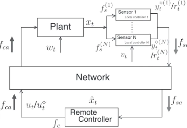
6 of 17 Network Plant Controller Remote Sensor 1 Sensor N Local controller 1 Local controller N
FIGURE 3 Cyber-physical system diagram with the new control security strategy
where Γ and Ω represent positive definite cost matrices.28 The strategy proposed in this paper uses 2 detectors previously
proposed in the works of Mo and Sinopoli16and Rubio-Hernan et al.21Both detectors use the theoretical methodology proposed
by Mo et al,13to compute optimal detection, in terms of performance loss. Our approach does not increase the performance loss
with respect to previous work.
4
P I E T C- W D W A T E R M A R K- B A S E D D E T E C T I O N S T R A T E G Y
In the previous section, we have seen that the watermark-based schemes are able to handle attacks carried out by adversaries with limited knowledge about the system dynamics, for instance, the ones defined as either cyber adversaries or nonparametric cyber-physical adversaries (cf Section 3.4). Nevertheless, it fails at detecting those adversaries with enough knowledge about the system dynamics, defined as parametric cyber-physical adversaries (cf Section 3.4). In this section, we present a new detector scheme, hereinafter denoted as periodic and intermittent event-triggered control watermark detector (PIETC-WD). This new detector aims at detecting cyber adversaries as replay attack and the cyber-physical adversaries presented in previous section.
Our scheme consists of a local controller located in each sensor and a remote controller creating a distributed controller (cf Figure 3). The cooperation between the local and the remote controller allows us to create an intrusion detection policy to capture integrity attacks. The local controllers manage the dynamics of the plant, and the remote controller manages the closed-loop system to ensure the system against integrity attacks. Notice that our new scheme requires an additional controller, together with the sensors, which must have enough computation power to process data estimations, eg, to predict errors between environmental and estimated data. The actuators do not require additional computational power. Nevertheless, during the time between 2 consecutive events, they must keep the last data received from the remote controller.
To perform with our scheme, it is necessary to define communication policies among the sensors, the actuators, and the remote controller. We define 2 communication policies for ensuring the system: (1) periodic communication policy, which the communication from the sensors to the remote controller is periodical, with a Tsc= 1∕fscperiod, and from the remote controller
to the actuators, with a Tca= 1∕fcaperiod; and (2) intermittent communication policy, which allows for sending data from the
sensors to the remote controller if the local controller produces an alarm. Notice that Tsccannot be equal to Tcato avoid that an
intermittent communication takes place while the periodic communication is being sent.
Definition 1. Periodic and intermittent event-triggered control watermark detector is a detector strategy with dis-tributed control tasks. On one hand, the sensors control the system periodically, using their local controllers and a local watermark-based detector.13 On the other hand, the remote controller uses the estimation error received from each
sen-sor to periodically generate the control inputs. The remote controller also controls the closed-loop communication with an intermittent watermark.
The PIETC-WD strategy uses essential properties from cyber-physical systems, to detect the attacks. The 3 main properties used in our work are as follows: (1) stability of closed-loop systems; (2) controllability of the system, to get full reachability; and (3) observability, to correlate events from the system. The periodic communication policy of PIETC-WD uses these 3 properties to verify if the system works properly, with regard to the information (eg, measurements) provided by the sensors. The intermittent communication policy verifies the stability of the closed loop from the controller standpoint, to avoid manipulation from external agents.
The communication algorithms, used to perform the PIETC-WD strategy, are shown in Algorithms 1 and 2. Algorithm 1 shows the local controller implementation, placed in the sensors, whose input is the data obtained from the physical system,
yi
t, and its output is the residue of the local controllers, r i
t(with a challenge response watermark), if the alarm is disabled; or
the value obtained by the sensors, yit, if the alarm is enabled. Algorithm 2 shows the remote controller implementation, whose
input is the data sent by the sensors, datasc; and its output is the control inputs sent by the controller, dataca, and the alarm
value, alarmc. More information about the controllers and the communication policies is provided in the sequel. The following
notation will be used hereinafter:
U = {u0, uTca, … , u𝜅Tca} control input variables
Y = {y0, yTsc, … , yηTsc} observed measurements,
where αTca= Tscwith α, η and𝜅 ∈N.
4.1
Local controller design
The local controller is located in the sensors and uses a watermark to verify that the dynamics of the system is correct. Each sensor has a local controller with an LQG approach (cf Section 3.3). We denote the local controller in each sensor by i ∈ {0, 1, … , N − 1}, where N is the number of sensors in the system. This controller adds a watermark to the sensor measurement before sending the residue to the remote controller
y(i)t = y⋄(i)t + Δy
(i)
t (10)
rt(i)= y(i)t − Cîx(i)t|t−1, (11)
where y⋄(i)t is the sensor measurement, Δy
(i)
t is the watermark added by the local controllers, and r
(i)
t is the residue sent to the
remote controller to compute the control input ut= [u(0), … , u(N−1)]. Notice that the new sensor measurement y(i)t is computed
after verifying that y⋄(i)t is the correct sensor measurement.
4.1.1
Remote controller design
The remote controller receives periodically the residue of each sensor, r(i)t , and computes these residues using the LQG approach
(cf Section 3.3) to obtain the state estimation
8 of 17 RUBIO-HERNANET AL.
and
rt= rτ
∀t ∈ [τ, τ + (α − 1)Tca],
(13) where rtis a vector generated by all the residues of the sensors and rτwith τ ∈ [t ∶ mod(t, Tsc) = 0] is the periodical residues'
vector. In Equation 12,̂xt|t−ϱis defined as
̂xt|t−ϱ= Aϱ̂xt|t−ϱ+ ϱ ∑ j=1 Aj−1Buϱ−j+1, (14) where ϱ ∈ {1, … , α}.
Equation 12 works properly if the data used by each sensor are independent among them or the system has only one sensor. Otherwise, if the data received by sensors are correlated, it is necessary to add a rectification for each sensor's residue to consider the cross-correlation among the watermarks added by local controllers. We can compute this rectification for t ∈ [T0, T0+ T − 1]
as follows:
where rrectt (i) is the rectified value respect to different sensors. In addition, Δ̂x i t|t−T is the rectification. Δ̂xit|t−T = t−T∑0−1 j=0 ( (Ai+ BiLi)j+1Ki(ϵr) ) , (16) where ϵr= rt−1−j− rt−1−j(i) .
We can define the control inputs vector, ut, as follows:
ut= L ( ̂xt|t−ϱ+ Ktrrectt ) = L(̂xt|t−ϱ+ Kt(r∗t + Δyt) ) , (17)
where rt∗ is the vector of the residues before adding the watermark and their respective rectification, and Δyt is the vector
generated by all the sensors' watermarks.
The watermark used intermittently by the remote controller is added to the control inputs. The controller adds a watermark with probability β. Denoting λt= 1 or 0 as indication function whether the watermark is added or not, we assume that λ
′ s are
independent and identically distributed (iid). Bernoulli random variables with E[λt] = β.
The intermittence of the watermark communication allows us to define the watermark behavior as a nonstationary distribution. This watermark, Δut(cf Equation 5), permits us to detect if the closed loop is being manipulated. It is worth noting that Δutis
a stochastic signal with the same variance as Δyt.
4.2
Periodic communication policy
The periodic communication policy is managed by the sensors. The sensors add the watermark in the measurements received by the plant and send residue rtto the remote controller. The remote controller uses these residues to generate the control inputs
sent to the actuators. The actions of these actuators produce change in the state of the plant that is captured by the sensors. If the real states differ from the state estimated by the sensors, then the sensors will switch from periodic communication policy to intermittent communication policy (cf Section 4.3).
In order to validate the proposal, let us assume that an attack is started at time T0, and we compute residue rt(i) for t ∈
[T0, T0+ T − 1]
r(i)t = y
′(i)
t − Cîx(i)t|t−T, (18)
where y′(i)t is the sensor measurement sent to the controller by the adversary. Moreover, it is easy to show that the following
holds: ̂x(i) t|t−T =̂x ′(i) t|t−T + t−T0 i ( ̂x(i) T0|T0−1−̂x ′(i) T0|T0−1 ) + t−T∑0−1 j=0 ( j (Ai+ BiLi)Ki(ϵΔy) )
where ϵΔy = (Δy(i)t−1−j− Δy′(i)t−1−j),̂x′(i)is the local estimated state for each sensor when the system is under attack, andi =
(Ai+ BiLi)(Ii− KiCi) is a stable matrix.13Substitution of 19 in 18 yields
rt(i)= y ′(i) t − Cîx′(i)t|t−T ⏟⏞⏞⏞⏞⏞⏟⏞⏞⏞⏞⏞⏟ First term − Cit−Ti 0 ( ̂x(i) T0|T0−1−̂x ′(i) T0|T0−1 ) ⏟⏞⏞⏞⏞⏞⏞⏞⏞⏞⏞⏞⏞⏞⏞⏞⏞⏞⏞⏞⏟⏞⏞⏞⏞⏞⏞⏞⏞⏞⏞⏞⏞⏞⏞⏞⏞⏞⏞⏞⏟ Second term − Ci t−T∑0−1 j=0 ( j (Ai+ BiLi)Ki(ϵΔy) ) ⏟⏞⏞⏞⏞⏞⏞⏞⏞⏞⏞⏞⏞⏞⏞⏞⏞⏞⏞⏞⏞⏞⏟⏞⏞⏞⏞⏞⏞⏞⏞⏞⏞⏞⏞⏞⏞⏞⏞⏞⏞⏞⏞⏞⏟ Third term .
Let us consider separately the 3 terms in the equation written above: the first term follows the same distribution of ( yt−Cîx(i)t|t−1);
sincei is asymptotically stable, ie, all its eigenvalues are inside the open unit disk of the complex plane, the second term
converges exponentially to zero. In fact, the entries oft−T0
i converge exponentially fast to zero. The third term, under attack,
is not equal to zero, since Δy(i)t ≠ Δy′(i)t , and the adversary is detected; for a cyber adversary viewpoint, the measurements of the sensors change all the time and replay measurements are not accepted; likewise, a cyber-physical adversary is not able to obtain the system model using the methodology proposed in Section 3.4. The parametric cyber-physical adversary model, Hat,
using the autoregressive with exogenous input identification approach,29is computed as follows:
Hat = fat(ut, rt, yt, vt), (19)
where fatis a linear function that map the input ut, as a function of t to the output (residue rt, or measurement yt) using a process
10 of 17 RUBIO-HERNANET AL.
Assuming that the real model is, H = f (ut, yt, vt), a linear function. Furthermore, the model shown by the system is H =
fs(rt, yt, vt, ut, Δut, Δyt), a non linear function, because we add an Δyt in the measurements of the sensors periodically and an
Δutin control input, as stochastic event, avoiding to follow a linear function to describe the system. For this reason, a powerful
cyber-physical adversary is detected.
4.3
Intermittent communication policy
The aforementioned periodic communication policy is managed by the sensors. The sensors produce an alarm if gt≥ γ. When
a sensor produces an alarm, this information is sent immediately to the remote controller. The affected sensor sends the real measurement to the remote controller to perform a second verification. This alarm is activated in a sensor if the control input has been manipulated by an external entity, a problem occurs in the system or the remote controller adds the watermark in the control input.
As we have defined before, a remote controller can generate an intermittent communication to verify that the closed loop is not broken. For a SISO (single-input, single-output) system or SIMO (single-input, single-output) system, the remote controller follows the next steps.
• The controller uses a low-pass filter after computing the control input, ut, to remove the variations, and generate an optimal
control input, u∗ t. u∗t = L ( ̂xt|t−ϱ+ Ktrt∗ ) (20)
• The remote controller adds the owns watermark.
ut= L
(
̂xt|t−ϱ+ Ktr∗t
)
+ Δut (21)
The local controllers located in the sensors receive the modification. They generate an alarm and send the measurement of the sensors to the remote controller. Then, the remote controller verifies if the measurement of the sensors is correct using the χ2detector. If the detector value is under the threshold, the system works correctly. Otherwise, if this value is over the threshold,
the remote controller generates an alarm. In both cases, the next control input is computed as follows:
ut+Tca = L
(
̂xt|t−ϱ+ Ktrt
)
, (22)
where residue rtfollows Equation 13.
For a MISO (multiple-input, single-output) system or a MIMO (multiple-input, multiple-output) system the remote controller follows the next steps:
• The controller computes the control input:
ut= L(̂xt|t−ϱ+ Ktrt)
=[u(1), … , u(i), … , u(n)], (23)
where n is the number of control inputs.
• Then the new control input vector is generated as follows:
ut { ut = [ u(1), … , u(i), … , u(n)] ∀i≠ j u(i)t = u ∗(i) t + Δu (i) t i = j ,
where u∗( j)t is the control input of the actuator, j, filtered to remove the variations. After removing the variation, the remote
controller adds its watermark. It is worth noting that j is the actuator chosen by the controller to send the watermark. As we have shown before, if the detector value, generated from the real data sent by the sensor, is under the threshold, the next control input is computed as follows:
ut+Tca = L(̂xt|t−ϱ+ Ktrt). (24)
Otherwise, the remote controller generates an alarm.
Briefly, when the remote controller receives a measurement from a sensor, if a watermark Δu has not been sent, then the remote controller creates an intrusion alarm. Otherwise, if a watermark has been added to the control input, the controller verifies if this alarm is produced by the watermark. If the residue generated between the real measurements of the sensors and
the estimation is under the threshold, the remote controller sends the control input generated before adding the watermark. However, if the residue is over the threshold, it means that an external entity is into the closed loop, and an alarm is activated.
In order to validate our claims, let us assume the following attack in the communication channel between the sensor and the controller after the controller sends a control input with a watermark. It is started at time T0, and the remote controller includes
the remote watermark, Δutat time T1∈ [T0, T0+ T − 1]. We compute the residues rtfor t ∈ [T0, T0+ T − 1]:
rt { rt= [ r(1), … , r(i), … , r(n)] t ∈ [T0, T1] rt= y′t− Ĉxt|t−T t ∈ [T1, T0+ T − 1] . (25)
On one hand, it is worth noting that the attack is not detected between T0and T1, since the adversary is able to replay or insert
a correct residue without being detected. On the other hand, for t ∈ [T1, T0+ T − 1], it is easy to show that the following holds:
̂xt|t−T =̂x′t|t−T+t−T1 ( ̂xT1|T1−1−̂x ′ T1|T1−1 ) + t−T∑1−1 j=0 ( j B(Δut−1−j− Δu′t−1−j )) . (26) Substitution of (26) in (25) yields: rt= y′t− Ĉx′t|t−T ⏟⏞⏞⏞⏟⏞⏞⏞⏟ First term − Ct−T1 ( ̂xT1|T1−1−̂x ′ T1|T1−1 ) ⏟⏞⏞⏞⏞⏞⏞⏞⏞⏞⏞⏞⏞⏞⏞⏞⏞⏞⏞⏟⏞⏞⏞⏞⏞⏞⏞⏞⏞⏞⏞⏞⏞⏞⏞⏞⏞⏞⏟ Second term − C t−T∑1−1 j=0 ( j B(Δut−1−j− Δu′t−1−j )) ⏟⏞⏞⏞⏞⏞⏞⏞⏞⏞⏞⏞⏞⏞⏞⏞⏞⏞⏞⏞⏞⏞⏞⏞⏞⏞⏞⏟⏞⏞⏞⏞⏞⏞⏞⏞⏞⏞⏞⏞⏞⏞⏞⏞⏞⏞⏞⏞⏞⏞⏞⏞⏞⏞⏟ Third term .
The first term follows the same distribution of ( yt− Ĉxt|t−1); the second term converges exponentially to zero. Since the third
term is not equal to zero, Δut ≠ Δu′t, the adversary is detected; from the cyber adversary viewpoint, the measurements of the
sensors change all the time and replay measurements are not accepted; likewise, the cyber-physical adversary is not able to obtain the system model.
4.4
New parametric cyber-physical adversary
In this section, we present a new parametric cyber-physical adversary with the knowledge about the new detector strategy, to evaluate new detection strategy. This attacker has knowledge about the new communication policies and the existence of the local and the remote watermarks. Nevertheless, the new adversary does not know the watermark covariances, the controller's param-eters used to obtain the correct error between data, and neither the moment when the remote controller forces an intermittent communication.
The new adversary could be able to detect the correlation model between the inputs and the outputs of the plant. This adversary can force the sensors' intermittent communication with malfunction control inputs, and mislead the controller with replay error data to obtain the model. Nevertheless, this adversary is not able to know when the communication is periodic or intermittent, since the attacker does not know when the remote control sends the watermark added to the control inputs, which generate the intermittent communication. The intermittent communication does not change the communication between the remote controller and the actuators, but produces an intermittent communication between the sensors and the remote controller, necessary to verify the closed loop.
Briefly, the new adversary is able to attack the integrity of the system. Nevertheless using the PIETC-WD strategy, the adversary is detected by the controllers of the sensors. The remote controller detects the attack when it verifies the behavior of the closed loop. The adversary cannot avoid the alarm in the sensors (local controller). Nevertheless, the attacker can cut off the communication between the sensors and the remote control misleading the remote controller with correct residues (eg, replay residues). Moreover, to avoid the alarm in the remote controller, the adversary can switch between sending the measurements of the sensors or the residues, but the adversary has a great probability to be detected. We validate the PIETC-WD strategy against the new parametric cyber-physical adversary in the next section.
5
N U M E R I C A L V A L I D A T I O N
This section presents a numerical validation of the strategy. We have simulated a multiple-input–multiple-output system, which represents a cyber-physical system with 4 inputs and 4 outputs. To define mathematically this system using the model shown
12 of 17
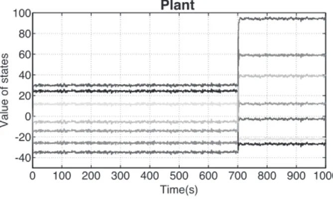
FIGURE 4 The dynamics of the states vector in the plant under a parametric attack. The attack starts at t = 700s
in Section 3.3, we use the following matrices*:
A = ⎡ ⎢ ⎢ ⎢ ⎢ ⎢ ⎢ ⎣ −0.199 0.145 −0.01 −0.119 0.062 0.134 0.001 0.0413 −0.189 −0.124 0.037 0.167 0.059 0 0.031 −0.097 −0.344 −0.055 −0.138 0.213 −0.002 −0.156 −0.030 0.042 −0.014 0.005 0.143 0 −0.016 0.162 −0.129 0.118 −0.199 0.005 0.001 0.096 0.082 0.203 0.042 −0.028 −0.147 0 −0.250 0.087 −0.064 −0.134 −0.093 0.075 0.447 ⎤ ⎥ ⎥ ⎥ ⎥ ⎥ ⎥ ⎦ , B = ⎡ ⎢ ⎢ ⎢ ⎢ ⎢ ⎢ ⎣ −1.739 0 0 0 −0.214 0 0.702 0 1.437 0.001 −1.6 −0.711 −1.107 0.002 0 1.548 0 0 −0.952 0 1.197 0 −1.01 0 0.953 0.765 −1.44 0 ⎤ ⎥ ⎥ ⎥ ⎥ ⎥ ⎥ ⎦ , C = ⎡ ⎢ ⎢ ⎢ ⎣ −2.261 1.112 −0.09 0 0.457 0.829 −1.137 0.091 0.259 0.876 −0.273 2.236 −1.484 −1.091 0 0.689 −0.074 0 −0.111 0 −0.310 0 0.524 −0.195 0 0 −0.138 0 ⎤ ⎥ ⎥ ⎥ ⎦ .
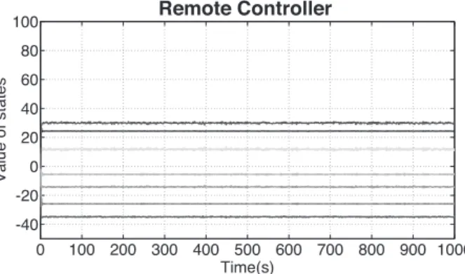
We present in Figure 4 the dynamic of the plant and how the adversary can modify this dynamic to disrupt the system. Figure 5 shows how the detectors present in the sensors are able to detect attacks using the periodical communication policy and a watermark managed by sensors. Figure 5A,B shows the dynamic of the states estimated by the local controllers placed in sensors and the remote controller placed in control center, respectively. Figure 5C,D shows the dynamic of the alarm in sensors (local detectors) and in the control center (remote detector). We show in these Figures an attack, which is detected by the local detectors, but whose alarm's dynamic is not transmitted to the control center. The sensors' alarms are stopped by a cyber-physical adversary that takes the control of the system and sends a dynamic alarm correlated with the data sent from the remote controller (control center) to the actuator. This action allows the adversary attack the system without be detected.
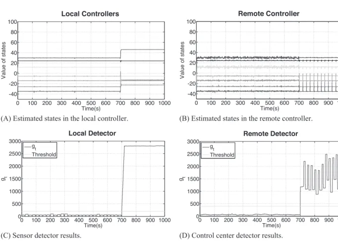
Figure 6 presents the control/security strategy using the periodical and intermittent communication policies. As shown in Figure 6, it is visible that using both policies allows the system to detect the attack. Figure 6C shows the local detector that is able to detect a disruption in the dynamic of the plant, thanks to the periodical communication policy. In Figure 6D, we can see that the remote detector (placed in the control center) is able to detect that the closed loop is broken, using the remote controller's watermark and the intermittent communication policy.
Our strategy handles integrity attacks at the physical level, by using the watermark sent by the local controller, ie, placed in the sensors (cf Figure 6A), as well as integrity attacks carried out through the network, via the closed-loop verification conducted by the remote controller, using stochastic metrics to trigger the watermark (cf Figure 6B). The states estimated by the local and remote controllers (cf Figure 6A,B) are handled and mitigated by the system, reporting the events to security operators (eg, in terms of alerts) and activating the appropriate corrective mechanisms.
(A) Estimated states in the local controller. (B) Estimated states in the remote controller.
(C) Sensor detector results. (D) Control center detector results.
FIGURE 5 Numeric simulation results, using only periodical policy. Attacks start at t = 700s. A,B, The dynamics of the states vector estimated in the local and remote controller, respectively, under the same scenarios. C,D, The dynamics of the alarm signal gtproduced in the local and remote
detector, respectively, under the same scenarios
6
E X P E R I M E N T A L R E S U L T S
We present some experimental results obtained with a laboratory testbed. The testbed implements the detection strategy and the adversary models presented in this paper. The implementation is conducted using Modbus30and DNP3,312 well-known
SCADA protocols used in cyber-physical industrial systems.
6.1
SCADA Testbed
SCADA is a general term that encompasses well-defined types of field devices, such as: (1) master terminal units and human machine interfaces, located at the topmost layer and managing all communications; (2) remote terminal units (RTUs) and programmable logic controllers (PLCs), controlling and acquiring data from remote equipment and connecting with the master stations; and (3) sensors and actuators.
The design of our testbed includes all those aforementioned field devices: controllers, sensors, actuators, PLCs, and RTUs. The devices are distributed across several nodes in a shared network combining Modbus30 and DNP3.31One or various field
devices can be embedded into a single node. From a software standpoint, the controller never connects directly to the sensors. Instead, it is integrated in the testbed as a PLC node, with eventual connections to some other intermediary nodes. To run our experiments, we created a distributed network where the control center communicates with the physical devices through the RTUs. The communication between the control center and the RTUs uses the protocol DNP3 and the communication between the RTUs and the physical devices uses Modbus. The testbed can be expanded to handle additional SCADA protocols, as well as to connect complementary devices, such as additional PLCs and RTUs.
From a data transmission standpoint, the devices connected to the testbed use different sampling frequencies. The testbed is able to handle several PLCs. To avoid overloading 1 channel with all the possible registers of the PLCs, different ports are designated to isolate the communication between separated PLCs. DNP3 commands perform an integrity scan that gathers all the data from the PLCs in case several PLCs were being handled in the same channel. This avoids variables of the PLCs causing communication overheads.
14 of 17
(A) Estimated states in the local controller. (B) Estimated states in the remote controller.
(C) Sensor detector results. (D) Control center detector results.
FIGURE 6 Numeric simulation results, using periodical and intermittent policies. Attacks start at t = 700s. A,B, The dynamics of the states vector estimated in the local and remote controller, respectively, under the same scenarios. C,D, The dynamics of the alarm signal gtproduced in the
local and remote detector, respectively, under the same scenarios
FIGURE 7 Cyber-physical industrial scenario implemented in our experimental testbed. The 2 mobile agents, represented by solid and pattern gray squares, move from and toward 2 spatial coordinates, represented by solid and pattern gray circles. Some live demonstration videos of this setup are available at http://j.mp/TSPScada
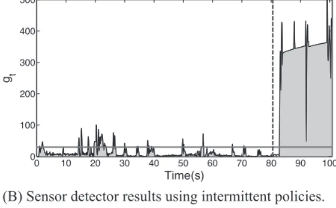
(A) Sensor detector results not using intermittent policy. (B) Sensor detector results using intermittent policies.
(C) Control center detector results not using intermittent policy.
(D) Control center detector results using intermittent policy.
FIGURE 8 Experimental testbed results. The horizontal solid line represents the threshold. The vertical dotted line represents the moment when the attack starts. Peaks on the left side of the vertical dotted line represent false positives. A,B, Local detector values gt(placed within the sensors)
without and with intermittent policies (ie, remote watermarks) under a parametric attack. C,D, Remote detection values (placed at the control center) without and with intermittent policies under a parametric attack
A sample cyber-physical industrial scenario implemented in our testbed is shown in Figure 7. In the Figure, the solid and pattern gray squares represent 2 mobile agents that move from 2 spatial coordinates (represented by the the solid and pattern gray circles), and vice versa. Each mobile agent controls the dynamics of its movements. The 2 agents are coordinated by a SCADA controller, to avoid spatial collisions. Further information, as well as some live demonstration videos, is available at http://j.mp/TSPScada.
6.2
Experimentation and results
We present the results of applying the detection strategy, assuming attackers under the parametric adversary model. The attacker tries to evade the detection techniques reported in this paper. In a first scenario, the system uses only a periodic communi-cation policy using the watermark detector placed at the sensors (cf Figure 8A,C). When the attacker successfully infers the system parameters, the attack is not reported by the remote controller. Nevertheless, local alarms placed at the sensors report the attack. In a second scenario, the system uses also the intermittent policy. In such a case, the attack is detected (cf Figure 8B,D) by the remote controller. In Figure 8B, we may observe some peaks (cf, t = [2.1s; 14.4s; 15.3s; 17.6s; 20.4s; 21.0s; 22.3s; 26.2s; 37.8s; 56.8s; 66.8s]), representing the local detector's reaction in the presence of a watermark sent by the remote controller — used to verify that the closed loop works properly, as defined in Section 4.3.
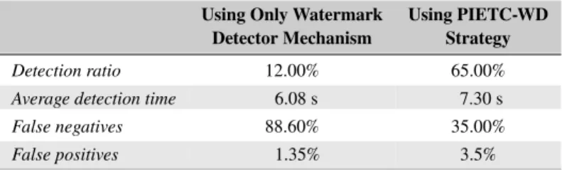
To compare the watermark-based detector mechanism and our detection strategy, several repetitions of the experiment were orchestrated. Using the results obtained from the testbed experiments, we report in Table 3 the percentage of false positives, false negatives, and detection ratio. We also show the average time that the detector placed at the control center, takes to launch the alerts. Notice that the workload in the sensors, due to adding the local controller in our detection strategy, does not significantly increase the performance loss of the system. The increase, in terms of memory and processing time, is shown in Table 2.
Regarding the results shown in Table 3, we can emphasize that: (1) a system that uses only the watermark-based detector mechanism against a parametric attacker has a lower detection ratio, of about 12%. That is possible since the attacker can evade
16 of 17 RUBIO-HERNANET AL.
TABLE 2 Memory and processing time increase, due to the PIETC-WD strategy implementation
Time RAM Memory
Sensor's workload increase 17.13 ms 5.23%
Abbreviation: PIETC-WD, periodic and intermittent event-triggered control watermark detector.
TABLE 3 Detector performance results
Using Only Watermark Using PIETC-WD
Detector Mechanism Strategy
Detection ratio 12.00% 65.00%
Average detection time 6.08 s 7.30 s
False negatives 88.60% 35.00%
False positives 1.35% 3.5%
Abbreviation: PIETC-WD, periodic and intermittent event-triggered control watermark detector.
the detection process if they succeed at properly identifying the system attributes. This result is expected, as suggested by the theoretical and simulation-based conclusions presented in the work of Rubio-Hernan22; and (2) a system that uses the strategy
proposed in this paper has a higher detection ratio, of about 65.00%. In this scenario, the detection ratio increases, thanks to the distributed detector proposed in Section 4, confirming the theoretical and simulation-base result reported in the previous sections. Moreover, the false negative ratio significantly decreases, from 88.60% to 35.00%. In terms of false positives, both scenarios show similar data, but the PIETC-WD strategy generates about 2.0% more. The time between the beginning of the attack and the moment, when the attack is detected by the remote controller, also increases, since the detection watermark managed by the remote controller follows a stochastic law.
7
C O N C L U S I O N
We have addressed security issues in cyber-physical industrial systems. We have presented an adaptive strategy that detects adversaries that are able to acquire knowledge about the system dynamics, prior to starting their attacks to get control over the inputs and measurements of the system. In addition to industrial systems, any other cyber-physical scenario, modeled in terms of sensors, actuators and feedback control, can benefit from the approach. Computer networks complemented by physical systems, such as Internet of things scenarios, may also benefit from the approach. We have validated the construction using numerical validation and a laboratory testbed based on SCADA industrial protocols. We have shown that the strategy is able to detect the attacks with a high detection ratio.
A C K N O W L E D G E M E N T S
The authors acknowledge support from the Cyber CNI Chair of the Institut Mines-Télécom (cf http://chaire-cyber-cni.fr/). The chair is supported by Airbus Defence and Space, Amossys, EDF, Orange, La Poste, Nokia, Société Générale and the Regional Council of Brittany. It has been acknowledged by the Center of excellence in Cybersecurity.
R E F E R E N C E S
1. Hespanha JP, Naghshtabrizi P, Xu Y. A survey of recent results in networked control systems. Proc IEEE. 2007;95(1):138-162. https://doi.org/ 10.1109/JPROC.2006.887288
2. Kim KD, Kumar PR. Cyber-physical systems: a perspective at the centennial. Proc IEEE. 2012;100:1287-1308. https://doi.org/10.1109/JPROC. 2012.2189792
3. Wu G, Sun J, Chen J. A survey on the security of cyber-physical systems. Control Theory Technol. 2016;14(1):2-10. https://doi.org/10.1007/ s11768-016-5123-9
4. Falliere N, Murchu LO, Chien E. W32 stuxnet dossier. White paper, Symantec Corp, Security Response. 2011;5:6.
5. Weyer S, Schmitt M, Ohmer M, Gorecky D. Towards industry 4.0 - Standardization as the crucial challenge for highly modular, multi-vendor production systems. IFAC-PapersOnLine. 2015;48(3):579-584. https://doi.org/10.1016/j.ifacol.2015.06.143
6. Lee J, Bagheri B, Kao HA. A cyber-physical systems architecture for industry 4.0-based manufacturing systems. Manuf Lett. 2015;3:18-23. https://doi.org/10.1016/j.mfglet.2014.12.001
7. Salt J, Casanova V, Cuenca A, Pizá R. Sistemas de control basados en red modelado y diseño de estructuras de control. Revista Iberoamericana de Automática e Informática Industrial RIAI. 2008;5(3):5-20. https://doi.org/10.1016/S1697-7912(08)70157-2
8. Heemels W, Donkers M, Teel AR. Periodic event-triggered control for linear systems. IEEE Trans Autom Control. 2013;58(4):847-861. https:// doi.org/10.1109/TAC.2012.2220443
9. Han D, Mo Y, Wu J, Weerakkody S, Sinopoli B, Shi L. Stochastic event-triggered sensor schedule for remote state estimation. IEEE Trans Autom Control. 2015;60(10):2661-2675. https://doi.org/10.1109/TAC.2015.2406975
10. Corman D, Pillitteri V, Tousley S, Tehranipoor M, Lindqvist U. NITRD cyber-physical security panel. Paper presented at: 35th IEEE Symposium on Security and Privacy, IEEE SP 2014, May 18-21, 2014; San Jose, CA, USA.
11. Mo Y, Garone E, Casavola A, Sinopoli B. False data injection attacks against state estimation in wireless sensor networks. Paper presented at: 49th IEEE Conference on Decision and Control (CDC); 2010; Atlanta, GA, USA. https://doi.org/10.1109/CDC.2010.5718158
12. Smith RS. Covert misappropriation of networked control systems: presenting a feedback structure. IEEE Control Syst. 2015;35(1):82-92. https:// doi.org/10.1109/MCS.2014.2364723
13. Mo Y, Weerakkody S, Sinopoli B. Physical authentication of control systems: designing watermarked control inputs to detect counterfeit sensor outputs. IEEE Control Syst. 2015;35(1):93-109. https://doi.org/10.1109/MCS.2014.2364724
14. Teixeira A, Shames I, Sandberg H, Johansson KH. A secure control framework for resource-limited adversaries. Automatica. 2015;51:135-148. https://doi.org/10.1016/j.automatica.2014.10.067
15. Pasqualetti F, Dorfler F, Bullo F. Cyber-physical security via geometric control: Distributed monitoring and malicious attacks. Paper presented at: 2012 IEEE 51st IEEE Conference on Decision and Control (CDC); 2012; Maui, HI, USA. https://doi.org/10.1109/CDC.2012.6426257 16. Mo Y, Sinopoli B. Secure control against replay attacks. Paper presented at: Proceedings of the 47th Annual Allerton Conference on
Communication, Control, and Computing. IEEE; 2009; Monticello, IL, USA. https://doi.org/10.1109/ALLERTON.2009.5394956
17. Miao F, Pajic M, Pappas GJ. Stochastic game approach for replay attack detection. Paper presented at: Proceedings of the 52nd IEEE Conference on Decision and Control; 2013; Florence, Italy. https://doi.org/10.1109/CDC.2013.6760152
18. Zhu Q, Ba¸sar T. Dynamic policy-based IDS configuration. Paper presented at: Proceedings of the 48th IEEE Conference on Decision and Control CDC) held jointly with 2009 28th Chinese Control Conference; 2009; Shanghai, China. https://doi.org/10.1109/CDC.2009.5399894
19. Do VL, Fillatre L, Nikiforov I. A statistical method for detecting cyber/physical attacks on SCADA systems. Paper presented at: Proceedings of 2014 IEEE Conference on Control Applications (CCA); 2014; Juan Les Antibes, France. https://doi.org/10.1109/CCA.2014.6981373
20. Genge B, Kiss I, Haller P. A system dynamics approach for assessing the impact of cyber attacks on critical infrastructures. Int J Critical Infrastruct Prot. 2015;10:3-17. https://doi.org/10.1016/j.ijcip.2015.04.001
21. Rubio-Hernan J, De Cicco L, Garcia-Alfaro J. Revisiting a watermark-based detection scheme to handle cyber-physical attacks. Paper presented at: Proceedings of the 11th International Conference on Availability, Reliability and Security. IEEE; 2016; Salzburg, Austria.
22. Rubio-Hernan J, De Cicco L, Garcia-Alfaro J. Event-triggered watermarking control to handle cyber-physical integrity attacks. Paper presented at: Proceedings Secure IT Systems: 21st Nordic Conference, Nordsec 2016, Oulu, Finland, November 2-4, 2016; Springer International Publishing: Cham. https://doi.org/10.1007/978-3-319-47560-8_1
23. Wang Y, Xu Z, Zhang J, Xu L, Wang H, Gu G. SRID: State relation based intrusion detection for false data injection attacks in SCADA. In: Kutyłowski M, Vaidya J, eds. Computer Security - Esorics 2014: 19th European Symposium on Research in Computer Security, Wro-claw, Poland, September 7-11, 2014. Proceedings, Part II. Cham: Springer International Publishing; 2014:401-418. https://doi.org/10.1007/ 978-3-319-11212-1_23
24. Arvani A, Rao VS. Detection and protection against intrusions on smart grid systems. Int J Cyber Secur Digit Forensics (IJCSDF). 2014;3(1):38-48.
25. Baheti R, Gill H. Cyber-physical systems. Impact Control Technol. 2011;12:161-166.
26. Heemels W, Donkers M. Model-based periodic event-triggered control for linear systems. Automatica. 2013;49(3):698-711. https://doi.org/10. 1016/j.automatica.2012.11.025
27. Brumback B, Srinath M. A chi-square test for fault-detection in Kalman filters. IEEE Trans Autom Control. 1987;32(6):552-554. https://doi.org/ 10.1109/TAC.1987.1104658
28. Franklin GF, Powell JD, Workman ML. Digital control of dynamic systems. 3rd ed. Boston, MA, USA: Addison-Wesley Longman Publishing Co., Inc.; 1998.
29. Natke HG. System identification: Torsten Söderström and Petre Stoica. Automatica. 1992;28(5):1069-1071.
30. Modbus Organization. Official Modbus Specifications. http://www.modbus.org/specs.php. 2016. Accessed: March 2017.
31. Curtis K. A DNP3 protocol primer. A basic technical overview of the protocol. http://www.dnp.org/AboutUs/DNP3%20Primer%20Rev%20A. pdf. 2005. Accessed: March 2017.