HAL Id: hal-01600116
https://hal.archives-ouvertes.fr/hal-01600116
Submitted on 3 Jul 2018
HAL is a multi-disciplinary open access
archive for the deposit and dissemination of sci-entific research documents, whether they are pub-lished or not. The documents may come from teaching and research institutions in France or abroad, or from public or private research centers.
L’archive ouverte pluridisciplinaire HAL, est destinée au dépôt et à la diffusion de documents scientifiques de niveau recherche, publiés ou non, émanant des établissements d’enseignement et de recherche français ou étrangers, des laboratoires publics ou privés.
Massive antenna array for space time channel sounding
Patrice Pajusco, François Gallée, Nadine Malhouroux-Gaffet, Roxana
Burghelea
To cite this version:
Patrice Pajusco, François Gallée, Nadine Malhouroux-Gaffet, Roxana Burghelea. Massive antenna array for space time channel sounding. EUCAP 2017 : 11th European conference on antennas and propagation, Mar 2017, Paris, France. pp.865 - 868, �10.23919/EuCAP.2017.7928631�. �hal-01600116�
Massive Antenna Array for
Space-Time Channel Sounding
P. Pajusco1, F. Gallée1, N. Malhouroux2, R. Burghelea1
1 Lab-STICC - Institut Mines-Télécom - Télécom Bretagne, Brest, France, [email protected]
2 Orange Labs - Belfort (Orange)
Abstract—In this paper, a prototype of a dual-polarized array antenna is presented. This array was designed in the framework of a collaborative project on spatial modulation schemes. It will be used for the project testbed and for space-time channel measurements. This array features several novelties, including a slant uniform planar structure, a scalable design with integrated switching circuitry, a reference antenna and a camera. The array has been successfully used with a wideband channel sounder to provide real-time radio photos.
Index Terms—antenna array, channel sounding, direction of arrival, massive MIMO.
I. INTRODUCTION
Wideband channel models should be realistic and should include all physical effects of the propagation channel, e.g. transmitter (TX) and receiver (RX) spatial spreading, temporal spreading, depolarization, etc. This is especially important in the context of advanced transmission schemes, such as massive MIMO or spatial modulation. System performance can be investigated using various massive MIMO testbeds, most of which are recapped in the first tables of [1] and [2]. The number of antennas ranges from 32 to 128. Such testbeds are quite complex due to large number of transceivers. Alternatively, spatial modulation [3] is a promising modulation scheme but deeper investigation is needed. It involves carrying the symbol information by choosing a specific antenna of a massive array. Consequently, only a single transmitter is needed to simplify the communication system. However, the array is a bit more complex because it has to include the RF switch circuitry. Such antenna arrays can also be used in propagation channel measurement.
For accurate MIMO channel modeling, it is important to estimate path directions in azimuth and elevation, along with the amplitude and polarization of waves on both sides of the link. The characteristics of the array play a major role in the final performance irrespective of the algorithm used (e.g. casual beam former or advanced high-resolution techniques) [4], [5]. In this paper, the design of a massive antenna array is presented which would be further used in the spatial modulation testbed as well as MIMO channel measurements.
The first section introduces the design of the antenna array. The real prototype is discussed in the second section. Finally, two examples of use are provided: one in an anechoic chamber
for validation purpose and one in indoor environment for real-time radio photo demonstration.
II. ANTENNA ARRAY DESIGN
a) Introduction
Various antenna solutions based on the switching approach have been proposed with different configurations and in different frequency bands. For MIMO channel modeling, the knowledge of the polarization state is also important. For instance, dual-polarization patch antennas are used in a Uniform Planar Array (UPA) [6] and a Uniform Circular Array (UCA) [7].
Our challenge was to design an easy-to-use, flexible, portable antenna array. The main idea was to co-integrate the antennas, feeding network and switching matrix. The main specifications are recapped hereafter:
• Flexible number of antennas • Integrated switching matrix • Dual polarizations
• θ and ϕ scanning capability (post processing) • Single RF access
• Control command for antenna selection • LTE frequency
b) Array geometry
In order to steer the beam in both azimuth and elevation, a planar array can be used as the simplest solution. Compared to a circular or spherical array, this geometry limits the array field of view to about ±60°. However, this is representative of a base station in a 120° sector cellular configuration. For the ease of prototyping, printed technology was chosen for the array elements. To maximize the field of view of each element, slot radiating elements were selected in contrast to patch radiating elements.
UPA is defined by a rectangular shape with uniform
spacing of λ/2. An example with 25 vertical slot antennas is
shown in Fig. 1a. We propose to introduce Slant Uniform
Planar Array (SUPA). An example of 25 SUPA elements is depicted in Fig. 1b. With the same element number and spacing between them, this structure is wider along both the x and y axes. If we consider only the Uniform Linear Array (ULA) for y=0, the beam resolution in the horizontal plane is improved. For y≠0, the different horizontal ULAs are smaller
and the beam resolution is lower. If all elements are fed, this acts as a window effect and reduces side lobes. These properties are illustrated in Fig. 2 for two different beam steering angles. Compared to classic UPA, SUPA makes it possible to reduce side lobes with the same beamwidth. It is also possible to improve the angular resolution in the horizontal plane. Based on these improved characteristics, the SUPA geometry was chosen. Horizontal slot radiating antennas were interleaved to get a dual-polarized array.
a) 5×5 UPA b) 25 SUPA Fig. 1 : Array geometry
a) Beam angle phi = 0° b) Beam angle phi = 30° Fig. 2 : Beam characteristics of the UPA and SUPA
c) Scalable design
Massive MIMO systems use a large number of antennas. According to [1-2], the number of antennas varies from 32 to 128. In spatial modulation, the number of antennas is also important because it represents the spatial state number of the modulation. To anticipate future application needs, we designed a structure which makes it possible to easily increase the number of antennas. For that purpose, a small array was designed as a LEGO™ brick, and the structure is depicted in 3a. This brick can be combined to obtain an arbitrary number of elements as depicted in 3b-c.
d) Elementary module
The elementary brick is an array of 16 slot antennas (8 in vertical polarization and 8 in horizontal polarization) with a
uniform spacing of λ/2 (Fig. 4a). The motivation behind the
choice of the slot is the requirement of a low-directivity elementary antenna allowing scanning or beamforming over a wider angle. The main constraint is to ensure a similar phase shift for each antenna. The adopted solution is to distribute the switch matrix on several levels by using an SP4T switch (Fig. 4b). For a simple RF circuit, a phase shift of 180° is introduced due to the position of the slot antenna excitation. This will be corrected by the system calibration. The DC power supply and the control of the switches are distributed on a PCB behind the antenna PCB (Fig. 5). The PCB in
question is located at λ/4 of the antenna PCB to act like a
reflector of the slot antenna.
a) 16 elements b) 64 elements c) 256 elements Fig. 3 : Scalable SUPA
Slot radiating element Switchs SP4T H pol V pol
a) Antenna face b) Electronic face Fig. 4 : Core module
Coaxial cable UFL-SMA
Plastic radom Antenna PCB
DC control and reflector plane PCB
TTL control and power supply connector Switch SP4T 4 λ
Fig. 5 : The final elementary module
e) Module Assembly
The flexible geometry antenna is simply built from the association of several elementary bricks as shown in the Fig. 3. To simplify post-processing, the radiation patterns of all the slots should be similar. However, the radiation is disturbed by the adjacent slots due to the coupling effect. Electromagnetic simulation showed that a minimum of two slots on each side is required to avoid border effects. For this reason, two rows of dummy slots were added. Absorptive switches were chosen to reduce the fringing field effect.
III. ANTENNA PROTOTYPE
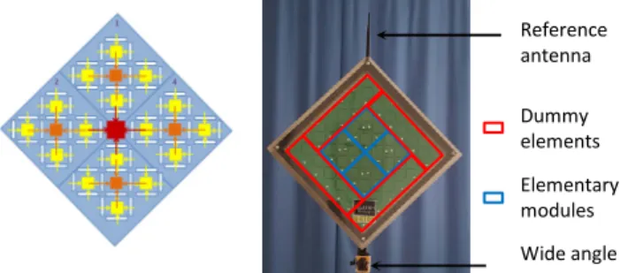
The frequency band chosen is 3.6-3.8 GHz corresponding to an LTE allocated frequency band. This prototype, depicted in Fig. 6, was built with four elementary modules, e.g. 64 switched slot radiating elements (32 for horizontal polarization and 32 for vertical polarization). The first layer, in red, is composed of one SP4T switch to select the module. The second layer, in orange, is composed using four SP4T switches and the third layer, in yellow, with sixteen SP4T switches.
For accurate direction of arrival estimation, the 64 slot antennas’ radiation patterns were characterized in 3D thanks to the SG 32 equipment from MVG Company. The antenna array being tested is depicted in Fig. 7. This measurement includes phase calibration of the integrated switch matrix.
Reference antenna Wide angle camera Elementary modules Dummy elements
a) Switch matrix layer b) Picture of the Final prototype Fig. 6 : The antenna prototype
Fig. 7 : 3D radiation pattern calibration
Environment configuration is very important in propagation channel measurements, especially in the case of dynamic scenarios. Thus, it is really convenient to get a continuous view of the environment seen by the antenna. For that purpose, a wide angle camera was included in the antenna array. The SP360 from Kodak™ was selected because it offers a wide enough field of view (+/-120° in azimuth and elevation). Moreover, the MJPEG live stream is easy to get and included in real time for channel sounder application.
IV. DIRECTION OF ARRIVAL ASSESSMENT
a) Direction of arrival estimation
A traditional method of beamforming was used [8]. While this method suffers from poor angular resolution, it does offer linear, robust behavior. This method is also faster (no search values, no iterative process) than high-resolution techniques. The principle is recapped briefly in case of a narrow band signal. The different received signals are stored in the vector
[
1, , ,...,2 3]
T nx= x x x x where x represents the received signal i
on the ith antenna. The antenna array response in direction
( , )θ ϕ is defined by the vector
[
1 2 3]
( , ) ( , ), ( , ), ( , ),..., ( , )n T
aθ ϕ = a θ ϕ a θ ϕ a θ ϕ a θ ϕ
where ai( , )θ ϕ is the far field gain of the ith antenna. The
weighting vector
w
( , )
θ ϕ
to steer in direction ( , )θ ϕ isdefined by * ( , ) ( , ) ( , ) a w a θ ϕ θ ϕ θ ϕ
= . To improve sidelobe levels, a
2D weighting window may be applied, but it will also increase the beamwidth. The computation of direction of arrival in 2D is obtained simply by beaming in the different directions.
b) Validation in an anechoic environment
Validation was carried out in an anechoic chamber using a VNA and Matlab™ for post-processing. The TX antenna was a path antenna. The measurement set-up is detailed in Fig. 8. To validate the measurements of the direction of arrival, the TX antenna was located at various distances and angles from the RX. Fig. 9 presents two configurations of the TX antenna (TA and TB). Fig. 10 shows the DoA (Direction of arrival) estimate from the method described in section IIIa for position TA. The blue ellipse represents the E field trajectory, i.e. it provides information on the polarization state in the direction of the maximum. In this case, the polarization is nearly vertical (XPD>20dB), which is in accordance with the patch orientation. Radio channel VNA Radio feeder Radio feeder USB Ethernet Analysis and storage
Fig. 8 : Equipment set-up
TB RX TB h=0.78m RX Anechoïc chamber TA h=1.35m
a) RX array b) TX patch c) Reference locations Fig. 9 : Measurement configuration
Fig. 10 : Direction of arrival assessment for position TA TABLE I. Position TA TB Beamforming Azimuth 18° 28° Elevation 89° 100° Geometrical Azimuth 21.7° 33° Elevation 90° 103.9°
Table I compares the estimated direction (beamforming method) and the geometrical measured direction in the azimuth and elevation planes. Both positions present a good agreement between the actual LOS direction and the estimated direction from the beamforming method.
c) Real-time radio-photo application
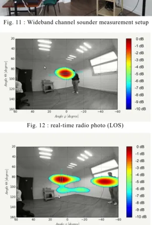
The slant uniform planar array was used with Telecom Bretagne’s real-time MIMO wideband channel sounder. This equipment is depicted in Fig. 11. The transmitter is composed of an arbitrary wave form generator and a patch antenna, and the channel sounder is based on a real-time SDR platform. Antenna switching is performed by the FPGA, and real-time acquisition is performed in C++. Finally, DoA estimation and video merging are performed in Python. In this example, the antenna array prototype was used in LOS condition. The user holds the patch antenna. Fig. 12 and Fig. 13 represent the radiophoto for two configurations.
Transmitter Channel
sounder
Fig. 11 : Wideband channel sounder measurement setup
-10 dB -9 dB -8 dB -7 dB -6 dB -5 dB -4 dB -3 dB -2 dB -1 dB 0 dB
Fig. 12 : real-time radio photo (LOS)
-10 dB -9 dB -8 dB -7 dB -6 dB -5 dB -4 dB -3 dB -2 dB -1 dB 0 dB
Fig. 13 : real-time radio photo (LOS + reflected path)
In Fig. 12, the user holds the patch horizontally in front of the array. As a result, the polarization of the received path is nearly horizontal, as represented by the horizontal ellipse. In Fig. 13, the user location is far from the array boresight and, additionally, the antenna is oriented towards the opposite wall. The array is able to identify both the direct and the reflected paths. A short video of this test is available on [9].
V. CONCLUSION AND FUTURE WORK
The design of a dual-polarized array antenna was presented in this paper. A slant uniform array structure was proposed to improve side lobe levels. The proposed concept makes it possible to design an array with a scalable antenna beamwidth, depending on the number of antennas. The concept was evaluated by building a 64-element prototype in the LTE frequency bands. Calibration and validation were performed in an anechoic chamber. Finally, the array was successfully used with a channel sounder to estimate in real time the polarization and direction of arrival in LOS configuration. Results were shown on radiophoto.
Future work will use the antenna array in indoor and outdoor environments to get new channel measurements in different settings and contribute to the improvement of massive MIMO propagation modeling. High resolution algorithms will be also implemented to increase the DoA estimate accuracy.
ACKNOWLEDGMENT
The authors wish to thank the MVG Company for access to the SG 32 facilities. They also acknowledge the financial support of the “Agence National de la Recherche” who funded the “spatial modulation” collaborative project in which this work was partly done.
[1] P. Harris, S. Zhang, M. Beach, E. Mellios, A. Nix, S. Armour, A. Doufexi, K. Nieman, N. Kundargi, “LOS Throughput Measurements in Real-Time with a 128-Antenna Massive MIMO Testbed”, Cost Action n°15104, Lille, june 2016
[2] J. Vieira et al., "A flexible 100-antenna testbed for Massive MIMO,"
2014 IEEE Globecom Workshops (GC Wkshps), Austin, TX, 2014, pp.
287-293.
[3] M. D. Renzo, H. Haas, A. Ghrayeb, S. Sugiura, and L. Hanzo, “Spatial modulation for generalized MIMO: Challenges, opportunities, and implementation,” Proceedings of the IEEE, vol. 102, pp. 56–103, Jan. 2014.
[4] F. Rusek et al., "Scaling Up MIMO: Opportunities and Challenges with Very Large Arrays," in IEEE Signal Processing Magazine, vol. 30, no. 1, pp. 40-60, Jan. 2013.
[5] J. Choi, T. Kim, D. J. Love and J. y. Seol, "Exploiting the preferred domain of FDD massive MIMO systems with uniform planar arrays,"
2015 IEEE International Conference on Communications (ICC),
London, 2015, pp. 1465-1470.
[6] P. Tang, J. Zhang, Y. Sun, M. Zeng, Z. Liu and Y. Yu, "Clustering in 3D MIMO Channel: Measurement-Based Results and Improvements,"
Vehicular Technology Conference (VTC Fall), 2015 IEEE 82nd,
Boston, MA, 2015, pp. 1-6.
[7] R. Müller et al., "Design of a circular antenna array for MIMO channel sounding application at 2.53 GHz," The 8th European Conference on
Antennas and Propagation (EuCAP 2014), The Hague, 2014, pp.
239-243.
[8] Xiang Gao; Edfors, O.; Rusek, F.; Tufvesson “Massive MIMO Performance Evaluation Based on Measured Propagation Data”, Wireless Communications, IEEE Transactions, Year: 2015, Volume: 14, Issue: 7