Reduced span spray: Part 3: Design of a narrow span
nozzle
By N DE COCK, S OULED TALEB SALAH, M MASSINON and F LEBEAU
University of Liège (ULg), Gembloux Agro-Bio Tech (GxABT) Corresponding Author Email: nicolas.decock@student.ulg.ac.be
Summary
Optimization of the droplet spectra of the agricultural spray may increase the spray application efficiency. The optimal spray would contain only the most efficient droplets in term of speed and size. Therefore, this paper is presenting the first steps of the design of a narrow span nozzle in order to produce an optimized spray. The starting geometry is a splash plate nozzle with a disk ending with structures (i.e. tooth, grooves, and needles) that would separate the liquid sheet into jets. These jets would be in the Rayleigh regime which has the advantage of producing narrower droplet spectra than liquid sheet break-up.
The present project aims to design a hydraulic nozzle producing a spray with a narrow drop size distribution in order to increase the agricultural spray application efficiency. In the present paper the first project steps are presented.
Key words: Agricultural spray, drop size distribution, hydraulic nozzle, Rayleigh
break-up, CFD
Introduction
Spray application is a key process in crop protection to ensure that high yields are obtained while minimizing adverse environmental and health impact of plant protection products. During this process, the agricultural mixture is fragmented by passing through a nozzle generating a cloud of droplets. It has been proved that the droplet size distribution of the spray significantly affects the global deposition process efficiency (Matthews, 2008). Indeed, smaller droplets have a higher drift potential (Taylor P et al., 2004) leading to potential product losses in air, water and soil (Reichenberger et al., 2007). Whilst, larger droplets, with a higher kinematic energy, are more prone to splash while impacting the target and then may reduce the plant retention efficiency (Massinon & Lebeau, 2012). Therefore, an ideal agricultural spray would include only medium size droplets, i.e. ranging between 200 and 300 µm for weed treatment. The droplet sizes and speeds constitutive of a spray result from the interactions between physical properties of the liquid, the operating conditions and the nozzle geometry (Miller & Ellis, 2000). During the past decades, multiple researches have been performed on the effect of the liquid physical properties (Ellis et al., 1997; Ellis et al., 2001; Holloway et al., 2000) as well as the nozzle type (Nuyttens et al., 2007). The need of a narrow drop size distribution stimulated the development of devices for spray
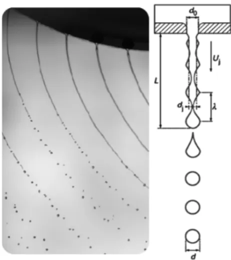
generation using centrifugal forces such as the rotary atomizers. These atomizers produce a significantly narrower drop size distribution than the hydraulic nozzles usually used in agriculture. Despite the quality of the produced sprays, the rotary atomizers are hardly used for field spray application because of their bulkiness. However, they remain an interesting study case as a way to produce sprays with narrow drop size distribution. The contrast in the drop size distribution between the hydraulic nozzles and the rotary atomizers derives from the different breakup modes occurring with the two atomizers types. Rotary atomizers produce round liquid jets of uniform sizes at the exit of the rotating part, then the jets break in droplets by the Rayleigh-Plateau mode (Fig. 2). Whilst, the hydraulic nozzles produce a liquid sheet that break-up in ligaments which, in turn, break-up in to droplets of various sizes (Fig. 1).
Figure 1. Illustration of the breakup mode occurring at the exit of a hydraulic nozzle.
Figure 2. Illustration of the breakup mode occurring at the exit of a rotary atomizer.
The Rayleigh-Plateau breakup regime occurs when a cylindrical jet is discharged into gas with a low inertia in respect with its capillary forces. Therefore the Weber number is used as criterion to set the limits of the Rayleigh-Plateau regime (Dumouchel, 2008). The liquid Weber number WeL has to be higher than 8 and the gaseous Weber number WeG has to be lower than 0.4. With WeG and WeL defined as:
σ d U ρ = We σ d U ρ = We L L G g L L 2 2
where ρL and ρG are the liquid and the gas density respectively, UL is the liquid speed, d is the jet diameter and σ is the surface tension.
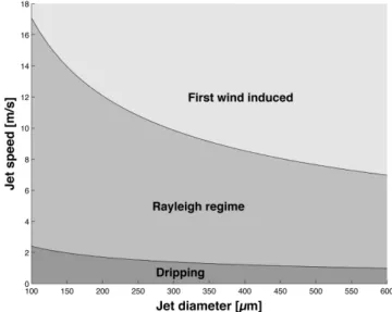
These Weber numbers correspond to low Reynolds and Ohnesorge numbers. Theoretical developments realized by Rayleigh (Strutt & Rayleigh, 1878) showed that the growth of the most unstable perturbation breaks the jet in droplets of 1.89 times the jet diameter. Therefore the jet breakup can be controlled by triggered by stimulating the most unstable wavelength, e.g. using acoustic waves generated by piezoelectric element with the adequate wavenumber (Brenn & Lackermeier, 1997; Brenn et al., 1996). The Rayleigh break-up domain correspond to low speed
and jet size as shown on the figure 3 for the case of a water jet discharging in air. This diagram shows that using the Rayleigh break-up regime, droplets of 300µm with a speed of 13 m/s can be produced.
Figure 3. Breakup regimes of a cylindrical water jet in air at atmospheric pressure. Goals
The present project aims to design a hydraulic nozzle producing a spray with a narrow drop size distribution in order to increase the agricultural spray application efficiency. The starting design of this nozzle will be a splash plate nozzle for which the plate will be modified in order to split the liquid sheet formed on the plate into multiple jets at its end. The jets would be in Rayleigh regime and then generate a narrow drop size distribution. For agricultural spraying the common flow rate is around 1 l/min and the droplet diameter would be ranging between 250-300 µm. Thus, it requires roughly 60 to 90 jets with a speed of 10 to 15 m/s in order to deliver the adequate flow rate. The present paper is presenting the first steps of this project.
Nozzle geometry description
The splash plate nozzle geometry can be simplified as a pipe ending perpendicularly on a horizontal disk. The flow will create a liquid sheet on the disk then at the exit of the disk a liquid sheet or multiple jets will be formed.
Three main regions of the nozzle can be distinguished: the nozzle pipe end, the disk, the disk border. In the two first regions the objective will be to generate a homogeneous flow with the right properties in term of speed and thickness. Then at the disk border specific structures (teeth, grooves, and channels) will be used in order to separate the liquid sheet in to multiple jets.
Nozzle pipe
One requirement of the nozzle design is to obtain at the end of the disk a homogeneous liquid sheet making an angle of 140°. Over 140°, there is a gap of 0.3 mm between the plate and the pipe. This opening guides the flow parallel to the plate. Numerical simulations realized on OpenFOAM with the volume of fluid solver InterFOAM (De Cock et al., 2014). Two pipes geometries have been
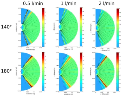
tested a circular segment with an opening of 140° or 180°. For both geometries, three flow rates are tested: 0.5, 1 and 2 liters per minute. The figure 4 presents the spatial distribution of the normalized water flow rate in the radial direction. The flow is normalized at each position by the inlet flow and the distance from the inlet center. Therefore, for an ideal case the flow rate would be 1 between 0° and 70°. For all the cases, the water flows radially in respect with the inlet. This behavior validates the choice of mirror nozzle to generate a homogeneous radial flow. The 140° geometry presents a more homogenous flow rate distribution than the 180° geometry for the 1 and 2 l/min cases. The increase of flow rate produces antagonist effects for each geometry. The 140° case, the flow is becoming more homogeneous leading to an increasing of the flow angle. The 180° case, from 1 to 2 l/min the flow becomes less homogeneous inducing a decrease of the flow angle.
Figure 4. Spatial distribution over the disk of the normalized flow rate for each case. The colour corresponds to the normalized flow rate in the radial direction and the vectors to the average
velocity in the liquid phase (De Cock et al., 2014). Disk flow
The impact of a round liquid jet on a flat surface generates a circular liquid layer spreading radially. This two-phase flow is close to the splash plate nozzle flow. The theoretical analysis provided by Watson (Watson, 1964) showed that this flow can be correctly described by the mean of the boundary-layer theory. He gave an analytical expression of the liquid layer thickness and the surface speed in the respect with the radial distance to the jet center. This analytical expression is function of the jet flow rate, the liquid kinematic viscosity, the jet radius. When the gap between the disk and the pipe is in the same order of magnitude than the pipe diameter, the gap amplitude affects the downstream flow. Indeed, the corner is accelerating the main flow by inducing a flow separation downstream and a contraction of the streamlines. Smaller is the gap between the plate and the pipe, stronger will be the acceleration of the flow (Roskho, 1954; Lichtarowicz & Markland. 1963) Combining the corner flow separation and the liquid layer spreading, analytical solution of the liquid layer height and speed in respect with the radial distance can be retrieved.
This direct solution of the main flow variables is a precious predictive tool in order to obtain the right flow conditions at the disk border. Comparisons between the analytical model and laminar axisymmetrical numerical simulations showed good agreement.
Disk border
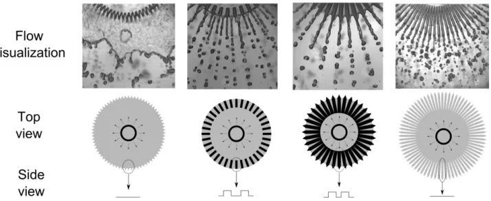
The figure 6 shows the different structures used on the border of the disk in order to generate cylindrical jets. The pictures come from preliminary tests so the flow parameters were not equal between each case therefore no quantitative comparisons were realized so far. The disks were plexiglass cut with a laser cutter. For the first design the disk was cut with teeth at its end. This design was unable to form jet at its exit, the teeth were too short and only a liquid sheet was formed. The second and the third design had grooves on the border of the plate. These grooves were able to correctly guide the flow to coarse jets (~1mm) but when the number of jet increased, the jets were merging was formed. The last design is the most promising way because of its ability to generate a large number of jets without slowing down too much the flow.
Figure 5. Comparison of several plate structures for jet generation. The black areas on the side of the sketch correspond to grooves. The arrows are showing the flow directions on the disk.
Acknowledgements
I would like to thanks the FNRS for the funding of my PhD through the F.R.I.A. PhD grant.
References
Brenn G, Durst F, Tropea C. 1996. Monodisperse Sprays for Various Purposes – Their
Production and Characteristics. Part. Part. Syst. Charact. 13:179–185.
Brenn G, Lackermeier U. 1997. Drop formation from a vibrating orifice generator driven by
De Cock N, Massinon M, Mercatoris B C N, Lebeau F. 2014. Numerical modeling of a mirror nozzle flow. Asabe meeting (2014) Montreal, Canada.
Dumouchel C. 2008. On the experimental investigation on primary atomization of liquid streams.
Experiments in fluids 45(3):371–422.
Ellis M B, Tuck C, Miller P. 1997. The effect of some adjuvants on sprays produced by
agricultural flat fan nozzles. Crop Protection 16(1):41 – 50.
Ellis M B, Tuck C, Miller P. 2001. How surface tension of surfactant solutions influences the
characteristics of sprays produced by hydraulic nozzles used for pesticide application. Colloids and Surfaces A: Physicochemical and Engineering Aspects 180(3):267 – 276.
Holloway P, Ellis M B, Webb D, Western N, Tuck C, Hayes A, Miller P. 2000. Effects of some
agricultural tank-mix adjuvants on the deposition efficiency of aqueous sprays on foliage. Crop Protection 19(1):27 – 37.
Lichtarowicz A, Markland E. 1963. Calculation of potential flow with separation in a right-angled
elbow with unequal branches. Journal of Fluid Mechanics 17:596-606.
Miller P, Ellis M B. 2000. Effects of formulation on spray nozzle performance for applications
from ground-based boom sprayers. Crop Protection 19(8–10):609 – 615.
Massinon M, Lebeau F. 2012. Experimental method for the assessment of agricultural spray
retention based on high-speed imaging of drop impact on a synthetic superhydrophobic surface. Biosystems Engineering 112(1):56 – 64.
Matthews G. 2008. Pesticide application methods. John Wiley & Sons.
Nuyttens D, Baetens K, Schampheleire M D, Sonck B. 2007. Effect of nozzle type, size and
pressure on spray droplet characteristics. Biosystems Engineering 97(3):333 – 345.
Reichenberger S, Bach M, Skitschak A, Frede H-G. 2007. Mitigation strategies to reduce
pesticide inputs into ground- and surface water and their effectiveness; a review. Science of The Total Environment 384(1–3):1 – 35.
Roshko A. 1954. A new hodograph for free-streamline theory
Strutt J W, Lord Rayleigh. 1878. On the instability of jets. Proc. London Math. Soc 10(3):4–13. Taylor P, Womac A, Taylor B. 2004. An attempt to relate drop size to drift risk. International
Conference on Pesticide Application for Drift Management.
Watson E J. 1964. The radial spread of a liquid jet over a horizontal plane, Journal of Fluid
Mechanics 20:481–499. .


