DOCTORAT DE L'UNIVERSITÉ DE TOULOUSE
Délivré par :
Institut National Polytechnique de Toulouse (Toulouse INP)
Discipline ou spécialité :
Chimie Organométallique et de Coordination
Présentée et soutenue par :
M. ROBERTO MORALES CERRADA le jeudi 15 novembre 2018
Titre :
Unité de recherche : Ecole doctorale :
Complexes de manganèse pentacarbonyle alkyle et fluoroalkyle comme
modèles d'espèces dormantes de l'OMRP
Sciences de la Matière (SDM)
Laboratoire de Chimie de Coordination (L.C.C.)
Directeur(s) de Thèse :
MME FLORENCE GAYET M. BRUNO AMEDURI
Rapporteurs :
M. GERARD JAOUEN, UNIVERSITE PARIS 6 Mme SOPHIE GUILLAUME, CNRS
Membre(s) du jury :
M. MATHIAS DESTARAC, UNIVERSITE TOULOUSE 3, Président M. BRUNO AMEDURI, CNRS, Membre
M. HENRI CRAMAIL, INP BORDEAUX, Membre Mme FLORENCE GAYET, INP TOULOUSE, Membre
‐ iii ‐
Ce travail a été réalisé dans deux unités de recherche du CNRS : le laboratoire de Chimie de Coordination (LCC) à Toulouse, au sein de l’équipe LAC2, et l’Institut Charles
Gerhardt de Montpellier (ICGM), au sein de l’équipe IAM. Il a été codirigé par Dr. Florence Gayet et Dr. Bruno Améduri.
Je tiens tout d’abord à remercier Dr. Azzedine Bousseksou, directeur du LCC, et Dr. Patrick Lacroix‐Desmazes, directeur de l’équipe IAM à l’ICGM, pour avoir accepté de m’accueillir au sein de ses laboratoires.
Je remercie tout particulièrement mes directeurs de thèse, Dr. Florence Gayet et Dr. Bruno Améduri, pour m’avoir encadré durant ces trois années de doctorat. Un immense merci à tous les deux pour tous leurs conseils, leur patience et leurs connaissances qui m’ont apporté et qui m’ont permis de mener à bien ce travail.
Je suis très honoré que Dr. Sophie Guillaume et Prof. Gérald Jaouen aient accepté d’être rapporteurs. Qu’ils trouvent ici l’expression de ma profonde reconnaissance et mes sincères remerciements.
J’exprime également ma gratitude au Prof. Mathias Destarac et au Prof. Henri Cramail, qui ont bien voulu être examinateurs.
Un très grand merci également au Prof. Rinaldo Poli pour toute son aide apportée pendant ces trois années de thèse et de son expertise en chimie qui m’a permis de résoudre un grand nombre de questions et problèmes auxquels j’ai dû faire face. Qu’il soit aussi remercié pour sa gentillesse, sa disponibilité permanente et pour les nombreux encouragements qu’il m’a prodigués.
Je remercie Dr. Vincent Ladmiral et Dr. Christophe Fliedel pour leur aide et leurs conseils, Dr. Antoine Debuigne et Dr. Christophe Detrembleur pour leurs conseils lors des réunions d’avancement du projet, ainsi que l’ensemble de personnes qui ont participé à ce travail. Merci au Dr. Jean‐Claude Daran pour son expertise à déterminer la plupart des structures DRX de ce travail. Mme Dominique Granier et Dr. Arie Van der
pour son aide en caractérisation des polymères par chromatographie d’exclusion stérique. Je tiens à remercier l’ensemble du personnel du LCC et de l’ICGM, avec une mention spéciale à Sandrine Vincendeau pour toute son aide pour mettre en place un grand nombre d’expériences, ainsi que de m’avoir accueilli au laboratoire toujours avec un grand sourire, Dr. Eric Manoury pour son aide dans le domaine de la chimie organique et sa bonne humeur, Dr. Agnès Labande pour ses conseils et gentillesse et Dr. Abdellatif Manseri pour son support technique et son humour. Je remercie également l’ensemble des personnes que j’ai côtoyé tout au long de la thèse, notamment Dr. Ekaterina Bellan, Maxime Colpaert, Dr. Gérald Lopez, Marc Guerre, Dr. Qizhi Yang, Mohammad Wehbi, Dr. Panagiotis Falireas, Erinque Folgado et Kazuki Komoda.
Je remercie l’Agence Nationale de la Recherche (ANR) pour avoir financé ces recherches dans le cadre du projet FLUPOL.
Je tiens également à remercier très chaleureusement toute ma famille qui m’a soutenu et motivé pendant ces trois ans.
Enfin, je tiens à remercier ma compagne María José pour sa patience et son soutien tout au long de ce travail.
‐ v ‐
‐ vii ‐ acac Acetylacetonate Acetone‐d6 Deuterated acetone AFCT Addition‐Fragmentation Chain Transfer ATRP Atom Transfer Radical Polymerization b. p. Boiling Point BDE Bond Dissociation Enthalpy Benzene‐d6 Deuterated benzene BrTFE Bromotrifluoroethylene CMRP Cobalt‐Mediated Radical Polymerization CRP Controlled Radical Polymerization CSIRO Commonwealth Scientific and Industrial Research Organization CTA Control Transfer Agent CTFE Chlorotrifluoroethylene D.P. Degree of Polymerization DCM Dichloromethane DFAA Difluoroacetic anhydride DFT Density Functional Theory DMC Dimethyl Carbonate DMF‐d6 Deuterated dimethylformamide DMSO‐d6 Deuterated dimethyl sulfoxide DSC Differential Scanning Calorimetry Ɖ Dispersity FEVE Fluoroethylenevinylether FTIR Fourier‐Transform Infrared spectroscopy HF Hydrogen Fluoride HOAO Highest Occupied Atomic Orbital ITP Iodine Transfer Polymerization ka Activation rate constant kd Deactivation rate constant L Ligand
MAF‐TBE tert-butyl-2-trifluoromethacrylate MMA Methyl Methacrylate Mt Metal NaK Sodium‐potassium metallic liquid alloy NMP Nitroxide‐Mediated Polymerization NMR Nuclear Magnetic Resonance OMRP Organometallic‐Mediated Radical Polymerization
OMRP‐DT Organometallic‐Mediated Radical Polymerization – Degenerative Transfer OMRP‐RT Organometallic‐Mediated Radical Polymerization – Reversible Termination ORD Optical Rotatory Dispersion PMA Poly(Methyl acrylate) PMMA Poly(Methyl Methacrylate) ppm Parts‐Per‐Million (10‐6) PPN+ Bis(triphenylphosphine)iminium PS Poly(Styrene) PTFE Poly(Tetrafluoroethylene) PVAc Poly(Vinyl Acetate) PVDF or PVF2 Poly(Vinylidene Fluoride) PVDFH PVDF‐(CF2CH2)‐ PVDFT PVDF‐(CH2CF2)‐ PVF Poly(Vinyl Fluoride) R Alkyl chain RAFT Reversible Addition‐Fragmentation chain Transfer RDRP Reversible‐Deactivation Radical Polymerization RF Fluoroalkyl chain S Styrene SEC Size exclusion chromatography TFAA Trifluoroacetic anhydride TFE Tetrafluoroethylene TFP 3,3,3‐Trifluoropropene TGA Thermogravimetric Analysis
‐ ix ‐
TrFE Trifluoroethylene
UV Ultraviolet
VDF or VF2 Vinylidene Fluoride
‐ xi ‐ General introduction ... 1 1. State‐of‐the‐art ... 7 1.1. Fluorinated polymers ... 9 1.1.1. Introduction ... 9 1.1.2. Vinylidene fluoride and poly(vinylidene fluoride) ... 10 1.1.3. Polymerization of fluoromonomers ... 12 1.1.4. Coordination‐insertion polymerization ... 16 1.1.5. Controlled radical polymerization of fluoromonomers ... 17 1.2. Metal carbonyl complexes ... 25 1.2.1. Structure and bonding ... 26 1.2.2. Physical characteristics ... 27 1.2.3. Applications ... 28 1.2.4. Techniques of characterization ... 28 1.2.5. Manganese carbonyl complexes ... 29 1.2.6. Dimanganese decarbonyl ... 29 1.2.7. Manganese carbonyl derivates ... 32 1.3. Conclusion ... 37 1.4. References ... 39 2. Alkylpentacarbonylmanganese(I) complexes ... 45 2.1. Introduction ... 47 2.2. Results and discussion ... 49 2.2.1. Synthesis of potassium pentacarbonylmanganate ... 49 2.2.2. 1‐Methyl‐2‐methoxy‐2‐oxoethylpentacarbonylmanganese(I), 1 ... 51 2.2.3. 1‐Acetyloxyethylpentacarbonylmanganese(I), 2 ... 56 2.2.4. 1‐Phenylethylpentacarbonylmanganese(I), 3 ... 63 2.3. Conclusion ... 68 2.4. Experimental section ... 70 2.5. References ... 73
3.2. Results and discussion ... 79 3.2.1. Trifluoromethylpentacarbonylmanganese(I), 8 ... 79 3.2.2. Difluoromethylpentacarbonylmanganese(I), 9 ... 88 3.2.3. 2,2,2‐Trifluoroethylpentacarbonylmanganese(I), 10 ... 96 3.2.4. 1,1‐Difluoroethylpentacarbonylmanganese(I), 11 ... 104 3.2.5. Vibrational analysis of the fluoroalkylpentacarbonylmanganese(I) derivates ... 113 3.2.6. Comparative analysis of the X‐ray structures ... 118 3.3. Conclusion ... 120 3.4. Experimental section ... 121 3.5. References ... 127 4. Manganese‐carbon bond dissociation enthalpy studies of [Mn(CO)5R] complexes ... 129 4.1. Introduction ... 131 4.2. Results and discussion ... 134 4.2.1. Experimental determination of the Mn‐CF3 BDE in 8 ... 137 4.2.2. Experimental determination of the Mn‐CHF2 BDE in 9 ... 141 4.2.3. Experimental determination of the Mn‐CH2CF3 BDE in 10 ... 143
4.2.4. Experimental determination of the Mn‐CH(CH3)(COOCH3) BDE in 1 .... 144
4.2.5. Discussion of the Mn‐C homolytic bond strength in the alkyl and fluoroalkylpentacarbonylmanganese(I) derivatives ... 147 4.2.6. Analysis of side‐reactions in the decomposition of [Mn(CO)5RF] complexes ... 148 4.2.7. DFT investigation of the homolytic cleavage and the side reaction pathway ... 155 4.3. Conclusion ... 166 4.4. Experimental section ... 167 4.5. References ... 168
‐ xiii ‐ ... 171 5.1. Introduction ... 173 5.2. Results and discussion ... 176 5.2.1. Polymerizations of VDF with [Mn(CO)5RF] ... 176 5.2.2. VDF/[Mn(CO)5(CF3)] ... 177 5.2.3. VDF/[Mn(CO)5(CHF2)] ... 194 5.2.4. VDF/[Mn(CO)5(CH2CF3)] ... 196 5.2.5. VDF/[Mn(CO)5(COCF2CH3)] ... 198 5.2.6. Thermal properties of PVDF synthesized by different activations methods ... 204 5.3. VAc/MAF‐TBE copolymerization with [Mn(CO)5RF] ... 207 5.4. Polymerization of methyl acrylate with [Mn(CO)5(CH(CH3)(COOCH3))] ... 209 5.5. Polymerization of styrene with [Mn(CO)5(CH(CH3)(C6H5))] ... 213 5.6. Conclusion ... 217 5.7. Experimental section ... 218 5.8. References ... 221 General conclusion ... 225 Appendix ... 231
‐ 1 ‐
‐ 3 ‐
General introduction
Controlled radical polymerization (CRP and also called reversible‐deactivation radical polymerization or RDRP) makes possible to synthesize innovative architectures inaccessible by any other method. The first controlled radical polymerization, the iodine transfer polymerization (ITP), was described for the very first time by researchers at Daikin Company (Japan) in 1979,[1] but it was not until the mid‐1990s that RDRP methods
were exceptionally well‐developed.
Macromolecular engineering concerns well‐defined architectures such as block copolymers, grafted, star‐shaped, hyperbranched or dendrimers. Among the various RDRP techniques, the most common are nitroxide mediated polymerization (NMP),[2‐5]
atom transfer radical polymerization (ATRP),[6‐8] reversible addition‐fragmentation
chain‐transfer polymerization (RAFT),[9‐11] ITP,[12] organometallic mediated radical
polymerization (OMRP)[13] or telluride‐mediated polymerizartion (TERP).[14] ITP is the
oldest RDRP method that has led to the first industrial developments (fluorinated thermoplastic elastomers).[15] It is applicable to fluorinated olefins such as
tetrafluoroethylene (TFE), vinylidene fluoride (VDF) and TFE/VDF copolymers, VDF/HFP (HFP: hexafluoropropene), VDF/CTFE (CTFE: chlorotrifluoroethylene), etc.[11,16]
Fluoropolymers are macromolecules which possess remarkable properties (hydrophobicity, oleophobicity, thermostability, low refractive index, low dielectric constant, etc.)[17] finding applications in high‐tech fields (thermostable, high
performance elastomers, gaskets and O‐rings for aerospace sealing, sheaths and cores of optical fibers, wires, paints, coatings, etc.).[17] These polymers are generally
synthesized by radical (co)polymerization and industrially manufactured by large American companies (EI du Pont of Nemours and Company, Chemours, 3M, Dyneon, Gore, Honeywell, Halocarbon), Japanese (Daikin, Asahi Glass Chemical, Mitsue, Showa Denko, Kureha), Chinese (F & F, Juhua, Dongyue) and European (Arkema, Solvay Specific Polymers ), etc.
Historically, the first fluoropolymer was discovered in 1934 by IG Farbenindustrie AG[18], then Plunkett[19] (at E. I. du Pont de Nemours and Co.) accidentally obtained PTFE
but it was not until the late 1970s that it carried out the first work on the RDRP of fluorinated monomers.[1] Although many studies on the RDRP of styrenic and
(meth)acrylic monomers are reported in the literature, the RDRP of fluorinated olefins remains a real scientific challenge.[20] Only ITP[16,21‐23] and RAFT polymerization have
proven effective, for instance RAFT homopolymerization of VDF[24‐26] or
copolymerization of VDF with 3,3,3‐trifluoropropene,[27] with
perfluoromethylvinylether[28] or with tert‐butyl 2‐trifluoromethylacrylate.[29] Both techniques have led to block copolymers,[30] nevertheless they suffer a loss of control because the CF2CH2X (with X = I or SC(S)OEt) chain‐ends are generated by the inverse (head‐to‐head) addition of the monomer, which are more difficult to reactivate under thermal conditions, leading to an accumulation of PVDF having such terminations. However, these disadvantages could be overpassed by the presence of decacarbonyl dimanganese, [Mn2(CO)10], under the effect of a visible irradiation.[31,32] This strategy of
ITP allowed to improve the control of the polymerization of VDF obtaining long polymer chains and to synthesize block copolymers. More recently, the polymerization of VDF has been effectively controlled by cobalt complexes (CMRP) leading to original PVDF‐b‐PVAc block copolymers and PVDF‐b‐PVAc‐b‐PVDF triblocks. We therefore found it interesting to continue this study of the OMRP and to synthesize organometallic complexes based on manganese. The aim of this thesis is therefore the study of the use of [Mn(CO)5R] organometallic complexes of the in the polymerization of fluorinated and nonfluorinated monomers. This thesis is composed of five parts: a first chapter will focus on a non‐exhaustive state‐ of‐the‐art on fluorinated polymers and organometallic complexes based on manganese. The second and third chapters will describe the synthesis, structure and spectroscopic characterization of [Mn(CO)5R] complexes, with R = alkyl and fluoroalkyl chain
respectively. In a third chapter, we will study theoretically and experimentally the dissociation enthalpy of the Mn‐C bond for some of these complexes. A final part will concern the study of the radical polymerization initiated by the complexes synthesized
‐ 5 ‐ in this work. The polymers obtained will be characterized to check if there is any control on the polymerization, before ending with the general conclusion.
References
[1] M. Tatemoto In First Regular Meeting of Soviet‐Japanese Fluorine Chemists Tokyo, 1979. [2] C. J. Hawker; A. W. Bosman; E. Harth Chem. Rev. 2001, 101, 3661‐3688. [3] V. Sciannamea; R. Jérôme; C. Detrembleur Chem. Rev. 2008, 108, 1104‐1126. [4] D. Gigmes Nitroxide Mediated Polymerization: From Fundamentals to Applications in Materials Science. [In: RSC Polym. Chem. Ser., 2016; 19]; RSC, 2016. [5] J. Nicolas; Y. Guillaneuf; C. Lefay; D. Bertin; D. Gigmes; B. Charleux Prog. Polym. Sci. 2013, 38, 63‐235. [6] K. Matyjaszewski; J. Xia Chem. Rev. 2001, 101, 2921‐2990. [7] W. A. Braunecker; K. Matyjaszewski Prog. Polym. Sci. 2007, 32, 93‐146. [8] M. Kamigaito; T. Ando; M. Sawamoto Chem. Rev. 2001, 101, 3689‐3745. [9] S. Perrier Macromolecules 2017, 50, 7433‐7447. [10] C. Barner‐Kowollik Handbook of RAFT Polymerization; Wiley‐VCH Verlag GmbH & Co. KGaA, 2008. [11] M. R. Hill; R. N. Carmean; B. S. Sumerlin Macromolecules 2015, 48, 5459‐5469. [12] G. David; C. Boyer; J. Tonnar; B. Ameduri; P. Lacroix‐Desmazes; B. Boutevin Chem. Rev. 2006, 106, 3936‐3962. [13] A. Debuigne; R. Poli; C. Jerome; R. Jerome; C. Detrembleur Prog. Polym. Sci. 2009, 34, 211‐239. [14] S. Yamago Chem. Rev. 2009, 109, 5051‐5068.[15] M. Tatemoto (Daikin Industries). Fluorine‐containing elastomer composition. EP 0399543 A2, 1990. [16] M. Oka; M. Tatemoto In Contemporary Topics in Polymer Science: Volume 4; Bailey, W. J., Tsuruta, T., Eds.; Springer: Boston, 1984, p 763‐777. [17] B. Ameduri; H. Sawada Fluorinated polymers; Royal Society of Chemistry, 2017; Vol. 1&2. [18] IG Farbenindustrie AG. GB 465520, 1937. [19] R. J. Plunkett (Kinetic Chemicals, Inc.). Tetrafluoroethylene polymers. US 2230654, 1941. [20] B. Ameduri Macromolecules 2010, 43, 10163‐10184.
[21] C. Boyer; D. Valade; L. Sauguet; B. Ameduri; B. Boutevin Macromolecules 2005, 38,
10353‐10362. [22] C. Boyer; D. Valade; P. Lacroix‐Desmazes; B. Ameduri; B. Boutevin J. Polym. Sci., Part A: Polym. Chem. 2006, 44, 5763‐5777. [23] C. Boyer; B. Ameduri; M. H. Hung Macromolecules 2010, 43, 3652‐3663. [24] M. Guerre; B. Campagne; O. Gimello; K. Parra; B. Ameduri; V. Ladmiral Macromolecules 2015, 48, 7810‐7822. [25] M. Guerre; S. M. W. Rahaman; B. Ameduri; R. Poli; V. Ladmiral Macromolecules 2016, 49, 5386‐5396. [26] M. Guerre; M. Semsarilar; F. Godiard; B. Ameduri; V. Ladmiral Polym. Chem. 2017, 8, 1477‐1487.
[27] G. Kostov; F. Boschet; J. Buller; L. Badache; S. Brandsadter; B. Ameduri Macromolecules 2011, 44, 1841‐1855. [28] E. Girard; J.‐D. Marty; B. Ameduri; M. Destarac ACS Macro Letters 2012, 1, 270‐274. [29] Y. Patil; B. Ameduri Polym. Chem. 2013, 4, 2783‐2799. [30] M. Guerre; J. Schmidt; Y. Talmon; B. Ameduri; V. Ladmiral Polym. Chem. 2017, 8, 1125‐ 1128. [31] A. D. Asandei; O. I. Adebolu; C. P. Simpson J. Am. Chem. Soc. 2012, 134, 6080‐6083. [32] A. D. Asandei Chem. Rev. 2016, 116, 2244‐2274.
‐ 7 ‐
Chapter 1
State‐of‐the‐art
Outline:
1.1. Fluorinated polymers ... 9
1.1.1. Introduction ... 9
1.1.2. Vinylidene fluoride and poly(vinylidene fluoride) ... 10
1.1.3. Polymerization of fluoromonomers ... 12
1.1.4. Coordination‐insertion polymerization ... 16
1.1.5. Controlled radical polymerization of fluoromonomers ... 17
1.2. Metal carbonyl complexes ... 25
1.2.1. Structure and bonding ... 26
1.2.2. Physical characteristics ... 27
1.2.3. Applications ... 28
1.2.4. Techniques of characterization ... 28
1.2.5. Manganese carbonyl complexes ... 29
1.2.6. Dimanganese decarbonyl ... 29
1.2.7. Manganese carbonyl derivates ... 32
1.3. Conclusion ... 37
1.4. References ... 39
‐ 9 ‐
1.
State‐of‐the‐art
1.1. Fluorinated polymers
1.1.1.
Introduction
Fluorine and fluorinated compounds are very present in our daily lives. Fluorine is unique because it is possible to substitute hydrogen by fluorine in organic compounds without a great distortion of the geometry of the system but, surprisingly, compounds containing carbon‐fluorine bonds are rare in nature.[1,2] However, many syntheticproducts contain fluorine such as fluoridated water, fluorinated drugs (e.g. Ciprofloxacin®, Prozac®), anesthetics, agrochemical products, refrigerants, fluoride toothpaste, as well as fluoride additives in lithium batteries.[3‐6] Even though the use of
fluorine in organic and inorganic chemistry dates from the 17th century,[7] the great
development of fluorine chemistry has occurred in the early‐to‐mid 20th century (e.g.
synthesis of trifluoroacetic acid in 1920 by Swartz, isolation of carbon tetrafluoride by Lebeau and Damien in 1926).[8,9]
Fluorine chemistry has an important impact in materials chemistry, especially with the fluorinated polymers and copolymers.[5,10‐14] They are niche and specialty polymers
with a high production cost and a low production scale (around 4.5% of the World polymer production) contrary to commodity polymers, which are unexpensive and synthesized on a large scale. These materials have attracted wide attention in both industry and academia due to the low polarizability and the very strong electronegativity of fluorine. This induces a short (1.32 Å) and strong (485 kJ∙mol‐1) C‐F bond. The
morphologies of fluoropolymers can be either thermoplastic, elastomeric,[15]
plastomeric, or even thermoplastic elastomeric, and they can be either semicrystalline or totally amorphous. All these specific characteristics confer outstanding properties to the fluorinated polymers,[16] such as high thermal, chemical, aging and weather
resistance, excellent inertness to solvents, to hydrocarbons, to acids, and to alkalis, low surface energy (oil and water repellency), low dielectric constants, low flammability, low refractive index, and low moisture absorption. Moreover, the presence of the strong C‐ F bond has a decisive impact on the high resistance to oxidation and other kinds of degradation. The aforementioned extraordinary properties make fluoropolymers advantageous materials, involved in many products such as paints and coatings (Figure 1), optical fibers, fuel cell membranes, gaskets and O‐rings for use in extreme temperatures, textile and microelectronics among others. They are also used in many industrial sectors such as petrochemical, automotive, aeronautics, aerospace, building treatments, etc. However, fluoropolymers have several drawbacks such as their low solubility in the most common organic solvents due to their high crystallinity. Nevertheless, this property can be an advantage in terms of chemical resistance. In addition, fluorinated copolymers[12,13,17] possess a higher solubility in organic solvents, because the presence of a comomoner (bearing side groups) creates a certain disorder in the structure that reduces the degree of crystallinity. Figure 1. Left picture: fluoroethylenevinylether (FEVE)‐based paints are used to coat exposed constructions such as the Akashi‐Kaikyo Bridge in Japan, one of the world’s longest suspension bridges.[18] Right picture: solar panels are coated with fluoropolymers such as polyvinylfluoride (PVF) to impart photoresistance and weather durability.[18]
‐ 11 ‐
1.1.2.
Vinylidene fluoride and poly(vinylidene fluoride)
1,1‐Difluoroethylene, also called vinylidene fluoride (VDF or VF2), is a
hydrofluoroolefin with the chemical formula F2C=CH2. The CF2 extremity is usually
named the “head” and the CH2 the “tail”. It is a colorless, flammable, and nearly odorless
gas that boils at ‐82 °C and it melts at ‐144 °C. VDF exhibits several advantages: it is a non‐toxic fluorinated gas in contrast to chlorotrifluoroethylene (CTFE) and bromotrifluoroethylene (BrTFE), non‐explosive contrarily to tetrafluoroethylene (TFE) or trifluoroethylene (TrFE), and can easily homopolymerize and copolymerize by radical initiation.[17,19]
VDF can be prepared by various methods. The principal industrial process consists of the chlorination of 1,1‐difluoroethane to lead to 1‐chloro‐1,1‐difluoroethane, followed by a dehydrochlorination at about 700‐900 °C.[17]
The resulting polymer, the poly(vinylidene fluoride), also called PVDF or PVF2, is a
specialty thermoplastic belonging to the fluoropolymer family. After polytetrafluoroethylene (PTFE), it is the second most produced and consumed fluoropolymer in the world market (Figure 2).
PVDF is a thermoplastic and non‐reactive fluoropolymer (except against strong bases, producing HF). It is primarily involved in applications that require high resistance to solvents, acids and heat. It is also employed as an important component in high‐end paints for metal roofing in commercial and residential applications, as well as for separators and binders in lithium‐ion batteries.[21] Membranes of PVDF are extensively
consumed for the purpose of immobilizing proteins, as well as for water purification[22]
and ferro‐ and piezoelectrical devices.[23] PVDF is also used widely in sheets, films,
membranes and coatings in various end‐user industries such as chemical processing, oil and gas, construction and energy.[21] The high demand from different industries such as
coatings, photovoltaic films, oil and gas, and electrical appliances are expected to grow the PVDF market.[24,25] Arkema, Daikin Industries Ltd., Dyneon GmbH, Shanghai
Ofluorine Chemical Technology Co. Ltd., Shanghai 3F New Materials Co. Ltd., Solvay S.A., Zhuzhou Hongda Polymer Materials Co. Ltd., Zhejiang Fotech International Co. Ltd., Kureha Corporation and Quadrant Engineering Plastics Products Inc. are some of the main manufacturers of PVDF dominating the market.
1.1.3.
Polymerization of fluoromonomers
1.1.3.1. Conventional radical polymerization
Conventional radical polymerization is the oldest method to synthesize polymers and this technique is well suited to fluoroolefins. The process takes place in three main steps. The first one is the initiation where a radical is generated from a stable molecule called initiator (which can be activated by a stimulus such as thermal, UV or visible irradiation, ionization, electrolysis, etc.). Then, during the propagation, the radical reacts with a monomer generating a C‐C bond and transferring to it the radical function, which then reacts again with another monomer and so on. Finally, the last step is the termination by recombination (with another macroradical or with an initiator radical) or by the reaction of the active radical chain with an inhibitor such as oxygen or any molecule that reacts with a radical. Another possibility to deactivate the growing chain‐ 13 ‐
is the hydrogen transfer from the solvent or other molecule able to transfer a proton, killing the active chain (Scheme 1).
Scheme 1. Example of the general mechanism of the free radical polymerization.
Conventional radical polymerization is the most employed method to obtain fluorinated polymers (95% of the World production).[16] Most of fluoropolymers are
synthesized by this method,[10,12,13,26] notwithstanding a few fluorinated monomers are
polymerized by anionic (hexafluoropropylene oxide) or cationic (oxetanes, oxazoline or vinyl ethers; H2C=CHORF) mechanisms. In fact, certain fluorinated monomers such as
hexafluoropropylene or perfluoroalkyl vinyl ethers cannot homopolymerize by conventional radical polymerization.
1.1.3.2. Cationic polymerization
Cationic polymerization is a polymerization in which a cationic initiator adds to a monomer which is then transformed into a reactive carbocation and then reacts with other monomers to form the polymer.[27] This polymerization is limited to monomers such as olefins with electron‐donating substituents and heterocycles.The first step is the initiation, where a carbenium ion is generated with a non‐ nucleophilic (or weakly nucleophilic) counterion to avoid the recombination. This carbenium ion can be generated by a strong acid (Lewis or Brønsted), by a stable
carbenium ion salts or by an ionizing radiation.[28] Then, the propagation consists in the
addition of the monomer to the carbenium ion, linking the monomer to the chain via a carbon‐carbon bond and regenerating the carbenium ion at the end of the chain. Finally, termination occurs when the counterion reacts with the carbenium ion via a unimolecular rearrangement or when other nucleophilic reagents irreversibly add to quench the cationic reaction center (Scheme 2). Scheme 2. Example of the general mechanism of cationic polymerization.
Moreover, cationic polymerization can be a living polymerization to control the growth and obtain well‐defined polymers.[29] For this, the termination step should be
reduced or eliminated, stopping the reaction when all the monomer is consumed. Only a few fluorinated monomers can polymerize by this way. For instance, the fluorinated monomers that have been used in cationic polymerization are fluorinated oxetanes,[30‐32] oxazolines,[33‐35] and vinyl ethers bearing a fluorinated group (Scheme
3).[36‐39] Scheme 3. Chemical structure of oxetane, oxazoline and vinyl ether.
‐ 15 ‐
1.1.3.3. Anionic polymerization
The anionic polymerization[40] of vinyl monomers involves a carbanionic species. To stabilize the negative charge of the carbanion, the vinyl monomer should bear a high electronegative group or stabilize the charge by mesomeric effects. For instance, monomers like styrene, diene, methacrylate and vinyl pyridine among others can react by this way.The initiation occurs by the generation of a carbanion in the monomer. This can be produced by an electron transfer from an alkali metal or by strong anions such as alkyllithium compounds. Propagation in anionic radical polymerization is a very fast process and occurs until total consumption of the monomer, even at low temperatures. Then, termination only takes place by quenching due to impurity traces or by intentional addition of quenching agents such as water, alcohols, oxygen or carbon dioxide (Scheme 4). Scheme 4. Example of the general mechanism of anionic polymerization. In the absence of impurities, the carbanion would still be active and capable of adding another monomer, giving place to a living radical polymerization. The chains will remain active indefinitely unless there is a termination or a chain transfer. Like the cationic polymerization, only a few fluorinated monomers can react by anionic polymerization such as α‐trifluoromethacrylic acid.[41,42]
1.1.4.
Coordination‐insertion polymerization of
fluoromonomers
Coordination‐insertion polymerization (or coordination polymerization) is a kind of polymerization catalyzed by complexes or transitions metal salts. Ziegler[43,44] and
Natta[45,46] were pioneered in the mid‐1950s in this technique with the use of
heterogeneous catalyst based on an organoaluminium and titanium or vanadium tetrachloride to polymerize ethylene and propylene. These studies led them to win the Nobel Prize in Chemistry in 1963.[47] Other homogeneous catalysts were developed at
the end of 1950s by Breslow et al.,[48] based on titanium metallocenes and aluminum
complexes, however the polymerization mechanism was not well‐known at this time. At the beginning of 1970s, Meyer et al.[49] carried out kinetic studies on alkylaluminum
activated metallocene catalysts, revealing that polymer growth alternated between dormant and active states.
In the last 40 years, there has been a great development in the use of homogeneous catalysts for polymerization via insertion‐coordination, especially to make polyethylene and polypropylene. Additionally, this polymerization method allow synthesizing copolymers with polar and non‐polar functions such as polar vinyl monomers and non‐ polar olefins.[50] Concerning the fluoromonomers, some recent studies about the copolymerization of ethylene and vinyl fluoride (VF) have been reported by Jordan et al.[51] using palladium phospine‐sulfonate complexes. The obtained copolymers have molar masses of 4500‐ 14500 g∙mol‐1 and a high content in ethylene and thus low content in VF (< 0.5 mol %). This was produced by the weak ability of VF to coordinate to the palladium(II) catalyst compare to ethylene. More recent studies of this research group reported with a similar system the way to increase the proportion of VF in the polymer,[52] and the introduction of fluorine atoms in this copolymer by a β‐F elimination.[53]
‐ 17 ‐
1.1.5.
Controlled radical polymerization of
fluoromonomers
The history of controlled radical copolymerization (CRP) or reversible‐deactivation radical polymerization (RDRP) started in the late 1970s when Tatemoto pioneered the concept on the iodine transfer (co)polymerization (ITP) of fluoroalkenes, especially on vinylidene fluoride.[54]Since then, and especially in the 1990s, RDRP methods have undergone an extraordinary development by the improvement of the known methods or the discovery of new ones.[55] All these methods are based on the formation of a dormant species (or
capped chains), which cannot react with another monomer, in a fast equilibrium with active chains (Scheme 5). This reaction should be fast, reversible and with a large majority of dormant species. The dormant chains may be alkyl halides (typically chlorides or bromides for atom transfer radical polymerization or ATRP[56,57] or iodide
for ITP),[58] thioesters (reversible addition‐fragmentation chain transfer polymerization
or RAFT polymerization),[59‐61] alkoxyamines (nitroxide‐mediated polymerization or
NMP),[62,63] or an organometallic species (organometallic‐mediated radical
polymerization or OMRP).[64,65] Free radicals may be generated by the spontaneous
thermal process (NMP), via a catalyzed reaction (ATRP) or reversibly via the degenerative exchange process with dormant species (RAFT and ITP).
1.1.5.1. ITP
As mentioned above, ITP was the first RDRP technique used in the late 1970s by Tatemoto[54,66,67] to control the (co)polymerization of fluoroolefins, even before the
findings of CRP or RDRP in the mid‐1990s. Various fluorinated monomers such as VDF and TFE have been successfully used in ITP within Daikin Industries. From that advance, this company has been producing by ITP many fluorinated thermoplastic elastomers (based on thermoplastic‐b‐elastomers‐b‐thermoplastic block copolymers) for more than 20 years.[13,67,68] Other companies such as Ausimont S.p.A.[69] and E.I. du Pont de
Nemours and Co[70] have been inspired from this RDRP method to produce other
fluorinated block copolymers.
The general mechanism of ITP consists of six main steps as shown in Scheme 6. The first one deals with initiation (1) where the initiator is activated. The second step is the
propagation (2) where the activated initiator reacts with a monomer which can
propagate. Then, the control transfer agent (CTA) transfers an iodine atom onto the growing chain (3), generating a dormant chain and a new radical which is able to react with a monomer (4). Then, iodine is exchanged between the different polymer chains by an iodine degenerative transfer (IDT, step 5). Finally, the termination (6) occurs when two active chains react together or by a hydrogen transfer. Scheme 6. General mechanism of Iodine Transfer Polymerization (ITP).
‐ 19 ‐
Nevertheless, the evidence of the controlled radical polymerization behavior was reported in 2005 by Boyer et al.,[71] through the polymerization of VDF with C6F13I.
Conversely, the same polymerization using HC2F4CH2I gave much worse results and led to telomerization (a radical polymerization where a chain‐transfer reaction restricts the size of the obtained oligomer, usually called telomer, see Scheme 7). A more in‐depth mechanistic approach was reported in a later work,[72] concluding that the presence of ‐CF2‐CH2‐I end‐group is the primary cause of the poor results in the case of HC2F4CH2I. These chains cannot be reactivated and their accumulation led to high dispersities. Scheme 7. General scheme of telomerization process. Nonetheless, this problem can be solved by the reactivation of the reverse dormant chains with the [(CO)5Mn•] radical generated from the dimanganese decacarbonyl under visible light irradiation at 40 °C.[73,74] Dimanganese decacarbonyl is known to generate [(CO)5Mn•] under both thermal and photochemical conditions, but the free [(CO)5Mn•] radicals are not capable to add onto VDF to initiate the polymerization. These results confirm previous studies by Bamford et al.[75] and by Asandei et al.,[73] where [(CO)5Mn•]
photoproduced from [Mn2(CO)10] was shown unable to initiate the radical polymeri‐
zation of VDF (although it can initiate those of C2F4 and C2F3Cl). However, [(CO)5Mn•] can
abstract an iodine atom from the dormant chain‐ends, including from the more recalcitrant PVDFT‐I (PVDF‐CH2‐CF2‐I), to form [Mn(CO)5I] irreversibly and to regenerate
the reactive radical chain. Recently, a similar procedure was employed by Golzari et al.[76] activating the dimanganese decacarbonyl by UV irradiation, and finally obtaining VDF/methyl methacrylate (MMA) or VDF/styrene (S) block copolymers. However the possible direct radical chain trapping to yield PVDF‐Mn(CO)5 was not reported, which would correspond to the dormant species of a putative OMRP process. Despite the possibility to reactivate the PVDFT‐I dormant chain by the manganese pentacarbonyl radical, the polymerization is not so well‐controlled because the iodine
atom is removed irreversibly, decreasing the amount of controlling agent in the system. Other polymerization methods may be the solution to produce a well‐defined PVDF.
1.1.5.2. RAFT/MADIX
The first radical addition‐fragmentation processes were reported in the early 1970s.[77] Nevertheless, the process initially involved non‐degenerate and therefore
irreversible radical exchanges, so the transfer reagents could not be used to control radical polymerization at that time. RAFT polymerization was discovered in 1986 by researchers at the Commonwealth Scientific and Industrial Research Organization (CSIRO). They reported the use of poly(methyl methacrylate) (PMMA) macromonomers as chain transfer agents in radical polymerization and described how a propagating radical would add onto a PMMA macromonomer by a chain‐transfer reaction.[78,79] This
mechanism was initially called addition‐fragmentation chain transfer (AFCT). Several other AFCT agents[78,80,81] were later synthesized, however the polymers obtained by this
method showed high dispersities, until the use of thiocarbonyl‐thio groups by the CSIRO scientists to obtain narrow dispersities for a variety of monomers (Ɖ = 1.05 to 1.40),[82]
concluding that thiocarbonyl‐thio groups are the most efficient chain transfer agents. This system was then renamed “reversible addition‐fragmentation chain transfer” (RAFT).
RAFT and MADIX (macromolecular design by interchange of xanthates) follow the same mechanism and differ only by the polymerization mediator used. This mechanism is based on six main steps as shown in Scheme 8. The first one consists in the activation of the initiator during the initiation (1). The second step is the propagation (2), where a
free‐radical source reacts with a single monomer to yield a propagating polymeric radical Pn•. Then, the propagating radical adds to the thiocarbonyl‐thio compound to
form the radical intermediate, which subsequently fragments to give another thiocarbonyl‐thio group and a new radical R•. This equilibrium is usually called the RAFT
pre‐equilibrium (3). The next step is the re‐initiation (4) and consists in the reaction of
‐ 21 ‐
consumption of the initially added CTA (completion of step 3), the main RAFT
equilibrium (5) is established by degenerative chain transfer between propagating and
dormant chains. Finally, termination (6) may occur by the reaction of two active chains
or by other reactions with the active chain (proton transfer, etc.). A key parameter is the right choice of the Z and R group of the CTA. The Z group primarily affects the stability of the S=C bond and the stability of the adduct radical, while the R group must be able to stabilize the radical (R•) of step 3, but it must be unstable enough to initiate the
growth of a new polymer chain.
Scheme 8. General mechanism of the RAFT/MADIX polymerization.
The RAFT polymerization was used with fluorinated monomers successfully in 2011 by Kostov et al.[83] to carry out the copolymerization of VDF and 3,3,3‐trifluoropropene
(TFP) using xanthates as CTAs (RAFT/MADIX polymerization). Subsequently, the RAFT/MADIX copolymerizations of other fluorinated monomers were reported, such as chlorotrifluoroethylene/tert‐butyl vinyl ether,[84] VDF/perfluoro(methyl vinyl ether),[85]
hexafluoropropene/butyl vinyl ether,[86] VDF/tert‐butyl 2‐trifluoromethacrylate,[87]
The controlled radical homopolymerization of VDF by RAFT/MADIX was more carefully studied by Guerre et al.,[89,90] showing that some degree of control can be
obtained using O‐ethyl‐S‐(1‐methoxycarbonyl)ethyldithiocarbonate as CTA. The loss of control is essentially due to the accumulation of the reverse dormant chains, ‐CF2‐CH2‐Xanthate, which are reactivated much slower than the normal chain ends,
‐CH2‐CF2‐Xanthate,[90,91] and a trick to reactivate them such as the use of [Mn2(CO)10] in
ITP has not yet been found. In addition, a loss of CTA was discovered,[89] which is caused
by irreversible transfer from the dimethyl carbonate (as the solvent).[89] However,
despite the reverse additions and the side reactions, PVDF with 90% chain‐end functionality, with a degree of polymerization (D.P.) of 250 and a dispersity (Ɖ) of 1.49 was obtained, further leading to block copolymers.[89‐92] A cyclic xanthate was also able
to control the RAFT polymerization of VDF further leading to block copolymers, as above.[92] In conclusion, chain defects provoked by reverse additions are intrinsic to radical polymerization and RAFT/MADIX polymerization could not solve the consequences of this phenomenon.
1.1.5.3. Boron‐initiated and regulated CRP
Another possible and more recent method to (co)polymerize fluoroolefins involves alkylboron compounds activated by oxygen. First employed by Natta et al.[93] in 1965, and then revisited and more deeply investigated by Chung’s group,[94‐96] alkylboranes turn out to be efficient initiators and controlling agents for radical polymerization. The mechanism is based on the reaction of the alkylborane BR3 with oxygen to generate RO‐OBR2 in which the O‐O bond undergoes a homolytic cleavage to produce RO• and •OBR2
radicals. RO• can initiate the homopolymerization of VDF (or the copolymerization of
VDF with various other comonomers). In contrast, the •OBR2 radical is too stabilized
and, consequently, is not able to initiate any polymerization. However, it is an effective counter radical which can trap the macroradical by recombination and thus controls the polymerization through a fast equilibrium between the active chain and the dormant
‐ 23 ‐
ones. This method was developed for piezoelectric polymers[96] after the selective
reduction of chlorine atoms of CTFE units in poly(VDF‐co‐CTFE) copolymers to yield poly(VDF‐ter‐CTFE‐ter‐TrFE) or poly‐(VDF‐co‐TrFE) copolymers.
1.1.5.4. Organometallic‐mediated radical polymerization OMRP
Organometallic‐mediated radical polymerization (OMRP) is a more recent technique of controlled radical polymerization (or RDRP) method based on the formation of an organometallic dormant species. The equilibrium between the free radicals of growing chains and the organometallic dormant species must be fast and reversible. Two mechanisms are possible: dissociative (reversible termination, OMRP‐ RT, Scheme 9) where the transition metal of a complex plays the role of a spin‐trap with the generation of the reduced complex, or associative (degenerative transfer, OMRP‐ DT, Scheme 10). The two modes of action may also interplay. Scheme 9. General mechanism of the reversible termination in an OMRP process. . Scheme 10. General mechanism of the degenerative transfer in an OMRP process.
Several suitable reduced [Mtx/L] complexes and/or organometallic initiators
[Mtx+1/L]‐R0 that are capable to regulate the controlled propagation of a variety of
monomers have been designed, synthesized and tested.[64,97‐100] A key is the appropriate
tuning of the Mt‐Rn homolytic bond strength while avoiding harmful side reactivity. The
reactive fluorinated radicals lead to strong bonds with transition metals, thus the generation of metal complexes with suitably weak Mt‐RF bonds is necessary.
The first OMRP process was reported in 1992 by Wayland et al.[101] using rhodium(II)
porphyrins. Two molecules of tetramesitylporphyrinatorhodium(II) reacted with an excess of acrylate monomer to form a dirhodium species bridged by an alkyl chain. Exposure of this complex to visible light cleaved homolytically one of the rhodium‐ acrylate bonds, resulting in the formation of two rhodium species, one with the alkyl chain and the other one without. The one possessing the alkyl chain could initiate the polymerization of acrylic acid, methyl acrylate and ethyl acrylate successfully. Then the growing radical chain was reversibly trapped by rhodium radical without the alkyl chain, with the exchange between dormant and active species leading to some control of the polymerization. Nevertheless, the trapping species could also reinitiate polymerization, through the formation of the bridged dirhodium initiator, resulting in the generation of new growing chains. This uncontrolled initiation, coupled with self‐termination reactions between the growing chains, resulted in broadened dispersities (1.75–2.76) and high molar masses (from 144000 to 268000 g∙mol‐1).
More recent studies developed the use of cobalt complexes as controlling agents.[65] This system is usually called cobalt‐mediated radical polymerization (CMRP).
Early systems were based on porphyrins[102] and cobaloximines,[103] leading to a linear
increase of the molar masses with conversion and to a polydispersity > 1.5. More recent works used cobalt(II) acetylacetonate in the homopolymerization of vinyl acetate,[104]
which has two reactive sides like VDF (head and tail), and led to a well‐controlled polymer (Ɖ < 1.2). No accumulation of the less reactive dormant chain was observed, meaning that this complex is able to reactivate the normal and reverse chain. Moreover, this study was accompanied by DFT calculations which predict similar enthalpic stabilizations for the secondary head‐to‐tail cobalt and primary head‐to‐head cobalt dormant species. Cobalt(II) acetylacetonate has also been employed in the
‐ 25 ‐
copolymerization of tert‐butyl‐2‐trifluoromethacrylate with vinyl acetate to synthesized block copolymers.[105] Recently, the homopolymerization of VDF by CMRP using
cobalt(II) acetylacetonate was carried out by Banerjee et al.,[106] yielding a well‐defined PVDF with a molar mass of 14500 g∙mol‐1 (D.P. = 225) and a low dispersity (≤ 1.32). The presence of the organometallic chain‐end functionality was proven by the successful chain extension and synthesis of di‐ and triblock copolymer with PVAc. Besides, this study was accompanied by DFT calculations rationalizing the efficient reactivation of both head and tail chain‐end dormant species.
Therefore, OMRP can be the solution to overcome the reverse dormant chain reactivation of PVDF. To the best of our knowledge, pentacarbonyl manganese complexes have not been reported as OMRP mediators, but recent computational studies of the Mn‐C bond in some fluoroalkylpentacarbonylmanganese(I) complexes may suggest this possibility.[107] The trend for these complexes is similar to that for the
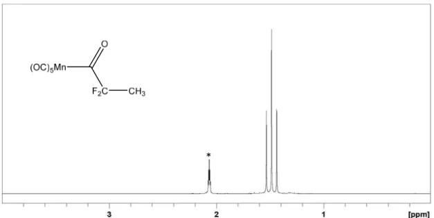
cobalt(II) acetylacetonate, although the Mn‐C bond dissociation enthalpy (BDE) are higher (42 to 54 kcal∙mol‐1 for manganese(I) family vs. 22 to 31 kcal∙mol‐1 for the
cobalt(II) family). One of the objectives of this thesis deals with the preparation of pentacarbonyl manganese complexes that are models of the dormant chains obtained by the OMRP of VDF with these manganese systems, and to measure experimentally their bond dissociation energies. It is therefore of interest to review the synthesis and properties of alkylpentacarbonylmanganese(I) complexes.
1.2. Metal carbonyl complexes
Metal carbonyls are coordination complexes of transition metals which bear carbon monoxide ligands. The family of metal carbonyls has been known for more than one century and is an important one in inorganic and organometallic chemistry. This is due to the interest in the structures, applications to organic and organometallic synthesis and indispensable role of these compounds as catalysts or catalyst precursors, such as in hydroformylation[108], in Reppe chemistry[109] and in the Mond process[110]. Thestability of metal carbonyls with oxidation states that are nil (neutral metal carbonyls) or even negative (anions) is produced by the notable ability of CO to give π‐backbonding. A wide diversity of mixed complexes bearing carbonyls and other ligands such as phosphines, cyclopentadienyls, arenes or other unsaturated hydrocarbon ligands are also accessible.
Metal carbonyl complexes are not present in nature, except for a few curious examples such as in the Galactic Center where monoxide vibrations of iron carbonyls in interstellar dust clouds were detected.[111] Iron carbonyl clusters were also observed in Jiange H5 chondrites, a non‐metallic stony meteorites that have not been altered due to melting or differentiation of the parent body identified by Fourier‐transform infrared spectroscopy (FTIR). Four infrared bands were identified as the terminal and bridging carbon monoxide ligands.[112]
1.2.1.
Structure and bonding
The low‐nuclearity binary metal carbonyls complexes obey the 18‐electron rule if one electron pair is counted from each CO, conferring a certain stability, except for the 17‐electron radical [V(CO)6], the structure of which is stabilized by the octahedralgeometry and steric crowding that contributes to prevent radical‐type reactions and dimerization. Other complexes such as [Mn(CO)6]+ complex obey the 18‐electron rule
and is stabilized for the same structural reasons, metal carbonyl cations being otherwise unstable. The transition metal‐carbon bond can be explained by the Dewar‐Chatt‐ Duncanson model.[113‐115] The bond strength is attributed to the π‐backbonding, which is possible by the mixing of the highest occupied atomic orbital (HOAO) of the metal atom with the lowest unoccupied molecular orbital (LUMO) of CO, see Scheme 11.[116] This kind of bonding requires that the metal possesses d‐electrons and is in a relatively low oxidation state. A σ‐bond originates from an overlap of the C‐O nonbonding (or weakly anti‐bonding) sp‐hybridized electron pair that is mostly localized on the carbon atom of the CO ligand with a blend of d‐, s‐, and p‐orbitals of the metal atom.
‐ 27 ‐
Scheme 11. Sigma bond (left) and “π‐backbonding” (right) in metal carbonyl complexes.
The high‐nuclearity metal‐carbonyl clusters [M6(CO)16] and beyond often escape
the 18‐electron rule to obey Wade’s rules.[117] Thus, mononuclear neutral metal
carbonyls are known for the metals that have an even number of d electrons, whereas neutral dimers with a single metal‐metal bond are known for metals that have an odd number of d electrons. Metal‐carbonyl clusters are mainly known in the iron, cobalt and nickel groups. They are all the more stable as one goes down in the columns of the periodic table because the strength of the metal‐metal bond increases in this direction.
1.2.2.
Physical characteristics
Mononuclear carbonyl complexes are usually colorless or pale‐yellow volatile liquids or solids that are flammable and toxic. However, vanadium hexacarbonyl, the uniquely stable 17‐electron metal carbonyl, is a blue‐black solid. Di‐ and polymetallic carbonyls usually are more intensely colored. For instance, triiron dodecacarbonyl [Fe3(CO)12] forms dark green crystals. The crystalline metal carbonyls can be normally
purified under vacuum, although this process is rarely accompanied by degradation. Metal carbonyls are generally soluble in non‐polar and polar organic solvents such as carbon tetrachloride, benzene, diethyl ether, acetone or glacial acetic acid and some cationic or anionic salts of metal carbonyls are soluble in water or alcohols.
1.2.3.
Applications
In organometallic chemistry, metal carbonyls are precursors for the preparation of other organometallic complexes, commonly from their anionic derivatives. Numerous anionic derivatives of metal carbonyl have been synthesized for almost a century, allowing to make some alkyl metal carbonyl complexes via nucleophilic substitution or another reaction involving an electrophilic molecule (e.g. reaction of a nucleophile with an acid derivate). Metal carbonyl anions are generally used as sodium salts in a tetrahydrofuran solution. They are usually prepared by reduction of binuclear or trinuclear (depending on the metal) metal carbonyl derivatives. In this work, we will focus on manganese carbonyl derivatives synthesized from manganese carbonyl.
1.2.4.
Techniques of characterization
Because the carbonyl ligands are firmly bonded to transition metals, the variations of the frequency of the strong infrared carbonyl absorption (around 2000 cm–1 for
terminal CO) allow to measure the electronic effects of the other ligands. The C‐O vibration frequency is related to the strength of carbon‐oxygen bond, and also related inversely to the strength of the π‐backbonding between the metal and carbon, depending on numerous factors such as the nature of metal, the coordination number or the oxidation state. In addition, the number of vibrational modes can be predicted by group theory. Carbonyl compounds can also be characterized by elemental analysis, NMR (13C, 17O and the metal nuclei if their nuclear spin is non‐zero), mass spectroscopy
‐ 29 ‐
1.2.5.
Manganese carbonyl complexes
The history of organometallic chemistry of manganese is not particularly extensive, unlike the organometallic chemistry of most other transition metals. There are only some incomplete and unproven reports of phenylmanganese species in the late 1930s and early 1940s, but the real development of the organometallic chemistry of manganese occurred during the 1950s. Hence, the origins of organomanganese chemistry are found in the time following the discovery of ferrocene, and expansion of this area has been in step with the rapid development of modern organometallic chemistry.[118] Dimanganese decacarbonyl was the first organometallic compound of
manganese to be isolated and characterized.[119]
1.2.6.
Dimanganese decacarbonyl
Dimanganese decacarbonyl, [Mn2(CO)10], is a metal carbonyl cluster composed of
two manganese atoms and ten carbonyl ligands with a manganese‐manganese bond between these two metallic atoms. It obeys the 18‐electron rule with ten electrons that come from the carbonyl ligands, and eight electrons coming from the two metal centers (3d7 and the shared electron of the Mn‐Mn bond).
1.2.6.1. Structure, physical and chemical properties
[Mn2(CO)10] is a volatile yellow compound, stable as a solid at room temperature inthe dark. It decomposes at room temperature over several months in contact with atmospheric oxygen giving a dark solid (manganese oxide). It is soluble in all common organic solvents, but not in water. In solution, it is more sensitive and it reacts quickly with oxygen to give manganese oxide. It can also easily dissociates under an inert atmosphere both thermally (∼60−90 °C)[120] and photolytically in solution, even at room
Scheme 12. Thermal or photolytical manganese carbonyl dissociation. The molecular structure of manganese carbonyl was determined by Churchill et al. in 1981 by single‐crystal X‐ray diffraction.[121] It is composed of two square pyramidal Mn(CO)5 groups linked with a metal‐metal bond. The overall molecule thus belongs to
the point group D4d, which is an uncommon symmetry shared with S2F10.[122] The
Mn−Mn bond dissociation enthalpy (BDE) is rather low (36.7±0.4 kcal∙mol‐1) and
decreased upon substitution of CO with other ligands.[123,124]
1.2.6.2. Synthesis
This compound was first obtained by the reduction of manganese iodide with a Grignard reagent and under a carbon monoxide atmosphere in 1949 by Hurd et al.,[119] however it was first isolated by reducing manganese iodide using magnesium in the presence of copper and under a carbon monoxide atmosphere by Brimm et al.[125]allowing to report the full characterization of this compound. Nevertheless, a meager yield (1%) was obtained by this synthetic pathway. Previously, Mond et al.[126] tried to
obtain [Mn2(CO)10] from pyrophoric manganese under a carbon monoxide atmosphere
(500 bar) and 450 °C but without any results. In 1958 it was shown that it can be synthesized through reaction of manganese chloride, a phenylmagnesium halide and CO in diethyl ether with 10% yield.[127]
The best method of synthesis of [Mn2(CO)10] was described by Podall et al.[128]
employing an aluminum alkyl as the reducing agent leading to 55% yield. Then, Calderazzo[129] proposed a simplified procedure for this process which produced
[Mn2(CO)10] in 48% yield. Another efficient synthetic pathway (but leading to 30% yield)
was proposed in 1965 employing manganese(II) chloride with sodium benzophenone ketyl with carbon monoxide under pressure (200 bar).[130]
‐ 31 ‐
It is also possible to synthesize manganese carbonyl by a low‐pressure route starting from (methylcyclopentadienyl)tricarbonylmanganese with sodium metal in diglyme (dimethyl ether of diethylene glycol) solution under a carbon monoxide atmosphere.[131] Although this synthetic pathway does not lead to a high yield (15‐20%),
it is easy to implement, does not use high pressures of carbon monoxide, and the starting materials are inexpensive. In fact, this is the synthetic pathway most used for commercially available manganese carbonyl.
1.2.6.3. Reactivity
[Mn2(CO)10] reacts directly with halogens, X2, through the scission of metal‐metal
bond to lead to [Mn (CO)5X],[132] but the main reactivity patterns involve the manganese
pentacarbonyl radical or the pentacarbonylmanganate ion, generally obtained in contact with an alkali metal.
As shown before, manganese pentacarbonyl radical can be formed by thermolysis or photolysis. In contrast to thermolysis, photolysis involves two competitive processes: the cleavage of manganese‐manganese bond, as well as loss of CO.[133] The radicals
formed by thermolysis are efficient abstractors of halide from RCCl3 compounds,[134] and
hence serve to initiate selective hydrogenolysis of such halides in the presence of good hydrogen donors[135] or addition to activated alkenes.[136] The pentacarbonylmanganate ion, [Mn(CO)5]‐, is usually obtained by reduction of manganese carbonyl with a sodium amalgam in THF as shown in Scheme 13.[130,132,137,138] However, the resulting solution is contaminated with approximately 10% [(CO)5Mn‐Hg‐ Mn(CO)5].[137] Other reagents can be used to obtain clean pentacarbonylmanganate ion
such as a sodium‐potassium metallic liquid alloy (NaK) in THF, providing mostly K[Mn(CO)5],[139] potassium tri‐sec‐butylborohydride, or lithium triethylborohydride,
which affords clean Li[Mn(CO)5].[140]


![Figure 11. Pictures of the evolution after the addition of 1‐bromoethyl acetate to the K[Mn(CO) 5 ] solution.](https://thumb-eu.123doks.com/thumbv2/123doknet/2973035.82762/76.892.134.767.200.450/figure-pictures-evolution-after-addition-bromoethyl-acetate-solution.webp)
![Figure 12. Pictures of the evolution of the solution by the addition of DFAA to the K[Mn(CO) 5 ] solution](https://thumb-eu.123doks.com/thumbv2/123doknet/2973035.82762/104.892.194.705.710.945/figure-pictures-evolution-the-solution-addition-dfaa-solution.webp)
![Figure 24. Pictures of the evolution after the addition of TFAA to the K[Mn(CO) 5 ] solution.](https://thumb-eu.123doks.com/thumbv2/123doknet/2973035.82762/113.892.156.745.162.451/figure-pictures-evolution-after-addition-tfaa-mn-solution.webp)