To cite this version :
Coppey, Nicolas
and Noé, Laure and Monthioux, Marc and Caussat,
Brigitte
Decorated carbon nanotubes by silicon deposition in fluidized
bed for Li-ion battery anodes (2013) International peer-reviewed journal.
Vol. 91 (n° 12). pp. 1491-2496. ISSN 0263-8762
O
pen
A
rchive
T
OULOUSE
A
rchive
O
uverte (
OATAO
)
OATAO is an open access repository that collects the work of some Toulouse researchers
and makes it freely available over the web where possible.
This is an author’s version published in :
http://oatao.univ-toulouse.fr/9312
Official URL :
https://dx.doi.org/10.1016/j.cherd.2013.01.002
Any correspondence concerning this service should be sent to the repository administrator :
Decorated
carbon
nanotubes
by
silicon
deposition
in
fluidized
bed
for
Li-ion
battery
anodes
Nicolas
Coppey
a, Laure
Noé
b,
Marc
Monthioux
b,
Brigitte
Caussat
a,∗aUniversitédeToulouse,LaboratoiredeGénieChimique,ENSIACET/INPToulouse/UMRCNRS55034,alléeEmileMonso,BP44362,
31432ToulouseCedex4,France
bCEMES,UPRCNRS8011,29rueJeanneMarvig,BP94347,31055ToulouseCedex4,France
a
b
s
t
r
a
c
t
Multi-walledcarbonnanotubesGraphistrength®
weredecoratedwithsiliconbyFluidizedBedChemicalVapor Depo-sition.Theabilitytofluidizeofthesenanotubesformingball-shapedjumblesofseveralhundredsofmicronsin diameterandthatofthefinalCNT-Siballswasfirststudied.Theseballsrevealtofluidizewithcharacteristicsof Geldart’sgroupAparticles,i.e.withoutbubblesandwithhighbedexpansion.CoatingexperimentsfromsilaneSiH4
wereperformedat500◦Cinthe30–60wt.%rangeofsilicondeposited.SEMandTEMimagingrevealsthatthe
nano-tubesarecoatedbysiliconnanoparticlesuniformlydistributedfromtheperipherytothecenteroftheballsforthe wholeconditionstested.On-lineacquisitionofkeyprocessparametersevolutionshowsthatthematerialremains fluidizable,evenforlargeproportionsofsilicondeposited.TheSauterdiameterandthetapped,untappedand skele-tondensitiesofballsincreasewiththepercentageofsilicondeposited,whereastheirspecificsurfaceareadecreases duetotheprogressivefillingoftheporesbythedeposit.Thiscompositematerialisapromisingcandidateasanode toreplacegraphiteinlithium-ionbatteries.
Keywords: CVD;Fluidization;Carbonnanotubes;Silicon;Silane;Li-ion
1.
Introduction
Inthecontextofhighdemandforenergyinmobiledevices, numerous studies concern the lithium-ion cell technology. Lithiatedcobaltoxideandgraphiterespectivelyusedas cath-odeandanodematerialcouldbereplacedbynanostructured composites, inorder toimprove safety,power density and energydensity,foralwayslowercost(ArmandandTarascon, 2008). Considering the poor energy density of graphite as anodematerial,siliconisagood candidatewitha theoret-icalcapacitytentimeshigher,but ithastofacetwomajor problems: arapid fading ofthe capacity and an increased polarizationathighercurrentrate(ObrovacandChristensen, 2004; Kasavajjula et al., 2007). Vertically aligned or ran-domlynetworkedcarbonnanotubesornanofibershavebeen exploredasasupportforsilicon(Chenetal.,2011;Cuietal., 2009,2010;WangandKumta,2010).Authorsoftenuse sputter-ingorconventionalCVD(ChemicalVaporDeposition)tocoat thecarbonsupportbysilicon.
∗ Correspondingauthor.Tel.:+33534323632;fax:+33534323697.
E-mailaddress:[email protected](B.Caussat).
OurworkisbasedontheFluidizedBedCVD(FBCVD) pro-cess,whichisparticularlyefficienttouniformlycoatpowders byvariousmaterials.Yuetal.(2006)haveshownthatcarbon nanotubescanbefluidizedundertheformofagglomerates andthattheirfluidizationwassmoothandhighlyexpanded, thuspresentingcharacteristicsofGeldart’sgroupAparticles. SuchgroupAparticlescorrespondtosmallsizeandlow densi-tiespowders.Theyexhibitanon-bubblingfluidizationregime withhighfluidizedbedexpansion(Geldart,1973).
Inapreviousstudyofourgroup,siliconFBCVDon agglom-eratesofsubmicronic TiO2 particles hasbeen investigated,
showingthatusingspecificoperatingconditions,siliconcan beuniformlydepositedasnanodotsonthewholepowder sur-face(Cadoretetal.,2010).Theseconditionshavebeenrecently appliedtodepositsiliconnanoparticlesonthewholesurface ofmulti-walledcarbonnanotubesagglomerates.DetailedSEM (ScanningElectronicMicroscopy)andTEM(Transmission Elec-tronicMicroscopy)analysesofthemorphology,diameterand number ofthedepositedsiliconnanoparticleshavealready
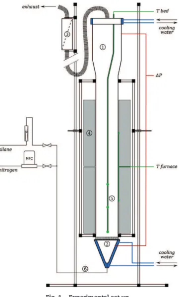
Fig.1–Experimentalsetup.
beenpresentedelsewhere(Coppeyetal.,2011).Thepresent articlefocusesonthefluidizationabilityandphysical charac-teristicsoftheseagglomeratesofnanotubesbeforeandafter CVDtreatmentandontheFBCVDprocessbehavior.The exper-imentalFBCVDequipmentallowingthedepositionofsilicon fromSiH4isfirstdescribed.Thenthecharacteristicsofthe
car-bonnanotubesandthemethodsofcharacterizationemployed aredetailed.Theresultsobtainedarefinallypresentedand discussed.
2.
Experimental
The experimental equipment is presented in Fig. 1. It consisted first in a vertical cylindrical stainless steel col-umn (referenced 1 in Fig. 1), 0.083m ID and 1m high. At
the bottom of the column, a perforated steel plate2
pro-vided a homogeneous gas distribution and its flange was cooled by water to avoid any silane premature decompo-sition. At the exit, a high performance HEPA13 filtration cartridge3allowedcollectingtheelutriatedparticles.The
reac-torwasexternallyheatedbyatwo-zoneelectricalfurnace4
and its wall temperatureswere controlledbytwo thermo-couplesconnectedtoPIDregulators.Severalthermocouples were also placedinto avertical tube of6mm indiameter insidethereactor5tomonitorthe axialprofileof
tempera-ture.Experimentswere performedatatmosphericpressure. Electronic grade silane SiH4 and N50 nitrogen (from Air
Liquide) were supplied6 to the bottom ofthe bed through
respectively a ball rotameter (GT1355, Brooks Instrument) and a mass flow meter (FC7710CD, Aera). Uncertainties of ±5%couldaffectthesilaneflowratemeasuredandthenthe amountsofinjectedsilane.Adifferentialfastresponse pres-suresensor(LPX5480,Druck)measuredthetotalpressuredrop across thebed.Anabsolutepressure sensorallowed moni-toring thetotal pressurebelowthe distributor.ADasyLab®
systemenabledtheon-lineacquisitionofthedifferential pres-sureandFBtemperatures. Hydrodynamicmeasurementsat ambienttemperaturewereperformedinaglasscolumn5cm IDequippedwiththesamedifferentialpressuresensorand filteringcartridge.
The hydrodynamic behaviorof powders inthe fluidiza-tion column was analyzedby classically measuring(i) the pressure dropof the gascrossing the bed and (ii) the bed expansion,asafunctionofgasvelocity(KuniiandLevenspiel, 1991).
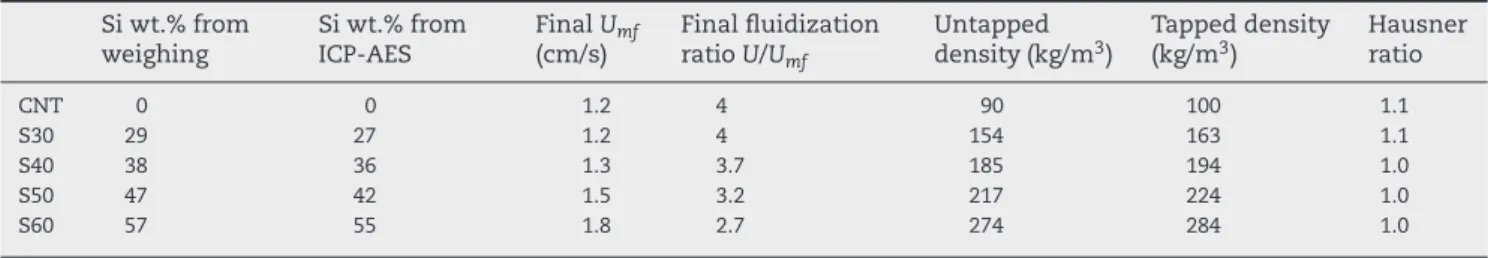
Multi-walled carbon nanotubes Graphistrength® from
Arkema (called CNT in the following), were used without anypurificationtreatment. Theiraverageexternaldiameter is closeto12nm and someironcatalyst nanoparticles are present,ascanbeseeninFig.2.Theyareagglomeratedunder theformofroughlysphericalballsasshowninFig.2a.The SauterdiameteroftheseCNTballsisof340mmandtheir skele-taldensityisequalto1980kg/m3.Theirspecificsurfaceareais
closeto230m2/g,asmeasuredbyBETmethod.TheirHausner
ratioisequalto1.1,indicatingalowcohesivity.
Forthehydrodynamicstudy,35gofCNTwereused lead-ingtoafixedbedheightof24cm.EachFBCVDexperimentwas performedwith100gofCNT,whichcorrespondstoafixedbed heightof18.4cm.AspreviouslystudiedbyCadoretetal.(2010), theinletmolarfractionofsilaneandthebedtemperaturewere choseninordertoworkinconditionsofhighchemical limi-tation,i.e.inconditionsforwhichtheheterogeneousreaction rateislowincomparisonwiththegaseousspeciestransport, inordertoexaltgaseousspeciesdiffusionthroughthe poros-ityoftheCNTballs.Ouraimwasclearlytoobtainuniform depositsontheentireCNTsurface,fromtheperipherytothe centeroftheCNTballs.Forallexperiments,wechosetokeep constant thereactortemperature at500◦C,the fluidization
ratioUg/Umfat4andtheinletSiH4concentrationat7.5vol.%.
Themassofdepositedsiliconwasthencontrolledbyrun dura-tion.Weselectedtheminordertocoverthe30–60wt.%range ofsilicondeposited,accordingtoliteratureresultsonCNT/Si anodematerials(Sietal.,2010).
TheCNTballsbeforeandafterCVDwereanalyzedas fol-lows:
• themassofSidepositedwasmeasuredbybedweighing andbyInductivelyCoupledPlasma-AtomicEmission Spec-troscopy(ICP-AES)chemicalanalysis,onaThermo-Fisher iCAP6300,
• thepowdermorphologywasobservedby(i)Scanning Elec-tronMicroscopy(SEM)onaHitachiTM3000onwhichenergy dispersiveX-rayspectroscopy(EDS)wasalsoperformed,(ii) FieldEffectGunSEM(FEG-SEM)usingaJeol6700S,and(iii) TransmissionElectronMicroscopy(TEM)onaPhilipsCM30, LaB6gun,operatedat150kVtominimizedamaging
irradi-ationeffects,
• the laser scattering size analysesof CNTballs after air-dispersionunderanoverpressureof0.1barwereperformed
Fig.2–(a)SEMview,(b)FEG-SEMviewand(c)TEMviewofGraphistrenght®
CNTballs. withaMalvernMasterSizer2000setup.Eachmeasurement
correspondstoanaveragevaluecalculatedover5runs, • the BET surface area was measured by a physisorption
analyzerMicromeriticsASAP2010,after2hofdegassingat 200◦C,
• theskeletondensityofballswasmeasuredbyhelium pyc-nometryonaMicromeriticsAccupyc1330,
• tappedanduntappeddensitiesweredeterminedona pow-dertesterPT-EHosokawaMicron,witha100cm3cylindrical
vial tapped50 timesbyminuteduring4min.Each mea-surementcorrespondstoanaveragevaluecalculatedover 3runs.
3.
Results
and
discussion
3.1. HydrodynamicstudyofthefluidizationofCNT andofCNT-Sicomposites
Inafirststep,theabilityoftheuntreatedCNTtofluidizewas studiedintheglasscolumnusingN2asfluidizationgas.The
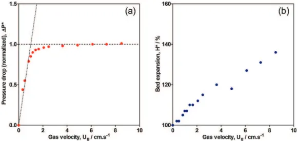
bedexpansionandthebedpressuredropweremeasuredat decreasinggasvelocity,becauseofthepossibleexistenceof apressure overshootatincreasinggasvelocitydueto par-ticleside wallsfriction and particle cohesionforces which canaffectthetransitionbetweenfixedbedandfluidizedbed (WeberandHrenya,2007).
Theresultsare reportedinFig.3.1P* isthenormalized pressuredropcorresponding tothemeasured bedpressure dropdividedbythetheoreticalone(i.e.theweightofparticles
perunitsurfaceareaofcolumn)andH*isthedimensionless expansion,correspondingtotheratiobetweentheexpanded bedheightandthefixedbedheight.
Thepressuredropcurveclearlyshowsthatthefluidization ofCNTwasachieved.Indeed,thefluidizationplateauat1P*=1 canbedrawneasilyandtheminimumfluidizationvelocity
Umfwasdeterminedasequalto1.2cm/s,attheintersection
betweentheplateauandthefixedbedzone,accordingtothe methodofDavidsonandHarrison(1963).
The expansion curve indicates a linear increase of the expandedbedheightwithgasvelocity,reachinghighvalues (>1.3)forgasvelocitieshigherthan6Umf.Thebedwasfound
toexpandevenforUg<Umf.Thisbehaviorhasalreadybeen
observedbyprevious authors(Wangetal.,2007;Zhuet al., 2005),andisbelievedtobeadistinctfeatureofnanoparticle agglomeratesfluidization.Visually,thefluidizationoccurred homogeneously,i.e.withoutgasbubbles,forfluidizationratios
Ug/Umflower than8. So,asfoundbyYuetal.(2006),these
resultsindicatethatthefluidizationoftheseCNTballspresent characteristics of Geldart’s group A powders. From Ug/Umf
equalto8andbeyond,sluggingoccurredwithhigher fluctua-tionsofthebedheight,certainlyduetowallseffectsinduced bytherelativelylowcolumndiameter(KuniiandLevenspiel, 1991).
ItisworthnotingthatthedeterminationofUmfwasalso
attemptedfrommeasurementsofthestandarddeviationsof bedheightfluctuationsvs.decreasinggasvelocities,butno resultwasobtainedbecauseoflowvaluesofheight fluctua-tionsduetotheabsenceofbubbles.
Table1–MaincharacteristicsofCNT-Siballs. Siwt.%from weighing Siwt.%from ICP-AES FinalUmf (cm/s) Finalfluidization ratioU/Umf Untapped
density(kg/m3) Tapped(kg/m3)density Hausnerratio
CNT 0 0 1.2 4 90 100 1.1
S30 29 27 1.2 4 154 163 1.1
S40 38 36 1.3 3.7 185 194 1.0
S50 47 42 1.5 3.2 217 224 1.0
S60 57 55 1.8 2.7 274 284 1.0
Inasecondstep,theabilitytofluidizeoftheCNT-Si com-positeballswasalsostudiedintheglasscolumn,aftereach CVDexperiment.Thepressuredropcurves(notshown) indi-catethatalltheCNT-Sicompositeballswerefullyfluidized withaclearhorizontalplateauat1P*=1.Theminimum flu-idizationvelocitiesUmfofthecompositesS30–S60aregivenin
Table1below.AprogressiveincreaseofUmfwasobservedfrom
runS40,whichcanbeexplainedbyanincreaseofthemean diameteranddensityoftheballsduetosilicondeposition,as detailedinthenextsection.Abedexpansionatgasvelocities lowerthanUmfwasstillobserved,indicatingthattheCNT-Si
ballsalsobehaveasnanoparticleagglomerates.Onlyforthe S60composite,thepresenceofbubbleswasobservedfor flu-idizationratioshigherthan2,leadingtohigherfluctuations oftheexpandedbedheight.Suchbehaviorischaracteristicof Geldart’sgroupBparticles.
Itisworthnotingthatthemorphologyandmeandiameter oftheballs wasunchangedaftertheirfluidization suggest-ingthattheyarenotsubjecttoattrition,probablythanksto theirentangledstructure(Fig.2b)andtothehighmechanical resistanceofCNT.
ThehydrodynamicbehavioroftheseCNTandCNT-Siballs inafluidizedbedcolumnisthenconvenient,evenwithsilicon depositedupto50wt.%.Therefore,thermalandmass trans-fersduringsiliconFBCVDexperimentsshouldbehighenough toensurereproducibleanduniformdeposits.
3.2. FluidizedBedCVDofsilicononCNT
Thetemporalevolutionofbedtemperaturesandbedpressure dropduringFBCVDexperimentswassimilarforeachrun.A characteristicexample,correspondingtorunS60 ofTable1
below,isshowninFig.4.
ThankstoPIDregulators,thebedtemperatureswere main-tainedcloseto500◦Cduringthecoatingstep.Beforesilane
Fig.4–Temporalevolutionofthereactortemperaturesand normalizedbedpressuredropforrunS60(T1:6cmabove thedistributor,T2:22cm,T3:35cm).
injection,thebedofCNTwasisothermal(differencesbetween T1 and T2 lower than 2◦C), proving that fluidization was
achieved.DuringCVD,athermalgradient(max.valueof10◦C)
appeared into the bed proportional to run duration. This behaviorisprobablyduetoaprogressiveincreaseofthe mini-mumfluidizationvelocityUmfoftheCNT-Siballs,aspreviously
detailed.Sinceweworkedatconstantinletgasflowrate,this ledtoaprogressivedecreaseofthefluidizationratiosUg/Umf
ascalculatedinTable1,andthenprobablytoaless isother-malbed.TheT3temperaturecorrespondstoathermocouple locatedabovethebed.Itincreasedduringdepositionbecause thefurnacehadtoprovidemoreenergytothereactordueto thelowerfluidizationqualityandtothebedweightincrease.
Fig.4alsoshowsthatthebedpressuredrop(normalizedwith theinitialbedweight)increasedproportionallytotheweight ofdeposited silicon,confirming that thebed was fully flu-idizedallalongrunduration.Asaconsequence,theweight ofdepositedsiliconwasdeducedfromthebedpressuredrop measurements.Ameanerrorof5%wasfoundbetweenthese valuesandthosededucedfrombedweighing.
AsdetailedinTable1,theyarethemselvesverycloseto the values obtained by ICP-AES analysis. The tapped and untapped densities logically increase with the percentage ofdeposited silicon. TheHausnerratio ofthe CNT-Si balls remainscloseto1forallsamples,confirmingtheirlow cohe-sivityandthentheirabilitytofluidize.
Fig.5indicatesthattheSauterdiameteroftheCNT-Siballs remains unchanged for 30 and 40wt.% ofSi, and tendsto increaseforhighervalues,probablybecauseofaninflationof theirflexiblestructureinducedbythedeposition.Theflexible natureoftheCNT-SiballsisapositivepointfortheLi-ion bat-teryapplication,sincethelithiuminsertion/extractioncycles can lead tomechanical failures of the electrodes (Obrovac andChristensen,2004;Wuetal.,2012).TheBETspecific sur-facearealinearlydecreaseswhenincreasingthedepositedSi
Fig.5–EvolutionoftheSauterdiameter,BETsurfacearea andskeletondensityofCNT-Siballswiththeweight percentageofdepositedsilicon.
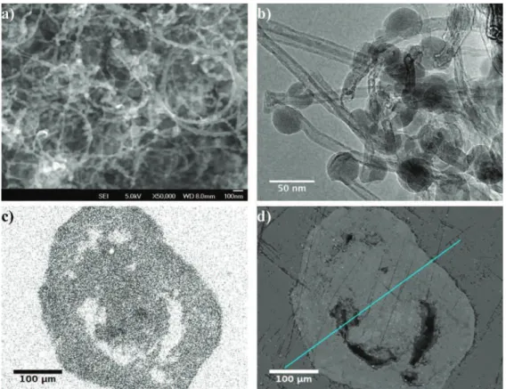
Fig.6–(a)FEG-SEMand(b)TEMviewsofCNT-Siballs,(c)SimappingbyEDSand(d)correspondingSEMviewofahalf-cut ballembeddedinepoxyresin,afterrunS60.
weight,certainlyduetoafillingoftheporousvolumebythe silicondeposit.Fortheapplication,acompromisewillthen havetobefoundbetweentheweightofdepositedsiliconand theaccessibilityofsilicontotheLi+ions(Wuetal.,2012).The
skeletondensityincreasesproportionallywiththepercentage ofdepositedsilicon.Thesevaluesareingoodagreementwith theoreticalonescalculatedfromtheCNTandsilicon individ-ualskeletondensitiesforeachSipercentage,confirmingthe validityoftheselatters.
Fig.6apresentsaFEG-SEMviewofCNT-Sicompositesafter runS60,thesemorphologiesaretypicalofthe whole sam-ples obtained. The network ofnanotubes appearsbut the CNTsurfaceexhibitsarough aspect. Thisisduetosilicon nanoparticles (NPs)homogeneously distributed on the sur-faceofCNT.ThepresenceofSiNPsisconfirmedbytheTEM view of Fig. 6b. SiNPs present a flattened sphericalform, withasharp sizedistributionaround30nm.TheNP diam-etertendstoincrease withtheSi percentagedeposited.In order to evaluatethe distribution ofsilicon into the balls, EDSmappingsofsilicon(Fig.6c)wereperformedonpolished crosssections ofCNT-Siballs embeddedinepoxy resin,as showninFig.6d.SomepartsoftheballsareemptyofCNT andthencouldnotemitenergyfromtheX-raybombardment. OntheSimap,thiswasconfirmedbyawhitezone,without depositedSi.Themainresultisthatauniformsilicon depo-sitionwasobservedfromtheperipherytothecenterofthe balls,meaningthatthe coatingoccurredonthe whole sur-face developedbythe CNT.This observationwas repeated onnumerousCNT-SiballsforalltheSipercentagesstudied. Thisresult provesthat as wished forthe operating condi-tions tested, thedeposition reactionisthe limiting stepof theprocess,notthegasdiffusionintotheporesoftheCNT balls.
4.
Conclusion
Multi-walled carbon nanotubes (CNT) Graphistrength®
, assembledinballsofseveralhundredsofmicrons,were dec-oratedbyFluidizedBedChemicalVaporDeposition(FBCVD), without any purification treatment. Silicon was deposited within CNTballs from silane SiH4 thermaldecomposition.
A hydrodynamic study showed a homogeneous fluidiza-tion ofthe untreatedCNTbed withahigh bed expansion, characteristicofGeldart’sgroupApowders. AfterCVD,the abilitytofluidizeoftheCNT-Siballswasalsodemonstrated, withan increaseofthe minimumfluidization velocitydue toSideposition.ForCVDexperiments,variousrundurations were tested, leading to silicon contents in the 30–60wt.% range. Theinletmolar fractionofsilaneand the bed tem-peraturewerekeptconstantforallruns.Theywerechosen in order towork in conditions ofhigh chemical limitation to favor silicon deposition on all CNT surface. During the runs involving deposited silicon weight percentages lower than40%,thefluidizedbedwasisothermal,whereasasmall thermalgradientappearedathigherSipercentages,dueto adecreaseofthefluidizationratio.NumerousEDSmapping imagesofcross-sectionedCNT-Siballsprovedthattheentire surfaceofCNTwasuniformlycoatedbysiliconnanoparticles from the periphery to the center of the balls. The Sauter diameter,tapped,untappedandskeletondensitiesofCNT-Si balls increase with the deposited silicon content,whereas their specific surface area decreases.Further works are in progress about (i) CNT pre-treatments, aiming to preserve the specific surface area of the CNT-Si balls even at high silicon percentages and (ii) electrochemical tests of this nano-structured composite material as anodes of Li-ion batteries.
Acknowledgements
The authors acknowledge Arkema for supplying the Graphistrength® carbon nanotubes, M. Molinier and E.
PrévotfromLGC/INPT fortechnicalsupport,S.LeBlonddu PlouyfromTEMSCANforFEG-SEMimaging,C.ReyRouch,M.L. DeSolanandG.Raimbeauxfortheirhelpinthe numerous characterizations in the Process and Analysis Service at LGC/INPT.
References
Armand,M.,Tarascon,J.M.,2008.Buildingbetterbatteries. Nature451,652–657.
Cadoret,L.,Rossignol,C.,Dexpert-Ghys,J.,Caussat,B.,2010. ChemicalvapordepositionofsiliconnanodotsonTiO2
submicronicpowdersinvibratedfluidizedbed.Mater.Sci. Eng.B170(1-3),41–50.
Chen,P.-C.,Xu,J.,Chen,H.,Zhou,C.,2011.Hybridsilicon-carbon nanostructuredcompositesassuperioranodesforlithiumion batteries.NanoResearch4,290–296.
Coppey,N.,Noe,L.,Monthioux,M.,Caussat,B.,2011.Fluidized bedchemicalvapordepositionofsilicononcarbonnanotubes forLi-ionbatteries.J.Nanosci.Nanotechnol.11(9),
8392–8395.
Cui,L.-F.,Yang,Y.,Hsu,C.M.,Cui,Y.,2009.Carbon-silicon core–shellnanowiresashighcapacityelectrodeforlithium ionbatteries.NanoLett.9,3370–3374.
Cui,L.F.,Hu,L.,Choi,J.W.,Cui,Y.,2010.Light-weight free-standingcarbonnanotube-siliconfilmsforanodesof lithiumionbatteries.ACSNano4(7),3671–3678.
Davidson,J.F.,Harrison,D.,1963.FluidizedParticles.Cambridge UniversityPress.
Geldart,D.,1973.Typesofgasfluidization.PowderTechnol.7(5), 285–292.
Kasavajjula,U.,Wang,C.,Appleby,A.J.,2007.Siliconanodesfor Li-ionbattery.J.PowerSources163,1003–1039.
Kunii,D.,Levenspiel,O.,1991.FluidizationEngineering,2nded. Butterworth-HeinemannLtd.,Newton,MA,USA.
Obrovac,M.N.,Christensen,L.,2004.Structuralchangesinsilicon anodesduringlithiuminsertion/extraction.Electrochem. SolidStateLett.7(5),A93–A96.
Si,Q.,Hanai,K.,Ichikawa,T.,Hirano,A.,Imanishi,N.,Takeda,Y., Yamamoto,O.,2010.Ahighperformancesilicon/carbon compositeanodewithcarbonnanofiberforlithium-ion batteries.J.PowerSources195(6),1720–1725.
Wang,W.,Kumta,P.N.,2010.Nanostructuredhybrid silicon/carbonnanotubeheterostructures:reversible high-capacitylithium-ionanodes.ACSNano4(4),2233–2241. Wang,X.S.,Rahman,F.,Rhodes,M.J.,2007.Nanoparticle
fluidizationandGeldart’sclassification.Chem.Eng.Sci.62, 3455–3461.
Weber,M.W.,Hrenya,C.M.,2007.Computationalstudyof pressure-drophysteresisinfluidizedbeds.PowderTechnol. 177,170–184.
Wu,H.,Zheng,G.,Liu,N.,Carney,T.J.,Yang,Y.,Cui,Y.,2012. EngineeringemptyspacebetweenSinanoparticlesfor lithium-ionbatteryanodes.NanoLett.12,904–909. Yu,H.,Zhang,Q.,Gu,G.,Wang,Y.,Luo,G.,Wei,F.,2006.
Hydrodynamicsandgasmixinginacarbonnanotube agglomeratefluidizedbed.AIChEJ.52,4110–4123. Zhu,C.,Yu,Q.,Dave,R.N.,Pfeffer,R.,2005.Gasfluidization
characteristicsofnanoparticleagglomerates.AIChEJ.51, 426–439.