Direction des bibliothèques
AVIS
Ce document a été numérisé par la Division de la gestion des documents et des archives de l’Université de Montréal.
L’auteur a autorisé l’Université de Montréal à reproduire et diffuser, en totalité ou en partie, par quelque moyen que ce soit et sur quelque support que ce soit, et exclusivement à des fins non lucratives d’enseignement et de recherche, des copies de ce mémoire ou de cette thèse.
L’auteur et les coauteurs le cas échéant conservent la propriété du droit d’auteur et des droits moraux qui protègent ce document. Ni la thèse ou le mémoire, ni des extraits substantiels de ce document, ne doivent être imprimés ou autrement reproduits sans l’autorisation de l’auteur.
Afin de se conformer à la Loi canadienne sur la protection des renseignements personnels, quelques formulaires secondaires, coordonnées ou signatures intégrées au texte ont pu être enlevés de ce document. Bien que cela ait pu affecter la pagination, il n’y a aucun contenu manquant.
NOTICE
This document was digitized by the Records Management & Archives Division of Université de Montréal.
The author of this thesis or dissertation has granted a nonexclusive license allowing Université de Montréal to reproduce and publish the document, in part or in whole, and in any format, solely for noncommercial educational and research purposes.
The author and co-authors if applicable retain copyright ownership and moral rights in this document. Neither the whole thesis or dissertation, nor substantial extracts from it, may be printed or otherwise reproduced without the author’s permission.
In compliance with the Canadian Privacy Act some supporting forms, contact information or signatures may have been removed from the document. While this may affect the document page count, it does not represent any loss of content from the document.
.
)Université de Montréal
Molecular Tectonics:
Supramolecular 20 Nanopatterning
of Surfaces by Self-Assembly
Par
Hui Zhou
Département de chimie
F acuIté des arts et des sciences
Thèse présentée à la F acuIté des études supérieures
en vue de l'obtention du grade de
_
__
.
__
...,,(."1'1' ,(1~~ .. c.., ••
Philosophiae Doctor (Ph. D.)
/
'
'
~
.
'~
'
"
~a.se e
'
,
.
. . 0.0 Ir ~
en chImIe
~
Grade conféré%
&
à compter du ~cu
.
co
u.
0
9 JU
I
l. 2009
enFévrier 2009
Université de Montréal
Faculté des études supérieures
Cette thése intitulée:
Molecular Tectonics:
Supramolecular 20 Nanopatterning
of Surfaces by Self-Assembly
Présentée par:
Hui Zhou
a été évaluée par un jury composé des personnes suivantes :
Andreea R. Schmitzer
James D. Wuest
Antonella Badia
Dmitrii
F.
Perepichka
J ean-Yves Lapointe
Président-rapporteur
Directeur de recherche
MelTlbre du jury
Examinateur extenle
Sommaire
Au cours des dernières années, la tectonique moléculaire a été utilisée comme une stratégie efficace dans la construction d'architectures supramoléculaires en trois dimensions (3D). Les éléments de construction utilisés dans cette stratégie, qui ont été appelés tectons, ont des géométries bien définies et de multiples substituants qui contrôlent l'association intermoléculaire en formant des interactions directionnelles, comme les liaisons hydrogène. Une nouvelle opportunité existe maintenant d'adopter cette stratégie pour créer des réseaux moléculaires bien définis en 2D à la surface de divers substrats, tels que le graphite. Dans cette thèse, nous décrivons une nouvelle série de tectons qui ont été délibérément conçus et synthétisés pour faire le nanopatterning de la surface du graphite pyrolytique hautement orienté (HOPG).
Pour comprendre les détails de l'adsorption moléculaire, de multiples méthodes de caractérisation et d'analyse ont été utilisées dans ce travail, y compris 1) l'examen direct de l'adsorption par STM (microscopie de balayage à l'effet tunnel); 2) la modification systématique de la structure de l' adsorbate pour analyser les conséquences sur l'organisation en 2D; 3) la comparaison de l'organisation observée en 2D avec celle favorisée dans les structures 3D déterminées par la cristallographie aux rayons X et 4) les calculs théoriques pour aider à révéler l'origine moléculaire de l'adsorption.
En particulier, notre étude a examiné l'effet de certains changements systématiques de la structure des molécules déposées, surtout la longueur, les groupes fonctionnels présents, la géométrie et la chiralité. Dans ces composés, des cœurs aromatiques comme le benzène,
le naphtalène et l'anthracène sont greffés à des espaceurs conjugués, y compris l'acétylène et arylacétylène, et sont liés également à divers groupes fonctionnels avec différentes capacités de s'engager dans des interactions intermoléculaires, notamment des groupes diaminotriazine, des acides carboxyliques et des esters correspondants. L'analyse des divers motifs d'assemblage obtenus a conduit à une compréhension plus profonde de l'interaction des adsorbates avec l'HOPo, des interactions inter-adsorbate et de l'importance relative des facteurs déterminant l'organisation observée.
Notre travail démontre les forces et les faiblesses de l'approche de la tectonique moléculaire pour régir l'assemblage moléculaire en 2D et en 3D. Certains aspects structuraux sont prévisibles, mais les interactions intermoléculaires que nous avons employées ne sont pas suffisantes pour positionner les adsorbates avec confiance, sans tenir compte de l'effet de la surface sous-jacente. Néanmoins, notre travail confirme que des molécules avec des structures bien définies, une forte affinité pour l'adsorption et une forte tendance de participer dans des interactions intermoléculaires directionnelles offrent une capacité importante pour structurer diverses surfaces à l'échelle du nanomètre.
Mots-clés: tectonique moléculaire, 2D nanopatteming, microscopie de balayage à effet tunnel (STM), l'auto-assemblage
Abstract
In recent years, molecular tectonics has been employed as an efficient strategy in the construction of supramolecular architectures in three dimensions (3D). The building blocks used in this strategy, which have been called tectons, have structures with well-defined geometries and multiple functional groups that control intermolecular association by forming directional interactions, su ch as hydrogen bonds. A new opportunity exists to adopt this strategy to create well-defined 2D molecular networks on the surfaces ofvarious substrates, such as graphite. In this dissertation, a series of new tectons have been purposefully designed and synthesized for nanopatteming surfaces, and their adsorption on highly oriented pyrolytic graphite (HOPG) has been thoroughly examined by scanning tunneling microscopy (STM).
To understand the details of molecular adsorption, multiple methods of characterization and analysis have been used in this work, including 1) direct examination of adsorption by STM, 2) systematic alteration of the structure of the adsorbate to reveal how the self-assembled 2D nanopattems changes, 3) comparison of the observed 2D nanopattems with those seen in 3D structures by X-ray crystallography, and 4) theoretical ca1culations to help disclose the origin of molecular adsorption.
Specifically, the tectons investigated herein incorporate systematic changes of molecular length, cores, functional groups, and molecular geometries. The basic cores, which are aromatic systems such as benzene, naphthalene, and anthracene, are grafted to conjugated linkers, including acetylene and arylacetylene, and to various functional groups
with different abilities to engage in intermolecular interactions, including diaminotriazine groups, carboxylic acids, and related substituents. The observation of diverse nanopatterns has led to adeeper understanding of 1) how the basic backbone interacts with surfaces, 2) how the functional groups modify the behavior of the backbone, and 3) how the formation of interadsorbate interactions further influences adsorption.
Our work demonstrates that rational 2D and 3D molecular assembly can be achieved and analyzed by an integrated approach using the tools of STM, X-raydiffraction, computation, and molecular synthesis. Furthermore, our work confirms that molecules with well-defined shapes and multiple sites that engage in strong directional interactions are a consistently productive source of new materials with properties not previously observed.
Key words: Molecular tectonics, 2D nanopatterning, scannmg tunneling mlcroscopy (STM), self-assembly
Acknowledgment
First of all, l would like to thank my advisor, Professor James D. Wuest, for his support, guidance, and understanding. During the process of my research, he introduced me to the field of supramolecular chemistry and surface science, helped me work things out when they appeared complicated, and also gave me the freedom to develop my own ideas. He encouraged me not to give up when l failed my first pre-doctoral exam, and l will never forget his smiling face when he heard that l passed all the exams eventually.
l am grateful to Wuest group members who have shared their scientific thoughts and experimental know-how, in particular Dr. Hung Dang, Cheng song Hu, Dr. Kenneth E. Maly, Eric Gaghon, -and Dr. Tao Tu. l would also like to thank Dr. Thierry Maris for his patient- crystallographic analysis of my crystals, which were rarely as ,good as he wanted them to be.
l would like to thank Dr. Ji-Hyun Daniel Yi and Prof. Antonio Nanci, who provided me guidance and support to work in the Laboratoire de Recherche sur les Tissus Calcifiés et Biomatériaux, allowing me to finish all my nanopatteming experiments using scanning tunneling microscopy (STM). l am grateful to Dr. Alain Rochefort for his quantum chemical Density Functional Theory (DFT) calculations. l would also like to acknowledge the work of all the staff at the Laboratoire de RMN, the Centre Régional de Spectrométrie de Masse, and the Laboratoire d'Analyse Élémentaire at the Université de Montréal.
l also give great thanks to my mother, who came in 2005 to Montréal, so far away from China, and took care of my son and cooked for me. Many thanks to my sister and two
brothers for their concem. l would also like to thank my son Boming, who gives me the reason and strength to live weil.
A very special thank you goes to my husband, Chengcan Wang, for his constant love, encouragement, and understanding. He gave up his career in China and decided to come to Montréal and start an entirely new life. With his company, l can never be al one or lost.
This dissertation is also dedicated to my father, who passed away in 1999. His love will be always with me.
Table of Contents
Sommaire ... .1
Abstract ... 111
Acknowledgment ... V Table of Contents ... VII Table of Figures ... XIII Table of Schemes ... XXVI Index of Tables ... XXVII List of Abbreviations ... XXVIII Chapter 1 1.1 1.2 Introduction ... 1
Supramolecular Chemistry and Self-Assembly ... 2
Crystal Engineering and Surface Nanopatteming ... .4
1.2.1 Hydrogen Bonding ... 5
1.2.1.1 Carboxyl Groups ... 6
1.2.1.2 Diaminotriazine Groups ... 7
1.2.1.3 Hydroxyl Groups ... .1 0 1.2.2 Metal Coordination ... 12
1.2.3 Van der Waals Interactions ... 13
1.3 Molecular Tectonics ... 13
1.4 Purpose of This Study ... 17
References ... 20 Chapter 2 2.1 2.2 2.3 2.4 Scanning Tunneling Microscopy (STM) ... 28
Introduction ... 29
Basic Principle of STM ... 30
STM Instrumentation ... 33
2.4.1 Gold ... 36 2.4.2 Graphite ... 37 2.5 STM Tip ... 41 2.6 Sample Preparation ... 42 2.7 Imaging Parameters ... 44 2.8 STM Image Analysis ... .45 References ... 48
Chapter 3 STM Study of the Adsorption of Tectons Bearing Diaminotriazine Substituents ... 53
3.1 Introduction ... 54
3.2 Design and Synthesis of Tectons ... 56
3.2.1 ~ynthesis ofTecton DAT-I ... 56
3.2.2 Synthesis of Tecton DAT-2 ... 57
3.2.3 Synthesis of Tecton DAT-3 ... 57
J 3.2.4 Synthesis of Tecton DAT-4 ... 59
3.3 STM Investigations and X-Ray Crystallography of Tectons DAT-I, DAT-2, DAT-3, and DAT-4 ... 61
3.3.] 2D Nanopattems Formed by Tecton DAT-l ... 61
3.3.2 3D Crystal Structure ofTecton DAT-l ... 70
3.3.3 2D Nanopattems Formed by Tecton DAT-2 ... 73
3.3.4 3D Crystal Structure ofTecton DAT-2 ... 76
3.3.5 2D Nanopattems Formed by Tecton DAT-3 ... 79
3.3.6 3D Crystal Structure of Tecton DAT-3 ... 81
3.3.7 2D Nanopatteming by Tecton DAT-4 ... 85
3.3.8 3D Crystal Structure ofDAT-4 ... 87
3.4 Summary ... 91
Chapter 4 STM Study of the Adsorption of Tetracarboxylic Acids Created by
Connecting Isophthalic Acid Units to Linear Spacers ... 99
4.1 Introduction ... l 00 4.2 Design and Synthesis of Tectons ... 104
4.2.1 Synthesis of Tecton TA-5 ... 104
4.2.2 Synthesis of Tecton TA-6 ... 105
4.2.3 Synthesis of Tecton TA-7 ... .106
4.2.4 Synthesis of Tecton TA-8 ... 108
4.3 STM Investigation of the Adsorption of Tectons BTA, TA-S, TA-6, TA-7, and TA-8 on Graphite ... 110
4.3.1 2D Nanopattems Formed by ::recton BTA ... 110
4.3.2 2D Nanopattems Formed by Tecton TA-6 ... 114
4.3.3 2D Nanopattems Formed by Tecton TA-5 ... 119
4.3.4 2D Nanopattems Formed by Tecton TA-7 ... : ... 122
4.3.5 2D Nanopattems Formed by Tecton TA-8 ... 126
4.4 DFT Calculations ... 129
4.5 Frustrated 2D Molecular Crystal1ization ... 131
4.6 Summary ... 135
References ... 136
Chapter 5 STM Study of the Adsorption of Tetraesters Created by Connecting Isophthalate Units to Linear Spacers ... 140
5.1 Introduction ... 141
5.2 Design and Synthesis of Tetraesters ... 143
5.3 STM Investigations and X-Ray Crystallography of Tetraesters TE-5, TE-6, TE-7, TE-8, and TE-9 ... 144
5.3.1 2D Nanopattems Formed by Tetraester TE-5 ... .144
5.3.2 3D Crystal Structures ofTetraester TE-5 ... 149
5.3.3 2D Nanopattems Formed by Tetraester TE-6 ... 152
5.3.5 2D Nanopattems Fonned by Tetraester TE-9 ... 160
5.3.6 3D Crystal Structures of Tetraester TE-9 ... ] 63
5.3.7 2D Nanopattems Fonned by Tetraester TE-7 ... 167
5.3.8 2D Nanopattems Fonned by Tetraester TE-8 ... .172
5.3.9 3D Crystal Structures of Tetraester TE-8 ... .177
5.3.10 Competitive Adsorption of Tetraesters on HOPG ... 181
5.4 Summary ... 185
References ... 188
Chapter 6 Chiral 2D Nanopatterns Created by Derivatives of Isophthalic Acid ... 191
6.1 Introduction ... 192
6.2 Design and Synthesis of Compounds Expected to Show 2D Chirality .... 195
6.2.1 Synthesis ofCompounds TE-IO and TA-IO ... 195
6.2.2 Synthesis ofCompounds TE-lI and TA-ll ... 198
6.3 2D Chiral Nanopattems Fonned by Tetraester TE-IO ... 198
6.4 2D Chiral Nanopattems Fonned by Tecton TA-IO ... 206
6.5 2D Chiral Nanopattems Fonned by Tetraester TE-ll ... 213
6.6 2D Chiral Nanopattems Fonned by Tecton TA-ll ... 220
6.7 Summary ... 226
References ... ' ... 227
Chapter 7 7.1 Conclusions and Future Work ... 230
Key Detenninants of2D Molecular Nanopatteming ... 231
7.1.1 Effect of Molecular Length ... 232
7.1.2 Effect of Core Size ... 235
7.1.3 Effect of 2D Chirality ... 236
7.1.4 Effect of Functional Groups ... 23 7 7.2 Comparison of2D and 3D Crystallization ... 238
References ... 241
Chapter 8 Experimental Section ... .243
8.1 General Information ... 244 8.2 Experimental Details ... .245 8.2.1 STM Studies ... 245 8.2.2 8.2.3 8.2.4 8.2.5 8.2.6 8.2.7 8.2.8 8.2.9 8.2.10 8.2.11 8.2.12 8.2.13 8.2.14 8.2.15 8.2.16 8.2.17 8.2.18 8.2.19 8.2.20 8.2.21 8.2.22 8.2.23 8.2.24 8.2.25 Synthesis of Bis( 4-cyanophenyl)acetylene (6) ... 246
Synthesis of DAT-1 ... .24 7 Synthesis of 1,4-Bis[(4-cyanophenyl)ethynyl]benzene (7) ... 248
Synthesis of DAT-2 ... 249
Synthesis of 1,4-Bis(dodecyloxy)-2,5-diiodobenzene (9) ... 250
Synthesis of 1 ,4-Bis( dodecyloxy)-2,5-diethynylbenzene (10) ... 251
Synthesis of DAT-3 ... 253
Synthesis of 1,3,5-Triethynylbenzene (14) ... 254
Synthesis of 1,3,5-Tris( 4-cyanophenylethynyl)benzene (15) .... 256
Synthesis of DAT-4 ... 257
Synthesis of 3,3' ,5,5' -Biphenyltetracarboxylic Acid (BTA) .... 258
Synthesis of Diethyl 5-Iodo-1,3-benzenedicarboxylate (17) .... 258
Synthesis of Diethyl 5-Ethynyl-1,3-benzenedicarboxylate (18).260 Synthesis of TE-5 ... 261 Synthesis of TA-5 ... 262 Synthesis of TE-6 ... 263 Synthesis of TA-6 ... 264 Synthesis of 1,4-Diethynylnaphthalene (20) ... 265 Synthesis of TE-7 ... 267 Synthesis of TA-7 ... 268 Synthesis of 9,10-Diethynylanthracene (22) ... 269 Synthesis of TE-8 ... 270 Synthesis of TA-8 ... 271 Synthesis of 4,4'-Diethynylbiphenyl (24) ... 272
8.2.26 Synthesis ofTE-9 ... 274 8.2.27 Synthesis of 1,5-Diethynylnaphthalene (27) ... 275 8.2.28 Synthesis of TE-IO ... 277 8.2.29 Synthesis of TA-IO ... 278 8.2.30 Synthesis of 1,5-Diethynylanthracene (29) ... 279 8.2.31 Synthesis ofTE-ll ... 280 8.2.32 Synthesis of TA-ll ... : ... 281 References ... 283
Figure 1.1
Figure 1.2
Figure 1.3
Table of Figures
Hexameric hydrogen-bonded capsules built from molecule 1
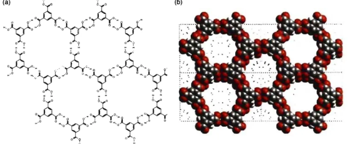
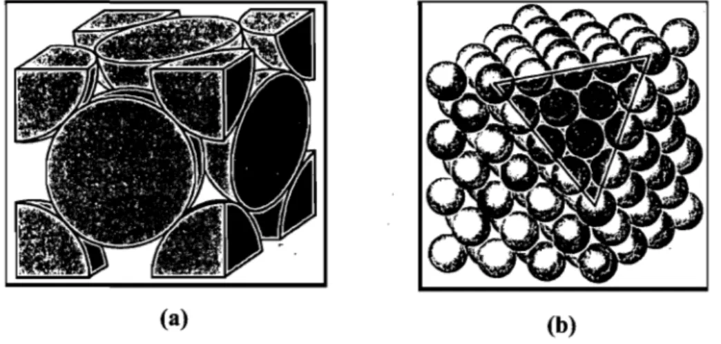
Schematic (a) and space-filling (b) views of the open-framed work phase of trimesic acid.
(a) STM image and (b) molecular model of a mono layer of
... 3
. ... 6
2,5-bis(dodecyloxy)terephthalic acid on graphite(Jsel = 1 nA, Vbias = ... 7
Figure 1.4 Figure 1.5 Figure 1.6 -0.6 V). Fundamental hydrogen bonding motifs ofDAT pairs. 1. Head-to-head. II. Head-to-side. III. Side-to-side. (a) Molecular structure of hexakis[ 4-(2,4-diamino-1 ,3,5-triazin-6-yl)phenyl]benzene (2). (b) Hexagonal sheets formed by hydrogen bonding ofDAT groups according to motif 1. STM images showing rosettes formed by adsorption of compound 3 on graphite. Insets show the propagation direction of rosette lattices (solid line) and the main symmetry axes of the graphite substrate (dashed line). (a) Monolayers of OPVT3 (compound 3, n = 3). (b) Monolayers of OPVT4 (compound 3, n = 4). The relative orientation of rows of rosettes with respect to the main crystallographic axes of graphite shows opposite 2D chirality (+ . ... 8
... 8
17.7 ± 1.70 and -2.3 ± 0.80 for OPVT3 and OPVT4, respectively). . ... 9
Figure 1.7 Figure 1.8 Figure 1.9 Tetrakis(3,5-dihydroxyphenyl)silane (4) crystallized from methyl propionate as a porous hydrogen-bonded network with submaximal interpenetration. STM image of a monolayer of tetradecanol (CI4H290H) adsorbed on graphite (Vbias = 1.127 V, lsel = 650 pA). High-resolution STM image of reticulated Fe-TDA open network with rectangular nanocavities on Cu(lOO) substrate. Figure 1.10 Self-assembly of a hypothetic diamondoid network by the association of a tetrahedral tecton directed by non-covalent interactions. Figure 1.11 (a) Molecular structure of tecton 5. (b) View (along c) of the crystal structure parallel to the channel axes, showing the cross sections of . ... 11
. ... 11
. ... 12
adjacent channe!s. Guest molecules of formic acid and dioxane are
omitted for clarity. . ... 16
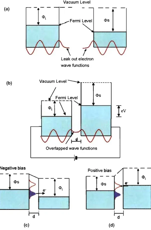
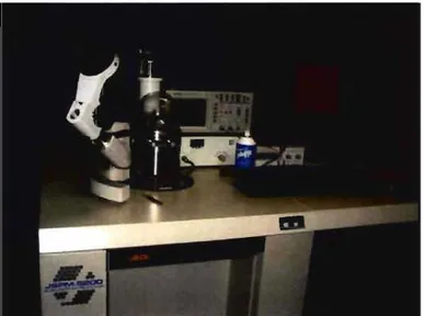
Figure 1.12 Schematic illustration of a hexagonal network buiIt from trime sic acid. Figure 1.13 Schematic illustration of the formation of ordered 2D networks by directed molecular se!f-assembly of a planar tecton with four sticky sites. (a) Trigonal network. (b) Hexagonal network. (c) Paralle! network. (d) Kagomé network. Figure 2.1 Figure 2.2 Figure 2.3 Figure 2.4 Figure 2.5 Figure 2.7 An STM image of a pattemed array of xenon atoms on Ni (lI 0). (a) Without bias applied, tip and sample have the same vacuum energy leve! but different Fermi levels. (b) When the distance, d, between tip and sample is close enough, and a small bias is applied, tunneling current flows across the vacuum gap. (c) When a negative bias is applied to the sample, tunneling current flows from sample to tip. (d) When a positive bias is applied to the sample, tunneling current flows from tip to sample. A schematic diagram ofSTM instrumentation. Two STM imaging modes. (a) Constant current mode. (b) Constant height mode. JSPM-5200 scanning-probe microscope. (a) STM image of the surface of flame-annealed Au. (b) 3D representation highlighting the reconstruction lines perpendicular to the . ... 17 ... 18 . ... 29 . ... 31 . ... 33 . ... 34 . ... 35 step edges. . ... 37 Figure 2.8 Figure 2.9 Figure 3.1 (a) Graphite layered structures. (b) Positional re!ationship between two identical graphene displays two different positions of carbon atoms A and B. . ... 39
(a) Typical STM image of the HOPG surface, with a mode! of the corresponding fragment of graphene superimposed. (b) High-resolution STM image of HOPG (l0 x 10 nm2). Vbias = -0.1 V, lset = 0.5 nA. STM images of 2D nanopattems created by adsorption of tecton DAT-l on HOPG (deposition from heptanoic acid, with Vbias = -1.5 V, Ise! = 100 pA). (a) Image showing well-ordered networks covering ... 40
large areas of surface in a single domain. (b) Higher-resolution image in which the tectons highlighted in blue and green have non-parallel or paralle1 orientations, respectively, relative to the underlying surface. The angle between the two types of tectons is
P
= ~ 40° .Figure 3.2 CPK models for the two proposed orientations oftecton DAT-l with respect to the underlying surface of HOPG. (a) View along c axis. (b) View along a axis.
Figure 3.3 Ca) Higher-resolution STM image of 2D nanopatterns created by depositing tecton DAT-l on HOPG (20 nm x 20 nm) in heptanoic acid. Molecules A (co-parallel orientation) and B (non-parallel orientation) are shown in green and blue, respectively. (b) Profile of molecule A, which shows higher tunneling CUITent (green curve), and the profile of molecule B, which shows lower tunneling CUITent
. ... 62 . ... 63 (blue curve). . ... 64 Figure 3.4 Figure 3.5 Figure 3.6 Figure 3.7 Figure 3.8
Proposed molecular model for the 2D coassembly of tecton DAT-I with heptanoic acid molecules mediated by hydrogen bonds (shown as broken lines).
Proposed 3D rnolecular model for surface nanopatterns formed by the adsorption oftecton DAT-l on HOPG. Two orientations, paralle1 and tilted, are shawn in green and blue, respectively. (a) View along the c axis, with possible hydrogen bonds between DAT groups shown as broken lines. The unit cell is highlighted in light blue. (b) Side view showing the 3D character of the proposed adsorption.
(a) ORTEP view of the structure of crystals of tecton DAT-l grown from CHChIDMSO, with the numbering scheme adopted. Ellipsoids are drawn at the 30% probability level. Hydrogen atoms are represented by spheres of arbitrary size. (b) Unit cell showing two conformers with different torsional angles (red and blue). Guest
. ... 68
. ... 69
molecules of DMSO are removed for c1arity. . ... 71
The structure of crystals of tecton DAT-l grown from CHChIDMSO, showing (a) 2D hydrogen-bonded sheets composed of a single conformer (red or blue) and (b) a central molecule (blue) forming hydrogen bonds with four neighboring molecules (light blue). Guest molecules of DMSO are omitted for c1arity. Hydrogen bonds are represented by broken lines.
STM topographs showing the patterns produced by depositing tecton DAT-2 on HOPG in heptanoic acid (Vbias = 1.5 V, ISel = 100
pA). (a) Well-ordered nanopattems over an area of 40 nm x 40 nm. (b) Enlarged image of the area highlighted in light blue, with superimposed space-filling models showing the head-to-head hydrogen bonding of DAT groups. The unit cell is highlighted in yellow. (c) Profile along the direction of the green line in (b), showing that the repeat distance is consistent with the molecular
length oftecton DAT-2. . ... 75
Figure 3.9 Proposed molecular model of tecton DAT-2 coadsorbed with heptanoic acid. The unit cell is highlighted in light blue. Figure 3.10 (a) ORTEP view of the structure of crystals of tecton DAT-2 grown from DMSO, with the numbering scheme adopted. Ellipsoids are drawn at the 50% probability level. Hydrogen atoms are represented by a sphere of arbitrary size. (b) View of the unit ceIl, with DMSO was removed for clarity. Figure 3.11 Structure of crystals of tecton DAT-2 grown from D"MSO. (a) View along the a axis showing the corrugated layers. (b) Within a single layer, no direct hydrogen bonds are found between neighboring tapes, which are associated with molecules of DMSO by hydrogen bonding. (c) View along the b axis showing neighboring molecules in six adjacent layers. Hydrogen bonds are represented by broken lines. Tectons are highlighted in red, blue, and yellow to show the relationship between views (a) and (c). Figure 3.12 STM image of 2D nanopattem created by depositing tecton DAT-3 on HOPG under the standard conditions (heptanoic acid, Vb;as = 1.5 . ... 76
. ... 77
. ... 78
V, Iset = 100 pA). . ... 80
Figure 3.13 (a) ORTEP view of the structure of crystals of tecton DAT-3 grown from CHChIDMSO, with the numbering scheme adopted. Ellipsoids are drawn at the 50% probability level, and hydrogen atomsare represented by a sphere of arbitrary size. (b) Unit cell with guest molecules of DMSO removed for clarity. (c) Single hydrogen bonds between the DAT groups of tectons in adjacent non-parallel tapes. . ... 83
Figure 3.14 Views of the structure of crystals of tecton DAT-3 grown from CHCh/DMSO Hydrogen bonds are represented by broken lines. (a) View along the c axis showing parallel hydrogen-bonded tapes cut by tapes lying at an angle. (b) Face-to-face hydrogen bonds with single tapes. . ... 84
Figure 3.15 Proposed molecular model for 2D nanopattems built from tecton
DAT-4. . ... 86
Figure 3.16 (a) ORTEP view of the structure of crystals of tecton DAT-4 grown from DMSO, with the numbering scheme adopted. Ellipsoids are drawn at the 50% probability level, and hydrogen atoms are represented by a sphere of arbitrary size. (b) Unit cell with gue st molecules of DMSO omitted for clarity. The two different conformers are highlighted in red and blue. Figure 3.17 Views of the structure of crystals of tecton DAT-4 grown from DMSO. Guest molecules of DMSO are removed for clarity. (a) View showing the stacking of sheets, with two adjacent layers highlighted in yellow and green. (b) View of a single sheet, with a rosette built from six tectons of altemating conformation highlighted in red and blue. Figure 3.18 Additional views of the structure of crystals of tecton DAT-4 grown from DMSO. Guest molecules ofDMSO are removed for clarity. (a) The characteristic embracing motif of hydrogen bonding between two conformers oftecton DAT-4 (shown in red and blue). Hydrogen bonds are represented by broken lines. (b) View along the a axis showing the cross section of channels. Figure 4.1 Figure 4.2 Figure 4.3 Figure 4.4 Views of the structure of crystals of benzene-3,3' ,5,5'-tetracarboxylic acid (BTA) grown from water. (a) View along the a axis showing a 2D hydrogen-bonded network. (b) View along the c axis showing interpenetrating corrugated sheets. STM images of 2D nanopattems created by the adsorption of tecton BTA on HOPG (deposition from heptanoic acid, with Vbias = 1.5 V, Ise! = 100 pA). (a) Image showing four domains, labeled A-D, covering an area of 100 nm x 100 nm. (b) Image showing an isolated domain within an area of 60 nm x 60 nm. Higher-resolution STM images of 2D nanopattems created by the adsorption of tecton BTA on HOPG showing open parallel networks (V bias = -1.5 V, JSel = 100 pA). (a) Image covering an area of 40 nm x 40 nm. (b) Image covering an area of 20 nm x 20 nm. (a) Higher-resolution STM topograph showing the well-ordered parallel structure produced by depositing tecton BTA on HOPG, with superimposed space-filling models (Vbias = -1.5 V, ISel = 100 pA). (b) Tentative molecular model of the paraUel structure with . ... 88 . ... 89 . ... 90 . ... 102 . ... .111 ... .112
Figure 4.5
Figure 4.6
Figure 4.7
unit cell highlighted in light blue.
STM images of 2D nanopatterns fonned by the adsorption of tecton
TA-6 on HOPG (deposition from heptanoic acid, with Vhias -1.5 V, lset 100 pA). (a) Larger image showing well-ordered networks
over an area of 40 nm x 40 nm. (b) Higher-resolution image showing bright protrusions which represent individual molecules. (a) Higher-resolution STM image showing the Kagomé network created by tecton T A-6. The unit celI is highlighted in light blue, the Kagomé network is shown in dark blue, and molecular models are superimposed as an aid to visualization. (b) Tentative molecular models showing a cyclic hydrogen-bonded hexamer oftecton TA-6.
The unit cell is highlighted in light blue. (c) An image of a Japanese Kagomé basket.
STM topograph of 2D nanopatterns fonned by depositing tecton
TA-5 on HOPG in heptanoic acid (Vbias = -1.5 V,lset 50 pA). The image shows a structure with local order but no large-scale periodicity. Two smalI areas ordered according to the paraUel network are highlighted in yelIow and Iight bIue, with blue arrows indicating the different directions of alignment. Another small area
.. ... 113
.. ... 116
. ... 117
ordered according to the Kagomé network is highlighted in green. .. ... 120
Figure 4.8 Figure 4.9 Ca) STM image of the assembly produced by the adsorption of tee ton TA-S., (b and c) Higher-resolution images of the areas in Figure 4.8a highlighted in green and blue, respectively, with superimposed models. These images show regions of local order according to the parallel network and the Kagomé network, as well as the smooth transition between them. STM images of 2D nanopatterns created by the adsorption of tecton TA-7 on HOPG (deposition from heptanoic acid, with Vhias -1.5 V, Iser = 50 pA). Ca) Image showing well-ordered monolayers with two domains. (b) Higher-resolution image showing a parallel network, with superimposed CPK models. The unit cell is highlighted in light . ... 121
blue. . ... 124
Figure 4.10 (a) STM image of a Kagomé network fonned by tecton TA-7, with superimposed space-filling models (heptanoic acid, V bias = -1.5 V, lset 50 pA). The unit cell is highlighted in Iight blue. .. ... 125
Figure 4.11 STM images showing 2D nanopatterns created by the adsorption of tecton TA-8 on HOPG (deposition from heptanoic acid, with Vbias ==
-1.5 V, Iset = 50 pA). (a) Image showing well-ordered networks over
an area of 80 nm x 80 nm. (b) Higher-resolution image with an ordered area highlighted in green.
Figure 4.12 Higher-resolution STM images of the 2D assembly of tecton TA-8
on HOPo. (a) Enlarged image of the area highlighted in green in Figure 4.11 b, with a unit cell highlighted in light blue. (b) Superimposed CPK models showing the hydrogen-bonded parallel network.
Figure 4.13 Schematic representation of molecular models.
Figure 4.14 STM images of the assemblies produced by the co-adsorption of mixtures oftectons TA-5 and TA-6 (deposition from heptanoic acid, with V bias = -1.5 V, Iset = 50 pA). (a) Co-adsorption ofa 1:1 mixture.
. ... 127
... 128 . ... 130
(b) Co-adsorption of a 1:4 mixture. . ... 133
Figure 4.15 STM images of 2D nanopatterns produced by the co-adsorption of mixtures oftectons TA-5 and TA-6 (deposition from heptanoic acid, with Vbias = -1.5 V, Iset = 50 pA). (a) Co-adsorption ofa 1:7 mixture.
(b) Co-adsorption of a 7: 1 mixture. . ... 134
Figure 5.1
Figure 5.2
Figure 5.3
Figure 5.4
STM images of 2D nanopatterns produced by the adsorption of tetraester TE-5 on HOPG (deposition from heptanoic acid, with Vbias = -1.5 V and lset = 100 pA). (a) Well-ordered nancipatterns over an area of 40 nrn x 40 nm. (b) Higher-resolution image with schematic representations of the butterfly structures highlighted in
blue and green (the short bars indicate individual molecules). The ... 146 unit cell is highlighted in black.
Proposed molecular models of the 2D network formed by the adsorption oftetraester TE-5 on HOPG a) C-H"'O hydrogen bonds are represented by broken lines. b) The unit cell is highlighted in
black. .. ... 147
(a) ORTEP view of the structure of crystals of tetraester TE-5
grown from hexane/CHCh, with the numbering scheme adopted. Ellipsoids are drawn at 50% probability level, and hydrogen atoms are represented by a sphere of arbitrary size. (b) Unit cell showing two parallel molecules.
Views of the structure of crystals of tetraester TE-5 grown from hexane/CHCh. (a) View showing the stacking of sheets, with two adjacent layers highlighted in green and yellow. (b) View of a single
Figure 5.5
sheet, showing that the molecules are parallei and closely packed. Close contacts are represented by broken lines.
STM images of 2D nanopatterns created by the adsorption of tetraester TE-6 on HOPG (deposition from heptanoic acid, with Vbias = -1.5 V and lset = 100 pA). (a) Well-ordered monolayers over
an area of 43 nm x 43 nm. (b) Schematic illustration showing the square network, with four adjacent individual molecules represented by green bars and surrounding molecules shown as black bars. The
. ... 151
unit cell is highlighted in blue. . ... 154
Figure 5.6
Figure 5.7
Proposed molecular models of the 2D network formed by tetraester
TE-6. a) A tentative model showing a square hydrogen-bonding motif involving aromatic C-H"'O interactions. b) The unit cell is highlighted in black. The molecules in blue and light blue represent two perpendicular orientations.
STM image of 2D nanopatterns formed by the adsorption of al: 1 (mol/mol) mixture of tecton TA-6 and tetraester TE-6 on HOPG (deposition from heptanoic acid, with Vbias = -1.5 V and lset = 50
. ... 155
pA). Five domains labelled 1 to V are highlighted in different colors. . ... 156
Figure 5.8
Figure 5.9
(a) ORTEP view of the structure of crystals of tetraester TE-6 grown from , hexane/CHCh, with the numbering scheme adopted. Ellipsoids are drawn at 50% probability level, and hydrogen atoms are represented by a sphere of arbitrary size. (b) Unit cell showing four parallel molecules.
Views of the structure of crystals of tetraester TE-6 grown from hexane/CHCh. (a) View along the a axis showing the stacking of sheets, with two adjacent layers highlighted in yellow and green. (b) View of a single sheet, with molecules parallei and closely packed. C-H"'O hydrogen bonds are represented by broken lines.
Figure 5.10 STM images of 2D nanopatterns formed by the adsorption of tetraester TE-9 on HOPG (deposition from heptanoic acid, with
Vbias = -1.5 V and lset = 50 pA). (a) A large-scale image showing poorly ordered nanopatterns. (b) An enlarged image of the blue are a
in Figure 6.10a, with the unit cell highlighted in green. The individual molecules are represented by blue bars.
Figure 5.11 Proposed molecular models for the 2D nanopatterns formed by the adsorption of tetraester TE-:-9. (a) The square network assembled by C-H-"O interactions, represented by broken lines. (b) The unit cell
. ... 157
. ... 158
is highlighted in light blue.
Figure 5.12 (a) ORTEP Vlew of the structure of crystals of tetraester TE-9 grown from hexane/CHCh, with the nurnbering scheme adopted. Ellipsoids are drawn at the 30% probability level. (b) Unit cell showing two conformers with different torsional angles (red and
. ... 162
blue). Guest molecules of CHCl3 are removed for clarity. .. ... 164
Figure 5.13 Structure of crystals of tetraester TE-9 grown from hexane/CHCh. (a) View along the a axis showing the crossed layers composed of a single conformer (red or blue). (b) View of the crystal structure showing cross-linked molecules. Guest molecules of chloroform are omitted for clarity.
Figure 5.14 View along the c axis showing interactions between neighboring conformers of tecton TE-9. Short contacts are represented by broken lines.
Figure 5.15 STM images of 2D nanopattems formed by the adsorption of tetraester TE-7 HOPG (deposition from heptanoic acid, with Vbias =
-l.5 V and Iset = 50 pA). (a) Large-scale image showing different domains. (b) Higher-resolution image showing inhomogeneous structures.
Figure 5.16 Enlarged STM images of2D nanopattems formed by the adsorption of tetraester TE-7 on HOPG. (a) Schematic representation of the square network, with green bars representing individual molecules. (b) Cavities in the square networks with different shapes and sizes
. ... 165
. ... 166
... 168
(highlighted in light blue). . ... 169
Figure 5.17 Proposed molecular models showing four possible hydrogen-bonded square networks formed by adsorbed tetraester TE-7, with cavities of different shapes and sizes highlighted in gray. C-H"'O hydrogen bonds are represented by broken lines.
Figure 5.18 Tentative molecular model showing a combination of four possible square networks formed by adsorbed tetraester TE-7, with cavities
. ... 170
highlighted in gray. . ... 171
Figure 5.19 STM images of 2D nanopatterns produced by the adsorption of tetraester TE-8 on HOPG (deposition from heptanoic acid, with
Vbias = -l.5 V and ISel = 50 pA). (a) Large-scale image (over an area
of 80 nm x 80 nm) showing six domains labeled A-F with diverse orientations relative to HOPG (shown with blue arrows). (b)
Higher-resolution image showing distinct linear chains.
Figure 5.20 STM images of 2D nanopattems formed by the adsorption of tetraester TE-8 on HOPG (deposition from heptanoic acid, with
Vbias = -1.5 V and lset = 100 pA). (a) Large-scale image showing two distinct domains (A and B). (b) Molecular structures of 2D enantiomers of tetraester TE-8 (A and ô). (c) (d) Enlarged STM images of domains A and B, respectively, with superimposed CPK models showing 2D chirality. The Unit cells are highlighted in blue and green.
Figure 5.21 (a) STM image of the 2D nanopattems produced by the adsorption of tetraester TE-8. The unit cell is highlighted in blue. (b) Profile of molecules aligned in a chain. (c) Proposed molecular model of hydrogen-bonded chains formed by tetraester TE-8. The unit cell is highlighted in blue. Hydrogen bonds are represented by broken lines.
Figure 5.22 (a) ORTEP view of the structure of crystals of tetraester TE-8
grown from hexane/CHCh, with the numbering scheme adopted. Ellipsoids are drawn at 30% probability level. Hydrogen atoms are represented by a sphere of arbitrary size. (b) View of the unit cell,
. ... 174
. ... 175 '
. ... 176
with CHCh removed for clarity. . ... 178
Figure 5.23 The structure of crystals of tetraester TE-8 grown from hexane/CHCh. (a) View of the crystal structure showing stacked sheets, with two adjacent layers highlighted in yellow and green. (b) View of the structure showing closely packed molecules within a sheet. Close contacts are represented by broken lines.
Figure 5.24 STM images showing the competitive adsorption of equimolar mixtures of tetraesters TE-6 and TE-8 (deposition from heptanoic acid, Vbias = -1.5 V and lset = 100 pA). Ordered phase 1 corresponds
to square networks built from compound TE-6, and phase Il corresponds to linear chains formed by compound TE-8.
Figure 5.25 STM images showing the competitive adsorption of equimolar mixtures of tetraesters TE-5 and TE-8 (deposition from heptanoic acid, Vbias = -1.5 V and lset = 100 pA). (a) Image over an area of 60
nm x 60 nm, with six domains labelled A-F, the boundary of domains highlighted in color, and non-specifie orientations indicated by blue arrow. (b) Large-scale image showing an area of
. ... 179
. ... 182
Figure 5.26 STM images showing the competitive adsorption of equimolar mixtures of TE-5 and TE-6 (deposition from heptanoic acid, Vbias =
-1.5 V and Iset = 100 pA). (a) Image of an area of 60 nm x 60 nm, showing multiple domains of square networks, labelled A-Ci; with the boundary of the domains highlighted in color. (b) Large-scale image of an area of 120 nm x 120 nm, showing well-ordered networks.
Figure 6.1
Figure 6.2
STM images of the 2D nanopattems formed by the adsorption of tetraester TE-IO on HOPG (deposition from heptanoic acid, with
Vbias -1.5 V and ISel = 100 pA). (a) Well-ordered monolayers
composed of multiple domains in non-specifie orientations with respect to the underlying graphite. (b) An enlarged image of the area highlighted in yellow in Figure 7.1a.
STM images of two homochiral domains formed by tetraester
TE-IO. Two types of bright spots are highlighted with blue and green arrows. (a) Square structures in clockwise orientation, with a schematic representation in light blue, and the unit celI highlighted in blue. (b) Square structures in a counter-clockwise direction, with a schematic representation in red, and the unit ceU highlighted in
.. ... 184 . ... 200 pink. . ... 201 Figure 6.3 Figure 6.4 Figure 6.5 Figure 6.6
Proposed molecular models of hydrogen-bonded square networks with 2D chirality produced by tetraester TE-IO. Hydrogen bonds are represented by broken lines. (a) Square structure arranged in clockwise orientation. (b)Square structure arranged in anticlockwise orientation.
Proposed 2D arrangement of tecton TE-IO adsorbed on graphite.
. ... 203
The unit cell is highlighted in light blue. . ... 204
(a) An STM image of 2D nanopatterns produced by depositing the tetramethyl analogue of tetraethyl ester TE-6 on HOPG under standard conditions (heptanoic acid, with Vbias = -1.5 V and Iset = 50
pA). (b) Proposed molecular mode! showing the hydrogen-bonded square structure, with four methyl groups accommodated in the
central cavity without filling it. ... 205
STM images of2D nanopattems on HOPG built frorn tecton TA-IO
by deposition from heptanoic acid (Vbias = -1.5 V and ISel = 100 pA).
(a) Two different phases A and B can merge fluidly into each other without any interruption. (b) Well-ordered patterns constructed from pairs of tectons that form regular zigzag rows. One such pair is
Figure 6.7
Figure 6.8
Figure 6.9
highlighted in green.
(a) An STM image with superimposed space-filling models showing the paraUel and racemic zigzag phases formed by tecton TA-IO. (b) Proposed molecular model showing hydrogen-bonded racemic dimers and their connections with neighbors. The unit ceU is highlighted in light blue.
STM images of 2D chiral nanopattems formed by the adsorption of tecton TA-IO on HOPG (deposition from heptanoic acid, with Vbias
= -1.5 V and Iset = 100 pA). (a) Image showing multiple domains. Area A (blue) consists of an essentiaUy homogeneous paraUel structure, whereas area B (yeUow) mixes the paraUel structure and zigzag structure. (b) Enlarged image of area A, with the unit ceU highlighted in blue. (c) Enlarged image of area B, with the unit ceU of the paraUel structure highlighted in green. Superimposed CPK models show the paraUel structure and racemic zigzag structure.
Proposed molecular models of the 2D chiral hydrogen-bonded paraUel structure produced by tecton TA-IO. Hydrogen bonds are represented by broken lines. The unit ceUs are highlighted in light blue and green, respectively.
Figure 6.10 STM images of 2D nanopattems formed by the adsorption of tetraester TE-ll on HOPG (deposition from heptanoic acid, with
Vbias = -1.5 V and Iset = 100 pA). (a, b) Large-scale ordered
monolayers over an area of 150 x 150 nm2. (c, d) Higher-resolution
images showing paraUel tapes.
Figure 6.11 Higher-resolution STM images of 2D chiral nanopattems formed by the adsorption of tetraester TE-ll as enantiopure tapes, with superimposed CPK models. The images show paraUel tapes aligned
in different orientations (represented by blue arrows).
Figure 6.12 STM images of 2D nanopattems created by the adsorption of tetraester TE-ll on HOPG. (a) Large-scale image showing two homochiral domains A and B, highlighted in blue and green, respectively. (b) (c) Enlarged images of are as A and B, respectively, with superimposed CPK models. The unit ceUs are highlighted in blue and green. The white arrows in each image represent different orientations of the long molecular axis.
Figure 6.13 (a) Proposed molecular models ofhydrogen-bonded tapes composed of opposite" 2D enantiomers of tetraester TE-Il. Hydrogen bonds
. ... 209 . ... 210 . ... .211 . ... 212 . ... 216 . ... 217 . ... 218
are represented by broken lines. (b) Proposed 2D arrangement of
one enantiomer of TE-Il. The unit cell is highlighted in light blue. . ... 219
Figure 6.14 STM images of2D nanopatterns formed by the adsorption oftecton
TA-11 on HOPG (deposition from heptanoic acid, with Vbias = -1.5
V and Ise! 100 pA). (a) Large-scale image showing ordered arrays with areas of defects. (b) Higher-resolution image showing well-ordered patterns highlighted in red. A small domain showing a different orientation is highlighted in blue.
Figure 6.15 (a, b) Enlarged STM images of 2D enantiomorphous domains with superimposed moiecular modeIs, showing a rhombic structure formed by !ceton TA-11. The unit ceUs are highlighted in red and bIue, respectively. (c, d) Proposed molecular models suggest the formation of linear tapes composed of single 2D enantiomers of tecton TA-Il. Hydrogen bonds are represented by broken lines. The
. ... 222
unit ceUs are highlighted in pink and light blue,respectively. . ... 223
Figure 6.16 An optimized molecular model for 2D arrangement of tecton TA-11. Hydrogen bonds arc represented by broken lines. The unit
Scheme3.1 Scheme3.2 Scheme3.3 Scheme3.4 Scheme3.5 Scheme3.6 Scheme4.1 Scheme4.2 Scheme4.3 Scheme4.4 Scheme4.5 Scheme5.1 Scheme 5.2 Scheme 6.1 Scheme 6.2 Scheme 6.3 Scheme 6.4 Scheme 6.5 Scheme 6.6 Scheme6.7
Table of Schemes
Molecular structures oftectons DAT-I, DAT-2, DAT-3, and DAT-4 ... 55 Synthesis of compound DAT-l ... 57 Synthesis of compound DAT-2 ... 58 Synthesis of compound DAT-3 ... 59 Synthesis of compound DAT-4 ... 60 Molecular models showing potential intermolecular hydrogen bonding in 2D
nanopattems formed by tecton DAT-I on HOPG. ... 66 Molecular structure oftectons TA-5, TA-6, TA-7, and TA-8 ... 1 03 Synthesis of tecton TA-5 ... 1 05
Synthesis of tecton T A-6 ... 106 Synthesis oftecton TA-7 ... 107 Synthesis oftecton TA-8 ... 109 Molecular structures oftetraesters TE-5, TE-6, TE-7, TE-8, and TE-9 ... 142 Synthesis of tetraester TE-9 ... 144 Chemical structures ofcompounds TE-lO, TA-IO, TE-lI, and TA-lI ... 194 Synthesis of compounds TE-IO and TA-IO ... 196 Synthesis oftectons TE-lI and TA-lI ... 197 2D enantiomers of tetraester TE-IO ... 199 2D enantiomers of tecton TA-lO ... 207 Proposed 2D enantiomers of tetraester TE-lI, with an arbitrary conformation of the carboethoxy groups similar to the one favored by isomer TE-8 ... 215 2D enantiomers oftecton TA-lI ... 221
Table 4.1
Table 4.2
Index of Tables
2D networks formed by tectons constructed by coupling two isophthalic acid units directly (DTA) or by connecting them to linear spacers, including ethyne (TA-5), 1,4-diethynylbenzene (TA-6), 1,4-diethynylnaphthalene (TA-7), and 9,10-diethynylanthracene (TA-8).
Calculated gas-phase stabilization energies (kcallmol) per hydrogen bond for trimeric, tetrameric, and hexameric aggregates of tectons
. ... 129
A
BTA CPK DAT DFT DMF 2D 3D DMSO HOMO HOPG HRMS IR LUMO mL mg mmol rnIz mpList of Abbreviations
Angstrom 3,3' ,5,5' -biphenyltetracarboxylic acidmolecular models by Corey, Pauling, and Koltun degree Celsius
4,6-diamino-l,3,5-triazinyl density functional theory
N, N-dimethylformamide two dimensional
three dimensional dimethyl sulfoxide
highest-occupied molecular orbital highly-oriented pyrolytic graphite high-resolution mass spectrum infrared
lowest-unoccupied molecular orbital millilitre
milligram millimole
mass per unit charge melting point
MS nm nA NMR OPE ORTEP pA ppm SEM STM TEM TRF TMA TMS URY Y mass spectrometry nanometer nanoampere
nuclear magnetic resonance o ligo(pheny leneethyny lene)
Oak Ridge Thermal-Ellipsoid Plot Program plcoampere
parts per million
scanning electronic microscopy scanning tunneling microscopy transmission electron microscopy tetrahydrofuran
benzene-l ,3,5-tricarboxylic acid trimethy lsily 1
ultra-high vacuum volt
chemical shi ft in ppm relative to Me4Si in NMR spectra
CHAPTER 1
1.1
Supramolecular Chemistry and Self-Assembly
Beyond molecular chemistry, which is based on covalent bonds, lies the field of supramolecular chemistry, which studies how molecules can assemble into multi-molecular complexes held together by noncovalent interactions, such as hydrogen bonding, metal coordination, 7t-7t stacking, hydrophobic effects, and van der Waals forceS.I.5 In biological
systems, for example, combinations of multiple noncovalent interactions have provided excellent control of key interactions, su ch as protein-ligand and protein-protein association, for the assembly of proteins into functional complexes. Over the la st 30 years, supramolecular chemistry has grown into a major field of investigation. A number of well-designed structural and functional building blocks, inc1uding cyc1odextrins,6'9 cucurbiturils,IO·12 crown ethers,13-15 and porphyrins/ 6-19 have been employed in the construction of large new architectures. Furthermore, with the emergence and flowering of nanotechnology, novel building blocks su ch as fullerenes,2o-24 nanopartic1es,25-28 and dendrimers29-32 are now being readily used to build supramolecular architectures with fascinating properties in the area of molecular electronics, optics, magnetics, and sensing.
Molecular self-assembly is a key concept of supramolecular chemistry, wherein the association of molecules is directed by noncovalent interactions, without guidance or management from external sources. The process is essential and well-established III
biological systems, such as in the association of lipids to form self-assembled membranes, the formation of double helical DNA linked by hydrogen bonding of the individual strands, and the association of proteins to produce complex aggregates.
"r
""'~
-
'"
..
,,~~ VI< 'i" •. '-.;: ~?: ",~K
~.,~J
. ~: i~(. ~~ 0; -j. _ ~, /~ 1Figure 1.1 Hexameric hydrogen-bonded capsules built from molecule 1.34
Currently, self-assembly plays an important role not only in the supramolecular systems
of nature, but also in new bottom-up approaches to artificial nanoscale objects for use in
nanotechnology.33 Unlike making new molecules via complex chemical reactions, the process of self-assembly allows large architectures to be readily made by the spontaneous association of small molecules requiring fewer steps to synthesize. Noncovalent interactions are known to be far weaker than covalent bonds; however, multiple noncovalent interactions, such as multiple hydrogen bonds, can produce remarkably stable structures. As shown in Figure 1.1, C-hexylpyrogallo[4]arene (1) is a typical example
which can form hexameric hydrogen-bonded capsules that enclose 1200 to 1500
A
3 ofspace.34-36 These capsules are stable in solution in polar and nonpolar sol vents and can host
1.2
Crystal Engineering and Surface Nanopatterning
Molecular crystal engineering is a subdivision of supramolecular chemistry that aims at the design and synthesis of periodic molecular structures with desired properties, based on the understanding and exploitation of intermolecular interactions. The two main strategies currently in use for positioning molecules in crystal engineering are based on hydrogen bonding and coodination to metals. During the past decades, the control of crystallization in three dimensions (3D) by using molecular self-assembly directed by noncovalent interactions has been extensively studied with the aid of X-ray crystallography.40-45 In princip le, it is also possible to envisage the control of molecular organization in 2D by using analogous strategies to position the molecular components. This possibility links the fields of crystal engineering and surface science. Unlike 3D crystal engineering, which has been explored for decades, 2D crystal engineering involving supramolecular nanopatteming at liquid-solid interfaces or under ultra-high vacuum (URV) is a new area of research with opportunities that have not yet been fully exploited. The field has begun to attract great interest, particularly since the invention of scanning tunnelling microscopy (STM).46-5o In the study summarized in this thesis, we have blended 3D and 2D crystal engineering. In particular, we have focused on the use ofhydrogen bonding to direct crystallization in 2D to nanopattem surfaces, and we have increased our understanding by carrying our related studies of 3D crystallization as weIl.
1.2.1
Hydrogen Bonding
Hydrogen bonding is defined as a special type of dipole-dipole force that exists between an electronegative atom and a hydrogen atom bonded to another electronegative atom.51-53 The classical type ofhydrogen bond can be represented as D-H"'A, where D is
considered the hydrogen-bond donor and A the acceptor. Both D and A are electronegative atoms, su ch as 0, N, F, S, C, Cl, and Br. The strength of a hydrogen bond varies from very weak (l ~2 kJ/mol) to extremely strong (> 155 kJ/mol), depending on the identity of D and A. For example, the F-H"'F hydrogen bond has a strength of 155 kJ/mol, but the N-H,,·O hydrogen bond has a strength of only 8 kJ/mol.
In addition to classical hydrogen bonds, such as O-H"'O, related interactions exist in which C-H bonds can be considered to act as hydrogen-bond donors.54 Su ch interactions
are normally weaker than conventional hydrogen bonds, but they are thought to be crucial in molecular complexes and crystal structures. Other types of hydrogen bonds involving aromatic rings or triple bonds, such as O-H,,·7t, N-H-,,7t, C-H,,·7t, are also of great interest. 55-56
Hydrogen bonds are the most commonly used noncovalent interactions to build either 3D or 2D crystal structures by design, largely because they have an attractive combination of properties, including high directionality, mode st strength, and reversible formation. As a result, supramolecular assemblies directed by hydrogen bonding can be entirely or partially predicted, and they usually have strong collective stability. A number of hydrogen bonding motifs have been well-studied and applied extensively to the construction of
supramolecular architectures.57-61 In particular, carboxyl (-COOH), diaminotriazine (DAT),
and hydroxyl (-OH) are functional groups widely used to generate predictable hydrogen bonds, as will be discussed in detail below.
1.2.1.1
Carboxyl Groups
Carboxyl groups (-COOH) are widely used in crystal engmeenng because they
self-associate reliably to form cyclic hydrogen-bonded dimers.62 As shown in Figure 1.2,
1,3,5-benzenetricarboxylic acid (trimesic acid, or TMA) is a typical example. Self-association of ail carboxyl groups according to the normal motif yields 2D hexagonal sheets, which
then interpenetrate to generate the 3D crystal. 63 STM investigations have revealed that
the 2D crystallization of trimesic acid at the liquid-solid interface of heptanoic acid and graphite occurs in an analogous way, and the 2D arrangement is consistent with the structure
found in 3D.64 In addition, derivatives of isophthalic and terephthalic acids, which have the
same benzene core but only two carboxyl groups, behave similarly, and they have been
'·)..oÀ··oX(··
-,oYo-'
~oyo~ ~oyo0'1' 09 ° 9
(b)
... .. ... .. .. ..
oA." .
_,0
°~
.Iyy(
.
..
_~
x,._ ."
~ lyyt ",0
oA
•
o
~ ~
," .
cyo
0):'0
0):'
,À,.
.,À,.
o.,À
,0 o~o o~.o °"
"'0
X
0-'
-'0):'
0-o 9 () ?-
-Figure 1.2 Schematic (a) and space-filling (b) views of the open-framework phase of trimesic acid.63
used as building blocks to produce well-ordered 2D networks on graphite surfaces (Figure 1.3).46
Figure 1.3 (a) STM image and (b) molecular model of a monolayer of 2,5-bis(dodecyloxy) terephthalic acid on graphite (lse, = 1 nA, Vbias = -0.6 V).46
1.2.1.2
Diaminotriazine Groups
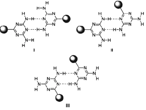
4,6-Diamino-l,3,5-triazinyl (DAT) groups can be used to generate a variety of hydrogen-bonding motifs because they incorporate multiple sites that act as hydrogen-bond donors and acceptors. As depicted in Figure 1.4, hydrogen-bonded pairs can be formed in three different modes, which have been called face-to-face, face-to-side, and side-to-side, respectively.65 Because of this complexity, supramolecular assemblies directed by DAT groups are not entirely predictable; however, they can still be confidently predicted to obey one of the three fundamental hydrogen-bonding patterns shown in Figure 1.4, particularly in their 3D structures.65.71
H
H, ,\-N ,H
H-N H ~ 'N-H----N1>--0
N=<H
o-{
N- -- -H-N N-4'H
N-H· - - -N }---N N=<FN
H
~-4'N----H-N'H
N-H
1N-H
1 H H Il H~N
H 'N-H----N')-N
H, N-i )=N 'H N...II N- -. -H-N 1 \=\
'
H N-Q
H IIIFigure 1.4 Fundamental hydrogen-bonding motifs of DAT pairs. 1. Face-to-face. II. Face-to-side. III. Side-to-side.65
2
(a) (b)
Figure 1.5 (a) Molecular structure ofhexakis[ 4-(2,4-diamino-1 ,3,5-triazin-6-yl) phenyl]benzene (2). (b) Hexagonal sheets formed by hydrogen bonding of DAT groups according to motif 1. 71
;(0
3
Figure 1.6 STM images showing rosettes fonned by adsorption of compound 3 on graphite. Insets show the propagation direction of rosette lattices (solid line) and the main symmetry axes of the graphite substrate (dashed line). (a) Monolayers of OPVT3 (compound 3, n = 3). (b) Monolayers of OPVT4 (compound 3, n = 4). The relative orientation of rows of rosettes with
respect to the main crystallographic axes of graphite shows opposite 2D chirality (+ 17.7 ± 1.70
and -2.3 ± 0.80 for OPVT3 and OPVT4, respectively).74
great interest in engineering hydrogen-bonded supramolecular architectures. The Wuest group has developed a number ofmolecules with well-designed crystal structures based on the application ofthis functional group.65-71 Recently, hexakis[4-(2,4-diamino-I,3,5-triazin-6-yl)phenyl]benzene (2), which incorporates a disc-shaped hexaphenylbenzene core and sixperipheral DAT groups, was shown to crystallize to give non-interpenetrated 3D networks built from hexagonal sheets (Figure 1.5).71 Each molecule associates with six
neighbors by forrning typical hydrogen-bonded DAT pairs according to the face-to-face motif. Although DAT groups have been widely used to build up 3D crystals, only a few examples of their use in 2D surface nanopatterning have been reported.72-75 For example, melamine
(l,3,5-triazine-2,4,6-triamine) was coadsorbed with perylenetetracarboxylic diimide to forrn heteromolecular hydrogen-bonded networks on silver surfaces.72,73 De Fey ter and co-workers have investigated oligo(p-phenylenevinylene) diaminotriazine (OPVT) derivatives (3), which generate homochiral rosette structures on graphite surfaces directed by se1f-complementary hydrogen bonds between adjacent triazÏne moieties (Figure 1.6).74
1.2.1.3
Hydroxyl Groups
Hydroxyl groups might appear to be able to generate straightforward patterns of hydrogen bonding. However, molecules grafted with multiple hydroxyl groups can produce extremely complex hydrogen-bonded networks. 34 ,76-78 For example, tetrakis(3,5-dihydroxyphenyl)silane (4) was found to crystallize as a porous hydrogen-bonded network with submaximal interpenetration and nov el bicontinuous systems of channels (Figure 1.7).78 The central molecule (red) interacts with 14 neighbors via a complex array of 20 hydrogen bonds and aryl-aryl interactions. In 2D crystallization, hydroxyl groups can also play a key role in producing supramolecular networks. Many alkanols, su ch as 1-tetradecanol, 1-dodecanol, 1-decanol, 1, 12-dodecanediol, and 1,14-tetradecanediol, have been found to forrn lamellae of herringbone structures when deposited on graphite (Figure 1.8). This observation is consistent with the hypothesis that adsorption is driven in
HO~OH HO \
Y /_
OHP:Si~
HOn
OH HO ~ OH 4Figure 1.7 Tetrakis(3,5-dihydroxyphenyl)silane (4) crystallized from me th yI propionate as a
porous hydrogen-bonded network with submaximal interpenetration.78
Figure 1.8 STM image of a monolayer of l-tetradecanol (C'4H290H) adsorbed on graphite (Vbias
part by close packing of extended alkyl chains to fonn characteristic tapes, and hydrogen
bonding of hydroxyl headgroups then detennines the interaction of the tapes and their
detailed angular geometries.79
1.2.2
Metal Coordination
Besides hydrogen bonding, metal coordination is a powerful strategy for building
supramolecular architectures, and this strategy has been widely used in recent years. A
variety of metals can be coordinated to organic ligands, such as alkali metals, alkaline earth
metals, transition metals, lanthanides, and actinides. Many supramolecular metal-organic
coordination assemblies have been constructed, including metal-containing cages,
macrocyles, interlocked species (such as catenanes and rotaxanes), and helicates.8o-85
Figure 1.9 High-resolution STM image of reticulated Fe-TDA open network with rectangular nanocavities on Cu( 1 00) substrate.86
In surface nanopatteming, metal-ligand coordination offers a new way to build open
networks with rectangular nanocavities formed by 4,1',4',1" -terphenyl-I,4" -dicarboxylic acid (TDA) coordinated with Fe on a Cu(lOO) surface.86
1.2.3
Van
der Waals Interactions
Van der Waals interactions are a sum of long-range inductive and dispersive intermolecular forces.91 Classic inductive forces include permanent dipole-dipole and induced dipole-dipole interactions. Such interactions have a magnitude that varies as the separation of the interacting species. Dispersion forces are quantum mechanical in nature and result from momentary fluctuations of the electron density within molecules. Van der Waals forces are relatively weak compared with normal chemical bonds, but their collective effects are not negligible, thus leading to a fundamental role in many fields, such as supramolecular chemistry and surface science. A number of well-designed molecules with long akyl chains have been found to self-assemble into highly-ordered patterns at surfaces by van der Waals interactions among molecules, as weIl as between adsorbed molecules and substrates.46
,47
1.3
Molecular Tectonics
Molecular tectonics pro vides a powerful strategy for engineering three dimensional (3D) crystal structures, based on molecular self-assembly of building subunits which have been called tectons. Tecton is the Greek word for builder, and it describes any molecule