HAL Id: pastel-00973376
https://pastel.archives-ouvertes.fr/pastel-00973376
Submitted on 4 Apr 2014HAL is a multi-disciplinary open access
archive for the deposit and dissemination of sci-entific research documents, whether they are pub-lished or not. The documents may come from teaching and research institutions in France or abroad, or from public or private research centers.
L’archive ouverte pluridisciplinaire HAL, est destinée au dépôt et à la diffusion de documents scientifiques de niveau recherche, publiés ou non, émanant des établissements d’enseignement et de recherche français ou étrangers, des laboratoires publics ou privés.
Delphine Reche
To cite this version:
Delphine Reche. Relations between microstructure and bendability on TRIP-aided steels for automo-tive products. Engineering Sciences [physics]. École Nationale Supérieure des Mines de Paris, 2011. English. �NNT : 2011ENMP0016�. �pastel-00973376�
MINES ParisTech
École doctorale n° 432 : Science des Métiers de l’Ingénieur
Delphine RECHE
Le 18 mars 2011
Relations entre microstructure et aptitude au pliage des aciers à
effet TRIP pour application automobile
Relations between microstructure and bendability on TRIP-aided
steels for automotive products
Thèse confidentielle jusqu’au 31 janvier 2014
Doctorat ParisTech
T H È S E
pour obtenir le grade de docteur délivré par
l’École nationale supérieure des mines de Paris
Spécialité “ Sciences et Génie des Matériaux ”
présentée et soutenue publiquement parDirecteur de thèse : Anne-Françoise GOURGUES-LORENZON Co-encadrement de la thèse : Thierry STUREL
T
H
È
S
E
JuryMme Sandrine THUILLIER, Professeur, Université de Bretagne Sud Président
M. Michel BRUNET, Professeur, INSA Lyon Rapporteur
M. Paul VAN HOUTTE, Professeur, Katholieke Universiteit Leuven, Belgique Rapporteur
Mme Véronique AUBIN, Professeur, Ecole Centrale Examinateur
Mme Anne-Françoise GOURGUES-LORENZON, Professeur, Mines Paris Tech Examinateur
M. Thierry STUREL, Ingénieur de recherche, ArcelorMittal Global R&D Examinateur
M. Jacques BESSON, Directeur de recherche CNRS, Mines Paris Tech Examinateur
Relations between microstructure and bendability on
TRIP-aided steels for automotive products
Abstract
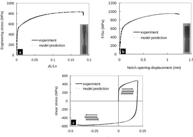
In order to limit fuel consumption, automotive industries push the steelmakers to develop thinner sheets with higher strength. Ultra High Strength Steels (UHSS) such as low alloy TRIP (TRansformation Induced Plasticity)-aided steels enable to get complex shapes for automotive parts. However, understanding the formability of these steels appears to be complex and involves a detailed study of failure mechanisms during forming tests. Therefore, links between microstructural features, in particularly banded structures, and formability were investigated in order to better predict the bending ability of steels as a function of their microstructure. In this study, four low alloy TRIP-aided steels exhibiting different bending performances were characterized using both air and stretch bending tests. From scanning electron and light microscopy observations, cracks initiate from the outer surface or from just below in air-bending, but from the central segregation bands in stretch bending. Fracture surfaces after bending tests are ductile and damage mainly appears by ferrite/martensite interface decohesion and occasionally as microcracks within martensite islands. An original procedure based on thickness-reduced specimens, with various locations of the main hard band within the specimen thickness, was set up. It enabled to propose a relationship between cracking, local thickness of hard band and local strain during air-bending. In order to develop a local fracture criterion that could be used for any bending test, stress and strain fields were computed by numerical simulation of the two bending tests. For that purpose, an experimental database including tensile tests on smooth and notched samples as well as shear tests was established. Material parameters of constitutive equations, accounting for anisotropic elasto-plastic behaviour with mixed hardening, were determined from this database. Finite element simulation of both bending tests associated with a ductile damage criterion made it possible to satisfactorily predict strain fields, bending load-displacement curves and fracture angle. The possibility of using simplifying assumptions in the model (such as an isotropic flow criterion, pure isotropic hardening, two-dimensional assumptions and simplified boundary conditions) is also discussed.
Keywords: Ultra High Strength Steels, TRIP-aided steels, microstructure, damage
Relation entre microstructure et aptitude au pliage des
aciers à effet TRIP pour application automobile
Résumé
Pour limiter la consommation des véhicules, les industries automobiles demandent aux aciéristes de développer des aciers de plus en plus fins avec des hautes résistances. Les aciers très haute résistance (THR) comme les aciers TRIP (TRansformation Induced Plasticity) permettent d’effectuer des pièces automobiles aux formes complexes. Néanmoins, le compréhension des mécanismes de mise en forme de ces aciers n’est pas simple et implique une étude détaillée des mécanismes de rupture apparaissant durant la mise en forme. Ainsi, les liens entre les paramètres microstructuraux, en particulier les structures en bandes, et la mise en forme ont été étudiés pour obtenir une meilleure prédiction de la capacité en pliage des aciers en fonction de leur microstructure. Dans cette étude, quatre aciers TRIP présentant des performances en pliage différentes ont été caractérisés à la fois en pliage en V et en pliage sous traction. A partir d’observations au microscope optique et à balayage, nous avons démontré que les fissures s’initiaient à partir de la surface ou juste en dessous en pliage en V alors qu’elles s’initiaient au niveau de la ségrégation centrale en pliage sous traction. Les surfaces de rupture après pliage sont ductiles et l’endommagement apparait principalement par décohésion de l’interface ferrite/martensite et occasionnellement par rupture des ilots martensitiques. Une procédure originale basée sur des échantillons rectifiés présentant la bande de ségrégation à différents endroits dans l’épaisseur a été établi. Ce travail a permis de proposer une relation entre l’épaisseur d’une bande, son endommagement et sa déformation locale atteinte pendant un test de pliage en V. Pour développer un critère de rupture pour ces tests de pliage, les champs de contrainte et déformation ont été calculés par simulation numérique pour ces deux tests. Pour ce faire, une base de données expérimentale incluant des tests de traction sur éprouvettes lisses et entaillées et des tests de cisaillement a été établie. La loi de comportement du matériau a été déterminée à partir de cette base expérimentale et présente un comportement élasto-plastique anisotrope avec écrouissage mixte. La simulation numérique des deux essais de pliage associée à un critère d’endommagement a permis de prédire de manière satisfaisante les champs de déformation, les courbes force/déplacement ainsi les angles de rupture. La possibilité d’utiliser des modèles simplifiés (tels qu’un critère d’écoulement isotrope, un écrouissage purement isotrope, des calculs en 2D et des conditions aux limites simplifiées) a également été discuté.
Mots clés: Aciers Très Haute Résistance, aciers TRIP, microstructure, mécanismes
d’endommagement, test de pliage en V, test de pliage sous traction, simulation numérique par éléments-finis.
Au terme des ces trois années de thèse, le temps est venu de présenter mes remerciements à toutes les personnes qui ont contribué à cette aventure scientifique et humaine. Sans leur aide efficace et leur soutien précieux, ce manuscrit n’aurait pas abouti à ce qu’il est aujourd’hui.
Je remercie vivement tous les membres de mon jury pour le temps consacré à la lecture de mon manuscrit et pour leurs précieux conseils. Un grand merci à Paul Van Houtte et Michel Brunet qui ont accepté d’être rapporteurs de ces travaux ainsi qu’à Sandrine Thuillier et Véronique Aubin, les examinatrices de mon jury. Leurs remarques pertinentes m’ont permis d’améliorer la qualité de ce travail.
Cette thèse a été menée en collaboration avec le Centre des Matériaux (CdM) de l’Ecole des Mines de Paris et ArcelorMittal Global R&D. Ainsi, je tiens ainsi à remercier Esteban Busso, directeur du CdM, de m’avoir accueillie dans cet environnement technique et humain de qualité. Je remercie également Michel Babbit de m’avoir reçue au Centre Auto ainsi que Messieurs Alain Carmet, Philippe Hein et Martin Munier qui m’ont permis d’évoluer et de m’intégrer très rapidement au sein des équipes "MBIWS" puis "AUP²". Pour reprendre un ordre plus chronologique, je suis très reconnaissante à Isabelle Boul d’avoir lancé cette thèse à la suite de mon stage de fin d’études, de m’avoir fait confiance et de m’avoir donné le goût de la recherche et plus particulièrement celui de la mise en forme.
Je tiens maintenant à remercier sincèrement Anne-Françoise Gourgues-Lorenzon qui a dirigé cette thèse et m’a si bien accompagnée durant ces trois années. Un grand merci pour ta disponibilité, ton écoute et implication malgré la distance, la rigueur et les méthodes de travail que tu m’as apportées mais aussi pour toutes ces relectures méticuleuse d’articles ou de chapitres en temps imposé.
Je remercie mon encadrant chez ArcelorMittal, Thierry Sturel, de m’avoir accompagnée pendant cette thèse. Merci pour ta confiance et ton soutien au cours de cette aventure. Je te remercie également pour ta disponibilité, tes conseils et l’autonomie que tu m’as laissée tout au long de cette thèse.
Un grand merci également à Jacques Besson. Vous avez hérité d’une énième thésarde alors que vous en aviez déjà beaucoup mais grâce à vous, j’ai pu découvrir les terres inconnues de la simulation numérique. Avant cette thèse, je n’avais jamais utilisé les éléments finis, alors merci pour votre patience, pour les explications sur ces modèles complexes et pour toutes les réponses aux problèmes que j’ai pu rencontrer sur ZéBuLon.
Ayant passé un an au Centre des matériaux et deux chez ArcelorMittal, je vais d’abord remercier mes collègues d’Evry puis ceux de Maizières, en espérant n’oublier personnes (si c’est le cas, je leur présente par avance mes excuses).
Je souhaiterai tout d’abord remercier les chercheurs et techniciens qui m’ont aidé au cours de cette thèse. Merci à toutes les personnes de l’atelier, Christophe, Jean-Pierre, René, Georges, Michel pour l’usinage des éprouvettes ainsi que pour celui du montage du pliage
service administratif. Merci Daniel pour les essais de RX. Merci Anne et Maria de m’avoir initiée au MEB et un grand merci également à Nicole pour les manips de nanoindentations qui étaient loin d’être une partie de plaisir…Merci également à Abdennour de m’avoir aidée à dessiner sous Inventor mais aussi de m’avoir formée à l’utilisation des différentes machines du bocal. Merci également à M. Pineau pour les discussions sur des problèmes métallurgiques ou autres.
Cette aventure aurait sans doute été moins agréable sans la présence de l’ensemble des thésards et autres personnes du CdM qui m’ont accueillie au cours de cette année à Evry et où entraide et bonne humeur ont permis un travail efficace. Merci Djamel pour tous les renseignements sur la mécanique, sur Linux ou encore sur Zébulon.
Pika…que dire de la morphomath, merci d’avoir été présent à chaque moment, pour ton écoute, ton soutien, tes conseils, et pour tout le reste. Merci également pour le roller dans les rues parisiennes...
Clémence, ma grande amie, sans toi, Evry n’aurait surement pas été pareil. Merci pour tout ce que tu as fait pour moi, pour ton écoute, tes encouragements. Merci également pour le prêt de ton clic-clac car sans toi mes aller-retour à Evry n’auraient sans doute pas été aussi sympa.
Florence, merci également pour ton écoute et tes encouragements surtout en fin de thèse. Je te souhaite bon courage pour la suite dans ton nouveau travail et félicitation à la première "Docteur" de notre promo.
Angel, merci de m’avoir fait découvrir "le pantalon" et merci pour l’hébergement après les thèses sur Paris. Bonne continuation.
Julie, merci de m’avoir initié à Zébulon et m’avoir appris à jouer avec les lignes de codes car au début ce n’était vraiment pas simple. Bon courage pour la suite et j’espère que tu es venue à bout de ces fameux aciers TWIP.
Je vais maintenant remercier tous les autres thésards ou autres personnes avec qui j’ai pu partager du travail, des rires, des sorties, etc…merci Yohann pour ta terrasse, merci Julien d’avoir été présent pendant cette année et d’avoir fait le petit bout de chemin entre le CdM et le 407. Un grand merci également à Tony, Guillaume, Thomas, Cédric, Bahram, Sophie, Vlad, Guilhem, la grande Julie, Jianqiang, Nikolai, Fabrice, Steeve, Clara, Laurent, Florine, Greg, Aurélie, Thomas….à qui je souhaite une grande réussite.
Je souhaiterais maintenant remercier mes collègues d’ArcelorMittal. Je vais tout d’abord remercier les ingénieurs et techniciens qui m’ont formée et aidée pour les différents essais que j’ai eu à effectuer…parmi eux, Grégory pour les essais de RX, Aurélien pour les manips de sigmamétrie, Stéphane pour les manips avec le logiciel Aramis et Nathalie et Rémi pour les observations métallographiques de la fin de thèse. Je souhaiterai également remercier tout le service métallo de m’avoir formée, aidée et conseillée quand j’avais des problèmes d’attaques ou d’observations. Merci également à toutes les personnes d’AUP² avec qui j’ai pu travailler et en particulier le service mise en forme.
Merci à Germain, Max et Flo (mon parrain) de m’avoir appris différents tests de mise en forme et de m’avoir accueillie dans votre bureau. Merci également à Nico, Rémi, Cyril, Benoît et Dominique pour l’aide et les conseils que vous m’avez apportés. Xavier, je te remercie également pour tes conseils sur la simulation numérique et ton aide sur des problèmes pas toujours simples à résoudre.
Merci également à toutes les autres personnes des deux autres services (soudage et fatigue) pour votre soutien et encouragements tout au long de cette thèse…Bastien, Michel, Rémi
également pour cette dernière année de thèse), etc. Je remercie aussi Rachel et Danielle, les secrétaires de mon service ainsi que Sabine Fogel pour les recherches bibliographiques. Merci beaucoup Jonas, Pape et Perrine de m’avoir incluse dans vos réunions de projet et pour l’aide précieuse que vous m’avez apportée sur ces sacrés aciers TRIP !
Un grand merci également à toi, Olivier, pour ton implication, ton dynamisme, tes idées nouvelles et pour tous les conseils au cours de ces trois années.
Alain, je ne trouverai sans doute pas tous les mots mais je souhaite te remercier sincèrement pour ta grande disponibilité que ce soit pendant mon stage ou pendant ma thèse. Merci pour tous les conseils avisés ainsi que pour ton implication qui m’ont été d’une aide précieuse.
Cette aventure n’aurait pas été possible sans certaines rencontres et notamment les personnes qui sont plus que de simples collègues…je pense naturellement à des personnes de la team NCIS…Julie, Nico, Savine, Mike, etc merci pour tout ce que vous m’avez apporté au cours ce ces années, merci d’avoir été là et de m’avoir remonté le moral dans les moments de doute. Je vous souhaite bonne continuation (une meilleure santé) et une belle réussite pour la suite.
Je souhaiterais maintenant remercier mes coéquipiers de volley-ball et amis…merci à vous toutes et tous. Un grand merci à Sophie, Anne, Claire, Pat, Manu, Jean, DD, Sam, Julien, et Rémi pour tout ce que vous avez fait. Un petit message pour toi Sophie, continue comme ça, la vue est belle en haut de cette montagne. Grâce à vous, les séances de volley m’ont permis de décompresser et même si j’avais des difficultés à dépasser le filet, j’ai toujours beaucoup aimé jouer avec vous…que ce soit le mardi soir ou en matchs. Merci également à vous tous pour les sorties, les rires, la danse et pour les encouragements tout au long de cette thèse.
Merci également à tous mes amis de prépa, de Montpellier ou d’ailleurs pour ces retrouvailles au cours de ces trois ans et pour votre soutien.
Enfin, je souhaiterais remercier toutes les personnes qui ont fait le déplacement à Paris le jour de ma soutenance.
Mes dernières lignes iront à ma famille qui m’a toujours soutenue. Merci à mes parents et ma sœur d’avoir toujours cru en moi et de m’avoir apporté un grand réconfort. Sabine, crois en toi et en tes rêves…tu pourras faire des choses magnifiques alors garde ton cap et continue comme ça. Bon courage pour ces nouvelles aventures qui t’attendent.
Enfin mes derniers mots seront pour toi, Stéphane. Je te remercie tendrement de m’épauler et de m’aider tous les jours depuis six ans. Merci pour ton amour et ton soutien sans pareil. Sans toi, je ne serai sûrement pas en train de terminer ce manuscrit. Je te souhaite bon courage pour tes nouvelles aventures en terre inconnue…
INTRODUCTION ... 1
CHAPTER 1 ... 11
I. Literature survey ... 13
I.A. Bendability of sheet metals ... 13
I.B. TRIP steels... 26
I.C. Banded structures formation... 30
II. Microstructural characterization of the four TRIP-aided steels studied... 36
II.A. Chemical composition and phase morphology ... 36
II.B. Determination of the retained austenite content... 40
II.C. Nanohardness of ferrite matrix and secondary phases... 43
II.D. Summary ... 44
III. Mechanical characterization of the four TRIP-aided steels studied... 46
III.A. Tensile properties at room temperature ... 46
III.B. Air-bending properties... 47
III.C. Stretch bending properties ... 49
III.D. Summary... 51
IV. Summary of Chapter 1 ... 51
V. Choice of the materials and approach used in the present study... 52
V.A. Choice of the materials ... 52
V.B. Outline of the next three chapters ... 52
CHAPTER 2 ... 55
I. Global analysis of the air-bending test... 57
II. Complementary data for model predictions ... 81
II.A. Experimental database ... 81
II.B. Comparison with predictions by other models assuming either Von Mises isotropic yield criterion or isotropic hardening rule ... 83
III. Influence of simulation conditions of the air-bending test... 90
III.A. Influence of meshing conditions... 90
III.B. Influence of the boundary conditions ... 92
III.C. Influence of the constitutive equations on the model predictions for the air-bending test... 94
III.D. Summary: influence of modelling conditions on air-bending test predictions... 96
I.A. Fractographic observations after air and stretch bending tests... 103
I.B. Damage development during air and stretch bending tests ... 106
I.C. Investigation of damage development in segregated bands using tensile specimens ... 111
I.D. Summary of section I ... 116
II. Influence of segregated bands on bendability... 117
II.A. Investigation of damage mechanisms in air-bending... 117
II.B. Complementary observations... 118
III. Summary of Chapter 3 ... 130
CHAPTER 4 ... 133
I. Mechanical analysis of the air and stretch bending tests ... 135
II. Influence of simulation conditions on the stretch-bending test... 157
II.A. Influence of meshing conditions... 157
II.B. Influence of boundary conditions... 159
II.C. Summary: influence of modelling conditions on stretch-bending test predictions162 III. Parametric study: effect of the location of the hard band on failure during air-bending ... 162
IV. Summary of Chapter 4 ... 166
GENERAL CONCLUSIONS AND PROPOSAL FOR FUTURE WORK... 169
BIBLIOGRAPHY... 181
APPENDIX ... 195
Appendix 1: Microstructural characterization procedures ... 196
Introduction
Ultra High Strength Steels (UHSS) for
automotive application
In the Kyoto protocol, it was decided to reduce greenhouse gases emissions. Private cars are responsible for more than 10% of CO2 emissions in the European
Union.
For that purpose, European, Japanese and Korean automotive industries engage themselves to reduce CO2
emissions down to 120g/km before 2012.
Ultra High Strength Steels (UHSS) are thus developed and used to decrease vehicle weight but formability issues can be encountered with these new steels.
Ultra High Strength Steels in automotive industry
Current environmental concerns require that greenhouse gases and CO2 emissions have to be decreased. Therefore, European standards impose to the automotive industry a reduction of vehicle fuel consumption and CO2 emissions. To achieve these requirements, automotive industries have to use thinner sheets with higher strength and equivalent or improved functional properties.
In this industrial context, steelworkers develop and propose nowadays thin sheets as Ultra High Strength Steels (UHSS) which are very advantageous to reduce the vehicle weight by keeping a high strength. They are commonly used in automotive body in white (BIW) to make safety and structural parts such as bumper reinforcements and intrusion beams (Figure 1).
Figure 1. Typical applications of high strength steels for crash resistance
UHSS make reference to three main steel families:
- Dual phase (DP) steels: composed of hard phases (martensite or martensite / bainite)
dispersed in a soft pure ferrite matrix. The combination of high strength and ductility and the capacity for strain hardening lead to excellent fatigue properties and good energy absorption characteristics, making these steels suitable for structural and reinforcement components, such as longitudinal beams and cross-members.
- TRIP (TRansformation Induced Plasticity) steels: composed of a ductile ferrite matrix containing small islands of hard bainite and retained austenite. Transformation of the austenite into martensite during deformation causes significant strain hardening and delays the onset of necking, providing high ductility.
- Multiphase (MP) steels: with extremely fine microstructures, consisting of ferrite / bainite or precipitation-hardened bainite or mixture of bainite and martensite. They have excellent combination of high strength and ductility, high YS (Yield Strength), good formability and good resistance spot weldability. These grades are particularly suited for automobile safety components requiring good impact resistance, such as bumper beams and door reinforcements.
The main quality of these steels is to offer a good compromise between strength and ductility (Figure 2). In this graph, it is clearly seen that TRIP steels offer the best compromise between the tensile strength and the fracture elongation. Thus, these steels are potentially very attractive for the automobile industry.
Indeed, they differ from conventional steels by their remarkable combination of high strength and ductility, resulting from their particular microstructure. The strain hardening capacity of TRIP steels is considerable, ensuring efficient strain redistribution during forming and hence good drawability, combined with very high yield strength in the finished component.
Due to their high energy absorption capacity and good fatigue strength, TRIP steels are particularly used for structural and safety components such as longitudinal beams, mid-post reinforcements, etc.
Figure 2. Ultimate tensile strength and fracture elongation for main steel product families
Metallurgical route for TRIP steels production
Figure 3 illustrates the metallurgical route for TRIP steels processing. After the steelmaking step, the first step corresponds to the continuous casting. Then, from the slab state, there are 3 main steps: first the hot rolling, secondly the coiling and finally the cold rolling. After cold rolling, the material is significantly strain hardened and the annealing cycle (Figure 4) is designed to recrystallize the grain and produce a TRIP grade that meets the specifications targeted by the final customer. This step is done so as to restore enough ductility for the automotive part forming. This annealing cycle corresponds to the heat treatment of the TRIP studied (with a galvanization).
During heating and soaking between Ac1 and Ac3, the microstructure recrystallizes from initial ferrite+pearlite microstructure yielding at the end of the soaking a microstructure made of approximately 60% of ferrite and 40% of austenite. Such distribution depends on the soaking temperature. The higher the latter, the more initial austenite is formed.
Then, a slight cooling from 30 to 60°C/s is performed during which nucleation, growth and coarsening of ferrite appears. This cooling shall be fast enough to avoid pearlite formation. In order to stabilize austenite phase thanks to its carbon enrichment, a isothermal holding in the bainitic region is carried out. In addition, austenite is transformed into bainite during this holding. Note that this bainite formed is carbide-free due to the presence of Al and Si.
After this step, the steel is hot dip galvanized (liquid Zn at 460°C) before going through a furnace in order to form the galvannealed GA coating (Zn-Fe alloy).
The final cooling can lead to a transformation of the austenite into martensite especially in the mid-thickness area which is enriched in C and Mn. At the end of annealing, retained austenite is still present (between 8 and 20%).
Figure 3. Production of TRIP steels
Figure 4. TRIP steels heat treatment
Sheet formability by stamping
In automotive industry, most of parts are stamped to be given their final shape. Stamping process differs according to the part shape and several stampings (less or more complex) are sometimes necessary to obtain the final automotive part.
However, on new TRIP steel grades with increasing mechanical properties, cracking can occur on radii during stamping (Figure 5). Connecting steel formability with standard mechanical properties seems insufficient and the significance of many relationships is not obvious. It is thus necessary to take the microstructure of these materials into account to study in more detail the bendability of these steels.
Time (s) T e m per a tu re ( °C ) Ac1 Ac3 Slight cooling Heating
Soaking at intercritical temperature
Holding in the bainitic region
Galvanizing
Final cooling
Figure 5. Bumper beam with a large crack along the radius after stamping
Scope of the research
To enlarge the use of UHSS in automotive body as structural parts, good knowledge and experience must be developed regarding their formability.
During the development of these products, every limit in terms of in-use properties has to be known and characterizations are necessary to help and lead metallurgical development of new grades. Therefore, understanding the formability of UHSS for automotive applications involves a detailed study of failure mechanisms during forming tests.
The aim of this work is to study the relationships between the microstructure and the bendability of UHSS.
TRIP steels can generally be stamped more easily than other UHSS. In addition, these steels are developed to be able to perform more complex automotive parts than it is possible with DP steels for example. Therefore, it is necessary to get deeper information and to study the bendability of TRIP steels in more detail. In this study, four TRIP-aided steels exhibiting various bending performances and various microstructures were used. For this work, two bending tests were considered: air-bending and stretch bending.
The main objectives of this project are:
- To investigate the link between microstructure and damage during bending.
- To quantitatively investigate, in the particular case of the low alloy TRIP-aided steels, the main microstructural parameter controlling failure in bending conditions.
- To build a design tool enabling metallurgical engineers to rather easily test new ways of metallurgical improvement of UHSS regarding bending performances.
This manuscript is divided into four chapters.
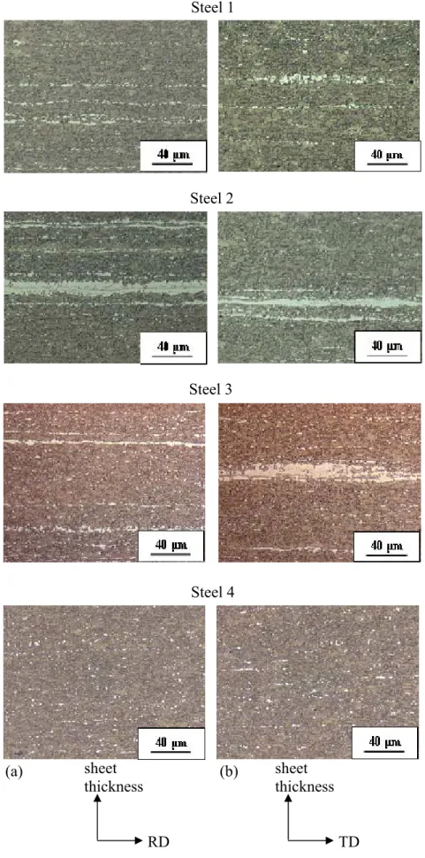
The first chapter is devoted to a literature survey on both bendability, TRIP steels and the origin of the micro and macrosegregations. Then, using scanning electron and light microscopy, a first microstructural characterization of the four studied materials is given. Finally, based on tensile and bending tests, a mechanical analysis of the four steels is proposed.
After this state-of-the-art survey and after a short presentation of the four TRIP-aided steels studied, the approach of this study is explained in more detail. The outline of the three other chapters will thus be given at the end of the first chapter.
Aciers très haute résistance pour application automobile
Les exigences environnementales actuelles requièrent que les émissions de gaz à effet de serre et de CO2 soient réduites. A cet effet, des normes européennes imposent aux
constructeurs automobiles une réduction de la consommation des véhicules ainsi qu’une diminution des émissions de CO2. Pour atteindre ces exigences, les industries automobiles
doivent utiliser des tôles plus fines avec des résistances plus élevées et des propriétés d’usage équivalentes ou améliorées. C’est dans ce contexte industriel que les aciéristes développent et proposent des aciers Très Haute Résistance (THR) qui ont l’avantage de réduire le poids des véhicules tout en gardant une haute résistance. Ces aciers sont couramment utilisés dans la caisse en blanc (squelette structurel de la voiture) pour les pièces de structure et de sécurité telles que les poutres de renfort ou les poutres de pare-choc (Figure 1).
Figure 1. Application des aciers très haute résistance
Les aciers très haute résistance regroupent trois grandes familles :
- Dual Phase (DP): aciers composés de phases dures (martensite ou martensite/bainite) dispersées dans une matrice ductile de ferrite. La combinaison haute résistance/ductilité et la forte capacité d’écrouissage font de ces aciers des candidats très fiables pour des pièces de structures ou de renforts tels que les longerons ou les traverses.
- TRIP (TRansformation Induced Plasticity): aciers composés d’une matrice ductile de ferrite contenant des petits îlots de bainite et d’austénite résiduelle. Ces aciers offrent un potentiel de durcissement supplémentaire par rapport aux DP grâce à la possibilité d’activer la transformation martensitique de l’austénite au cours de la déformation. Leur grande ductilité en font également des aciers de choix pour les pièces de structures ou de sécurité.
- Multiphase (MP): ces aciers ont une structure ferrito-bainitique très fine ou une structure bainitique durcie par des précipités ou alors une structure bainite-martensite. Ces aciers ont un bon compromis résistance/ductilité, une haute limite élastique “Re“, de bonnes caractéristiques de formage et une très bonne soudabilité par points. Ces aciers sont utilisés pour des pièces automobiles de sécurité destinées à la résistance aux chocs tels que longerons ou les renforts de portières.
La principale qualité des ces aciers est d’offrir un bon compromis entre résistance et ductilité (Figure 2). Dans ce graphique, nous pouvons constater que les aciers TRIP offrent un meilleur compromis entre résistance en traction et allongement à rupture. C’est pour cette raison que ces aciers sont très demandés par l’industrie automobile.
En effet, ils diffèrent des aciers conventionnels de part leur remarquable combinaison résistance/ductilité, résultant de leurs microstructures. La capacité d’écrouissage des TRIP est considérable, assurant une distribution de la déformation efficace pendant leur mise en forme. En raison de leur forte capacité d’absorption des chocs et de leur bonne résistance à la fatigue, les aciers TRIP sont particulièrement utilisés pour des pièces de structures et de sécurité tels que les traverses, les longerons, les renforts, etc.
Figure 2. Résistance en traction en fonction de l’allongement à rupture pour différentes familles d’aciers
Route métallurgique des aciers TRIP
La figure 3 illustre la route métallurgique des aciers TRIP. Après la coulée continue, la brame va suivre trois étapes : le laminage à chaud, le bobinage et enfin le laminage à froid. Après le laminage à froid, le matériau s’est durci donc le recuit (Figure 4) va permettre de recristalliser les grains et de produire des aciers TRIP ayant les propriétés demandées par les clients. Cette étape permet de restaurer une certaine ductilité nécessaire pour la mise en forme des tôles. Le cycle de recuit illustré à la Figure 4 correspond à celui des TRIP étudiés (avec un passage à la galvanisation). Pendant le chauffage et le maintien entre Ac1 et Ac3, la microstructure initialement ferrito/perlitique
est recristallisée pour atteindre à la fin du maintien une microstructure composée d’environ 60 % de ferrite et 40 % d’austénite. Cette distribution dépend de la température de maintien et plus elle est élevée, plus la quantité d’austénite formée est importante. Cette étape est suivi par un refroidissement entre 30 et 60°C/s assurant germination, croissance et grossissement de la ferrite. Ce refroidissement doit être assez rapide pour éviter la formation de perlite.
Pour stabiliser l’austénite grâce à son enrichissement en carbone, un maintien isotherme dans la région bainitique est effectué. Lors de cette étape, une partie de l’austénite est transformée en bainite. Il faut noter qu’en présence d’aluminium et de silicium, la bainite formée est sans Fe3C.
Après cette étape, l’acier est trempé dans un bain de Zn à 460°C avant d’entrer dans un four pour former le revêtement GA (alliage Zn-Fe).
Le refroidissement final entraîne une transformation partielle de l’austénite en martensite, surtout à mi-épaisseur qui est particulièrement enrichie en C et Mn. A la fin de ce recuit, l’austénite restante est appelée austénite résiduelle et représente 8 à 20 % de l’acier.
Figure 3. Production des aciers TRIP
Figure 4. Traitement thermique des aciers TRIP
Mise en forme des tôles par emboutissage
Dans l’industrie automobile, la plupart des pièces sont embouties pour leur donner leur forme finale. En fonction de la pièce désirée, le procédé d’emboutissage varie et il est parfois nécessaire d’effectuer plusieurs emboutissages pour obtenir des pièces automobiles avec des formes plus ou moins complexes.
Cependant, sur les nouveaux grades d’aciers TRIP ayant des propriétés mécaniques de plus en plus élevées, des fissures apparaissent sur les rayons des pièces embouties (Figure 5). Relier les propriétés de mise en forme des aciers avec leurs propriétés mécaniques classiques semblent maintenant insuffisant.
Il est donc nécessaire de prendre en compte la microstructure de ces aciers pour étudier plus précisément leur comportement en pliage.
Time (s) T e m per a tu re ( °C ) Ac1 Ac3 Refroidissement Chauffage Maintien intercritique Maintien dans la région bainitique Temps (s) Refroidissement final Coulée continue Refroidissement et bobinage Laminage à froid Produit laminé à chaud Recuit continu Produit laminé à froid Skin-pass Galvanisation
Figure 5. Poutre de pare-choc fissurée au niveau d’un pli après emboutissage
Problématique et démarche de l’étude
Pour élargir l’utilisation des aciers THR pour les pièces de structure, les limites des propriétés en mise en forme doivent être connues et une caractérisation est nécessaire pour aider au développement de ces nouveaux grades d’aciers. Ainsi, la compréhension de la mise en forme des aciers THR pour application automobile implique une étude détaillée des mécanismes d’endommagement pendant les essais de mise en forme.
Le but de ce travail est donc d’étudier les relations entre microstructure et capacité au pliage des aciers THR.
Les aciers TRIP peuvent généralement être emboutis plus facilement que les autres aciers. De plus, ils sont développés dans le but d’effectuer des pièces aux formes très complexes. Il est ainsi nécessaire d’étudier plus particulièrement ces aciers. Dans cette étude, quatre aciers TRIP présentant des performances en pliage différentes et des microstructures variées ont été utilisés. Deux tests de pliage ont particulièrement été étudiés : le pliage en V et le pliage sous traction.
Les principaux objectifs de ce projet sont:
- Effectuer les liens entre microstructure et endommagement pendant les tests de pliage.
- Etudier d’une manière quantitative, dans le cas particulier des aciers TRIP, le principal paramètre microstructural qui contrôle la fissuration en pliage.
- Proposer un outil permettant aux ingénieurs métallurgistes de tester d’une manière simple des voies d’amélioration métallurgique des aciers THR vis à vis de leur performance en pliage.
Ce manuscrit est constitué de quatre chapitres:
Le premier chapitre est consacré à l’état de l’art concernant à la fois le pliage, les aciers TRIP ainsi que l’origine des micro et macroségrégations. Dans une deuxième étape, une caractérisation à la fois microstructurale et mécanique des quatre aciers étudiés est effectuée.
Après cet état de l’art et une présentation rapide des quatre matériaux de l’étude, il sera possible d’expliquer plus en détail l’approche de cette étude. La démarche des trois autres chapitres sera donnée à la fin du premier chapitre.
Chapter 1
Characterization of the bendability of
TRIP steels
In the following part, a literature survey on bending tests and a short presentation of TRIP steels was given.
Four TRIP steels were chosen in this study to investigate and characterize their bendability.
No clear correlation between bendability and both usual mechanical properties and microstructural features have been observed.
Therefore, it is necessary to develop a more detailed mechanical / microstructural analysis of failure in bending.
Table of contents
I. LITERATURE SURVEY ... 13
I.A. Bendability of sheet metals ... 13 I.B. TRIP steels... 26 I.C. Banded structures formation... 30
II. MICROSTRUCTURAL CHARACTERIZATION OF THE FOUR TRIP-AIDED STEELS STUDIED... 36
II.A. Chemical composition and phase morphology ... 36 II.B. Determination of the retained austenite content... 40 II.C. Nanohardness of ferrite matrix and secondary phases... 43 II.D. Summary ... 44
III. MECHANICAL CHARACTERIZATION OF THE FOUR TRIP-AIDED STEELS STUDIED... 46
III.A. Tensile properties at room temperature ... 46 III.B. V bending properties... 47 III.C. Stretch bending properties ... 49 III.D. Summary... 51
IV. SUMMARY OF CHAPTER 1 ... 51 V. CHOICE OF THE MATERIALS AND SCOPE OF THE STUDY... 52
V.A. Choice of the materials ... 52 V.B. Outline of three other chapters... 52
I. Literature survey
I.A. Bendability of sheet metals
The formability of sheet metals often refers to the limit of strain or stress states up to which the forming process is accomplished successfully.
It is very difficult, however, to find suitable strain limit for sheet bending operations. The bending limit could be defined as the amount of strain that initiates a crack at the outer surface of the bending zone, from which a minimum bending radius is deduced. It is affected by many testing and material parameters, such as the tool geometry, bending procedure, material properties, sheet thickness and the surface or edge condition of the sheet. Note that information provided in this part is the more precise as possible. When information is missing, it is mean that all data were not mentioned in the various studies. Bending tests can be classified in three categories: simple bending, stretch bending and draw-bending. The two last categories correspond to bending under tension and differ from the first test where bending is applied without tension. It is important to distinguish pure bending by appliance of a torque on both sides from 3 points bending which induces both pure bending and a little tension.
1. Impact of specimen dimension and mode of preparation
One of the most significant parameters for this type of test is the surface state of cut edges. Indeed, the blanking process creates a section with three areas: a rollover (edge rounding), a sheared zone and a fracture zone (including the burr), Figure I.1.
The last one is generally the most problematic as it may introduce lot of incipient damage which will further develop under a stress field. Moreover, strain hardening due to cutting will increase the hardness of the material over a significant depth, reducing locally ductility.
Rollover Sheared zone Fracture zone
Burr
Figure I.1 : Cut edge of a dual phase steel sheet (cross-section micro light optical micrograph) (Dalloz et al., 2007).
To perform a bending test, it is necessary, before any other operation, to grind the surface of the edges. Indeed, the bending test is considered as valid (no artefact due to specimen preparation) only if edge effect is negligible. This means that a crack should start from the middle of sample width and not from the edge.
In addition, the sample width has a non-negligible influence on the allowed minimal bend. It is easier to bend samples with decreasing width because the necessary stress to bend the
sample will be lower. Moreover, a very wide sample leads to plane strain field whereas for a narrow one, the stress state is closer to uniaxial tension.
A study done on a copper-alloyed material shows that the minimal bending radius can be doubled if sample width increases from one to ten times the material thickness (Figure I.2). This tendency becomes blurred for higher values of width. We can also imagine that this dependency on specimen width should vary according to the ductility of material (Determe, 1998).
Figure I.2: Minimum bending radius evolution according to sample width for copper alloys (CuFe2P) with
various values of thickness (Determe, 1998).
2. Impact of microstructure
The first cause of material damage is generally the presence of internal inhomogeneities. For steels, we can distinguish various categories of defects, which are:
- Inclusions
- Microstructural heterogeneities.
Col (2010) showed that in presence of manganese sulphides (MnS), the bendability of a steel sheet may be lowered due to the initiation of a crack at this type of inclusion (Figure I.3). The material in this picture is a hot rolled mild steel of 1.5mm thickness.
Figure I.3. Crack due to a MnS on a wheel rim element (Col, 2010).
Such inhomogeneities can induce heterogeneous behaviour. Their location and orientation, often elongated along the rolling direction, favour crack development along the transverse direction. This can explain differences in bending behaviour noticed between rolling and transverse directions (Figure I.4). Indeed, sheet bend along transverse direction has generally a lower bendability. This effect was observed by Leu et al. (1997) where a poor bendability was noticed on transverse bent specimens.
Figure I.4 : Bend orientation with respect to the coil (Determe, 1998).
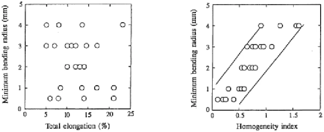
Yamazaki et al. (1995) showed that the bendability of UHSS with a tensile strength higher than 780MPa correlates better with microstructural homogeneity than with total elongation. In their study, they evaluated the bendability of steels by placing a specimen over a 90° V-block, forcing a punch of specified tip radius into the specimen, and measuring the minimum bending radius at which the specimen did not crack. Before bending, they performed hardness measurements on various sheets with various levels of microstructural homogeneity. Rockwell hardness was measured at five points with 2mm intervals from the surface of sheet specimens, and its standard deviation was taken as a microstructural homogeneity index. The minimum bending radius does not correlate at all with the total elongation in tension but fits quite well with the microstructural homogeneity index (Figure I.5). In their study, they measured the strain distribution of the bend surface and showed that higher strains were found for ferritic areas while lower strains were measured for martensitic areas. In addition, cracks are initiated at the boundary between high-strain portions and low-strain portions, i.e. between the hard and soft phases.
Figure I.5. Bending radius vs. total elongation and microstructural homogeneity index (Yamazaki et al., 1995).
Nagataki et al. (1994) worked on bendability of UHSS with fully martensitic structure having tensile strength ranging from 1100 to 1650 MPa and a thickness of 1.4mm. They showed that the microstructure should be refined and homogenized for the improvement of bendability.
From a few years, health and cleanliness of steels have been improved. This induces a decreasing of inclusions into steels. Moreover with the increase use of UHSS, inclusions still have an influence on the bendability but heterogeneities of microstructure (difference between hard and soft phases in multiphase steels for example) seem to have the most important role on the bendability of materials.
3. Relationships between bendability and other In Use Properties
Mechanical properties such as yield strength, tensile strength, strain hardening, reduction of area in tensile test, etc can be tentatively used to characterize the formability of a sheet. However, these values are not the most reliable parameters to predict the bendability of sheets.
To investigate pure bending of anisotropic sheet metals, Leu et al. (1997) proposed a simplified approach to identify the bending instability using the “maximum bending moment” concept, with the incorporation of the normal anisotropic R-value (defined as the ratio of the transverse plastic strain in the plane of the sheet to the plastic strain through the thickness) and the strain hardening exponent “n”. The value of R is given by the following averaging: R = (R0 + 2 R45 + R90) / 4 where R0, R45 and R90 are the Lankford coefficients at 0°, 45° and 90° with respect to the rolling direction of the sheet.
They showed that the springback is almost proportional to the normal anisotropic value R and decreases sharply with decreasing strain hardening exponent “n”. Concerning pure bending, the authors have shown that the minimum bending radius is proportional to the sheet thickness and decreases with the normal anisotropy “R” and the strain hardening exponent “n”. However, this trend was not confirmed by Yamazaki et al. (1995) who showed that the minimum bending radius was not correlated with the strain hardening exponent. In this paper, sheet was bent on a 90° V-block contrary to Leu’s study where pure bending was assumed.
Datsko et al. (1960) predicted the minimum bending radius for several materials (magnesium, aluminium, 1018 steel, cast-iron and titanium), from the reduction of area determined by a standard tensile test. They assumed that the fracture strain in the outer fibre of a bending specimen equals the one in tensile test specimens. The material assumed to be homogeneous, isotropic and the sheet was assumed to be bent in plane strain conditions. In their paper, they determined several equations allowing linking the Rmin (smallest radius that a material can withstand without cracking) to the Ra% (reduction of area) with various location of the neutral fibre. In their study, three-point bending test was used to determine the minimum bending angle as well as another bending method which provided similar results.
In case where the neutral fibre coincides with the mid-thickness the following equation can be used: 1 % 50 − = Ra t R (1)
According to the authors, this equation is only valid for Ra% < 20. When there is a shift in the neutral fibre, the equation (2) is chosen:
1 % 60 − = Ra t R (2)
The Forming limit curve (FLC) can also be used to predict the bendability of a material. For example, Sriram et al. (2003) performed stretch bending tests on various steels such as
DP800, DP980) with thicknesses ranging from 0.6mm to 1.8mm. Strains were measured in the failed samples both in the unsupported sidewall region and on the punch nose and compared with the corresponding achievable limit strain determined by the empirical FLC. These authors introduced a new element to define the stretch bending ability of UHSS within a wide range of R/t ratios and introduced a new concept called “stretch bendability index”. The purpose of the index is to isolate the stretching influence from coupled stretch-bend condition. This index represents the ability of the material to withstand stretching in the presence of severe bending.
The stretch bendability index is expressed as a ratio: A / B (Figure I.6). B is the limit strain (from FLC) for a given strain path and A is the maximum major hoop strain in the unsupported sidewall region for a given R/t ratio when the failure occurs at the punch nose. The maximum achievable value of the stretch bendability index is 1.
Figure I.6. Strain path and stretch bendability index (SBI) for 0.93mm BH210 specimens (Sriram et al., 2003).
In Figure I.7, it is noticed that the R/t value for a stretch bendability index (SBI) of 1 represents the critical R/t ratio (R/t)c for stretch bending for a given steel grade. For R/t ratios below (R/t)c, bending severity limits achievable formability. For R/t ratios higher than (R/t)c, the effect of bending on the achievable formability is minimal.
4. Failure modes
a. Simple bending
In their work, Nagataki et al. (1994) observed fracture surfaces of specimens tempered at 400°C after bending with an inside radius close to 0 mm. They showed that fracture in bending occurs by shear mode crack propagation followed by void nucleation. Steninger et al. (1982) worked on steels with tensile strength ranging from 240 to 390 MPa and a thickness of 5 mm. They performed V-bending tests on these specimens and observed cracks on outer surfaces of the specimens. Fracture propagated along shear bands and voids expanded preferentially along the shear direction.
Chien et al. (2004) reviewed two most commonly found failure modes: necking (which involves void nucleation, growth and coalescence) and shear localization. The bendability of aluminium sheets was investigated with the shear localization mode. For example, the pictures of three samples bent with three different radii are shown in Figure I.8.
Note that there is a high indentation of the punch especially for specimen bent with lower punches (radii of 0.3mm and 0.4mm).
Figure I.8. Cross-sections of AA6111 specimens (aluminium sheet) with an initial thickness of 1mm. These specimens were subjected to bending in a semi-guided wrap-bend test with bending radii of: (a) 0.6 mm, (b) 0.4 mm and (c) 0.3mm (Chien et al., 2004).
Vallellano et al. (2008) analysed the effect of strain gradient in stretch bending on the failure of metal sheets. Depending on the severity on the gradient, two kinds of failure are expected: a necking-controlled failure and a fracture-controlled failure. They showed that the sheet failure is controlled by the ability of the less strained fibres (inner fibres) to neck. This idea is consistent with the work reported by Tharrett and Stoughton (2003). In fact, they observed necking on the sheet when the strain on the concave side of the sheet reached the in-plane forming limit strain. A conservative failure criterion is to assume that the sheet fails once the outer fibre fails. This criterion is obviously not new and has been successfully checked in a variety of bending operations (Ragab and Saleh, 2005).
b. Stretch bending
Demeri (1981) performed stretch bending tests on several steels (AK steels with tensile strength of 300MPa, HSLA-F50 and DP 80 with tensile strength of 680MPa) and on one aluminium sheet (2036-T4) with thicknesses ranging from 0.5mm to 2.5mm in order to determine the influence of material and geometrical variables on sheet metal formability. Data obtained are curves relating the punch radius “R”, the sheet thickness “t” to the height of the configuration at failure “H” (cf. Figure I.9 for AK steels).
For AK steel, fracture location depends on three factors: (i) punch radius, (ii) sheet thickness and (iii) transverse constraints. The curves obtained for the various materials could be divided into two regions:
i) predominantly stretching for values of (R/t) > 20 ii) predominantly bending for values of (R/t) < 20.
Indeed, for most of steel grades, failure moved from the punch contact region to the unsupported sidewall with increasing the R/t ratio.
Figure I.9. (a) Stretch bent test, (b) Bendability curves for AK steel sheets (Demeri, 1981).
Damborg (1998) used another type of stretch bending test to determine the stretch bendability of sheets. For that purpose, he carried out tests on two steels: HSLA (550 MPa, 1.5mm) and DQSK (Draw Quality Silicon Killed with 365MPa and 1.5mm thickness) and one aluminium alloy (Al 6022-T4 with 330MPa and 0.9mm thickness) with various punch radii and various tension loads (Figure I.10). Thanks to this test, he also noticed the two possible fracture modes in stretch bending: bending or stretching fracture (Figure I.10).
Figure I.10. Schematics of a bending under tension test, illustrating the typical location of the bending and stretching fracture (Damborg, 1998).
Sriram et al. (2003) found similar results in stretch bending (Figure I.11) except for some DP steels where, even for for high R/t ratios, failure did not move from the punch nose to the sidewall. In other words, DP steels were found to be more sensitive to bending fracture (with respect to stretching fracture) than the other steels. According to the authors, the different behaviour of DP steels is not clearly understood. They assumed that steel processing, chemistry and distribution of martensite may influence its forming behaviour.
Figure I.11. (a) Stretch bending device, (b) Height at failure as a function of R/t ratio for structural steels in stretch bending (Sriram et al., 2003).
To summarize, in simple bending, cracks seem to initiate from the surface (on the bent nose) and propagate along shear direction. This will be discussed in the following parts. In addition, from the above mentioned results, the height at failure during a stretch bending test can be expressed as a function of R/t. Moreover, several authors claimed that above a critical ratio (R/t)c, failures move from the punch nose to the sidewall, which means that above (R/t)c, stretching is predominant over bending.
5. Mechanical description of the bending tests
a. Analytical models
To simulate as well as possible what happens in material during bending, the stress and strain distributions have to be known within the bent specimen.
During bending solicitation, strain goes from elastic to plastic modes until fracture. During the elastic stage, stress repartition is homogeneous with:
- a zero value at neutral fibre
- a compression stress next to inner radius - a tensile stress next to outer radius
Beranger et al. (1994) demonstrates that in pure bending, the neutral fibre is exactly at mid-thickness (Figure I.12a). When tension appears in bending and in presence of friction, this assumption is not true and thus the neutral fibre moves within the material due to thickness reduction of sheet steel (Figure I.12b).
Figure I.12 : Stress distribution: a) pure bending b) bending + friction + tensile (Beranger et al., 1994).
In simple bending, without applied tension, and where the radius of curvature is more than several times the sheet thickness, the neutral fibre approximately coincides with the mid-thickness (Figure I.13) so that the axial strain εcan be given by the following equation:
) 1 ln( ) ( 0 R y y = + ε (3)
Where R0 corresponds to the radius at thickness and y is the distance from the mid-thickness.
Figure I.13: Strain and stress distribution for a material in pure bending that obeys the relation n k 1
1 ε
σ =
In various studies (Chakrabarty et al., 2000; Chakrabarty et al., 2001, Livatyali et al., 2003; Quach et al., 2004; Ragab et al., 2005), the true bending strain was defined as equation (3). However, other authors developed more accurate equations to determine the bending strain. For example, Zhang et al. (1998) used the following equation:
) 2 1 ln( 2 1 0 0 0 ε ε ε = + + − e R y (4)
where ε0 is the strain at the neutral fibre. When the neutral fibre is undeformed, the value
ε0 becomes equal to zero. In this case, equations (3) and (4) can be approximated by the same following value:
0
R y
≈
ε (5)
Wu et al. (2006) defined the bending strain at the outer fibre with the following equation:
⎟ ⎟ ⎟ ⎟ ⎟ ⎠ ⎞ ⎜ ⎜ ⎜ ⎜ ⎜ ⎝ ⎛ ⎟⎟ ⎠ ⎞ ⎜⎜ ⎝ ⎛ + + = 0 0 1 2 1 ln R t R t ε (6)
Lemoine et al. (2009) compared the reliability of these formulas and showed that they are all equivalent till a ratio thickness / bending radius equal to 0.1. For t/R > 0.1, significant difference appear between these formulas (with y = t / 2, i.e. at the outer surface).
Analytical and semi-analytical models have been widely adopted in the study of bending process (Leu, 1997; Zhang et al., 1998; Chakrabarty et al., 2000 and 2001; Quach et al., 2004 and Ragab et al., 2005). Unfortunately, these models are generally used with significant simplifications and simple constitutive equations laws (i.e. without damage) and thus, the accuracy of the results are considerably affected. Therefore to avoid these problems and to increase the accuracy of these models, finite-element simulation is needed.
b. Need of numerical simulation to predict the bendability of sheet
The understanding and development of bending mechanics are aimed at obtaining important information for industrial applications: (i) springback prediction to determine accurately the final dimensions of bent parts, (ii) bendability and fracture prediction, (iii) estimation of the bending force reached during these tests and (iv) contact issues between punch and sheet. As the fracture in bending is a localized phenomenon, it is intended to model very accurately this test to access to strain and stress fields. Therefore, the numerical simulation thanks to a finite-element method is generally used to model precisely bending tests.
Only few numerical works can be found in literature concerning the modelling of bending tests and prediction of fracture. Most finite-element simulations of bending tests focused
on the prediction of springback (Date et al., 1999; Gan and Wagoner, 2004). In order to correctly predict bendability and fracture in bending tests, it is necessary to include a damage criterion in the model and to select a suitable one, accurate knowledge of damage mechanisms is essential. In the case of sheet-metal forming, a lot of authors studied the mechanisms leading to final failure and proposed their own models.
The formability approaches can be classified in three main families: (i) Forming Limit Diagrams (FLD) approaches which are based on strain fields and dedicated to sheet metal forming (Keeler and Backofen, 1964; Goodwin, 1968) (ii) coupled damage approaches and (iii) uncoupled damage approaches.
For many sheet forming processed, the FLD has been used for the evaluation of failure. Laukonis and Ghosh (1978) and Graf and Hosford (1993) showed that FLD are only valid with proportional strain path. However, for bending tests, the stress/strain state changes continuously and so the strain path does not stay constant. In order to solve this issue, other failure criterions were used.
Considering coupled damage approaches, damage evolution is considered within the elastoplastic material law and fracture is then fulfilled when the damage variable reaches a critical value. Gurson (1977) was one of those who develop a ductile damage macroscopic constitutive law based on microvoid growth. Its model was largely used and extended in the literature (Tvergaard, 1982; Tvergaard and Needleman, 1984). The Gurson model is the first micromechanical model for ductile fracture which introduces a strong coupling between deformation and damage. It is derived from an analysis similar to the one performed by Rice & Tracey (1969) for an isolated void. Other scientists as Lemaitre (1985) also developed damage formulation fully coupled with the behaviour laws of elasto-plasticity.
Eventually, uncoupled damage approaches also named “fracture criterion” are used as soon as the failure is fulfilled when the stress and/or the strain state reaches a critical value To model forming tests including failure criterion, several finite-element analysis exist in the literature (Table I.1). The main aim of these numerical simulations generally consisted in the prediction of bendability, failure location and estimation of the stress and strain fields. Note that most of the authors used an isotropic hardening law with either an anisotropic yield criterion (Hill generally) or an isotropic criterion (Von Mises). According to the authors who chose a mixed (isotropic+kinematic) hardening law, results were well predicted and best results were obtained than with an isotropic hardening law.
Material Thick. Forming tests 2D/3D Constitutive equation criterion Failure Main results Reference 2024-O aluminium alloy 1.02mm air bending in U or V-shape 2D: Plane strain Isotropic hardening + Hill No fracture criterion Springback prediction Wang et al. 1993 mild steel 0.67mm deep drawing test 3D Isotropic hardening + Hill Extension of Gurson-Tvergaard model Prediction of localized necking and damage Brunet et al. 1996 mild steel & high strength steel 1.2mm and 1.4mm Cyclic 3-point bending test 3D (i) isotropic (ii) kinematic (iii) mixed hardening + Von Mises No fracture criterion Best prediction of the bendability with mixed hardening Zhao and Lee 2002 0.6% carbon steel (780MPa) 3mm air bending test 3D Isotropic hardening + Von Mises Rice and Tracey Prediction of damage evolution and F/d curve Hambli et al. 2004 HSLA 500 4mm wiping-die bending test 3D Isotropic hardening + Von Mises Lemaitre Prediction of stress Bahloul et al. 2006 Orthotropic thin sheet Hydrobul ging test 3D Mixed hardening + Hill continuum damage mechanics Prediction of fracture location Saanouni and Badreddine 2007 HSLA 4mm wiping-die bending test 3D Isotropic hardening + Von Mises Lemaitre Prediction of failure and load
Mkaddem and Bahloul 2007 galvanized BH220 1mm Nakazima test 3D Isotropic hardening + Von Mises GTN Prediction of local crack initiation Uthaisangs uk et al. 2008 DP980 draw bend test 3D Isotropic hardening + Von Mises No fracture criterion Prediction of failure and F/d curves Kim et al. 2009 DP600 1.2mm Nakazima test 3D Isotropic hardening + Barlat Gologanu model Prediction of failure, F/d curves and strain
fields Falkinger et al. 2010 DP780 1mm stretch bending test (i)3D, (ii)plane strain and (iii)shell element s Isotropic hardening + Hill MMC fracture model Prediction of failure, F/d curves and strain
and stress fields (best agreement with 3D) Luo et Wierzbicki 2010 DP600 4mm pure bending test 2D: plane strain Mixed hardening + Hill extended Gurson model Prediction of bendability Bettaieb et al. 2010
6. Summary
To conclude on this part, it was first noticed that several parameters can influence the bendability of steels (mechanical properties, microstructure, tools, etc…) making difficult the understanding of formability issue. Among them, microstructural parameters, in particular heterogeneities, seem to have a key role in bending operation.
Secondly, it was shown that, in bending tests, failure propagate by a shear mode and seem to initiate from the outer surface in air-bending test and appear either at the punch nose or in the sidewall in stretch bending tests depending on the bending conditions.
Finally, it is highlighted that finite-element numerical simulation is an efficient tool to accurately relate global bending performance to mechanical behaviour and predict failure mechanisms at microstructural scale. It was shown that a mixed hardening law coupled with anisotropic criterion provides the best combination to accurately predict bendability. Almost analyses were carried out with a coupled damage approach and most of them used 3D modelling except for simple bending test where 2D simulation with plane strain condition was sufficient.
I.B. TRIP steels
1. Definition
Low alloy TRIP-aided steels (which will be termed “TRIP steels” throughout this manuscript for the sake of simplicity) are composed of a ductile ferrite matrix containing small islands of hard bainite, martensite and retained austenite. Transformation of retained austenite into martensite during deformation causes significant strain hardening and delays the onset of necking, providing high ductility. It is the “TRansformation Induced Plasticity” (TRIP) effect that forms the basis of the exceptional properties of the TRIP steels.
These steels differ from conventional steels by their remarkable combination of high strength and ductility, resulting from their particular microstructures. The hardening capacity of the TRIP steels is considerable, ensuring efficient strain redistribution during forming and hence good drawability, combined with very high yield strength in the finished component.
Due to their high energy absorption capacity, TRIP steels are principally used for structural and safety automotive parts such as longitudinal beams, seat structures, etc.
2. Processing of TRIP steels
It was shown (Rigsbee and van der Arend, 1977; Speich and Miller, 1979) that retained austenite contained in Dual Phase steel permits the improvement of their mechanical properties.
If austenite is stable enough, the mechanical strength and the ductility are increased. The stabilization is performed after the intercritical annealing. During the bainitic transformation, austenite is supersaturated in carbon, ensuring its stability.
In order to obtain a multiphased structure with retained austenite, the thermal cycle used for DP steel is modified by introducing holding in the bainitic domain (Matsumura et al., 1987). Figure I.14 illustrates heat cycles for cold rolled DP steels (a) and TRIP steels (b).
Figure I.14. Heat treatment cycle and microstructures (a) DP steels (b) TRIP steels. F: ferrite; A: austenite; B: bainite; M: martensite (Matsumura et al., 1987).
The evolution of the microstructure during the TRIP steel process is shown in Figure I.15 with:
(i) ferrite and austenite during the intercritical annealing
(ii) austenite decomposition and ferrite nucleation at grain boundary
Figure I.15. Microstructure formation during the thermal cycle. α = ferrite, αb = bainite, γ = austenite,
γr= retained austenite (Ohlert et al., 2002).
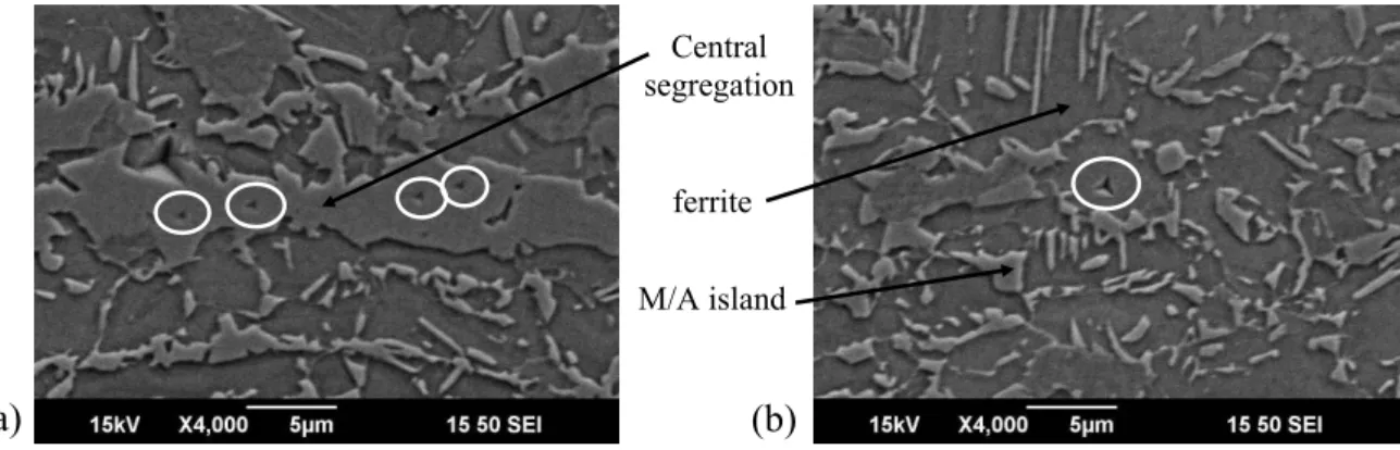
At room temperature, the microstructure of these TRIP steels is composed of ferrite, bainite, retained austenite and sometimes martensite. A typical microstructure of a TRIP steel by SEM is shown in Figure I.16.
Figure I.16. Typical microstructure of a TRIP steel by SEM. F = ferrite, A = retained austenite and B = bainite (Jacques et al., 2002).
3. Role of retained austenite
In the case of DP steel, mechanical properties are mainly due to the interaction between a hard phase (martensite) and a soft phase (ferrite). For TRIP steels, the progressive transformation of retained austenite into martensite, coupled with the multiphased microstructure are the factors responsible for their mechanical properties.
Destabilization of retained austenite can be caused by plastic deformation (Pickering, 1992). This transformation induced by mechanical loading improves the mechanical properties of low-alloy TRIP steels with dispersed retained austenite islands (Haidemenopoulos et al., 1989; Jacques, 1998).
Retained austenite influences the mechanical properties thanks to both its stability and its distribution: too instable retained austenite is transformed into martensite too early, so that necking cannot be efficiently delayed. On the contrary, if the retained austenite is too stable, the martensitic transformation does not occur and the positive effect on delaying necking is cancelled. Therefore, austenite should have the right good stability to ensure progressive martensitic transformation during straining.