HAL Id: hal-02065697
https://hal.insa-toulouse.fr/hal-02065697
Submitted on 12 Mar 2019HAL is a multi-disciplinary open access archive for the deposit and dissemination of sci-entific research documents, whether they are pub-lished or not. The documents may come from
L’archive ouverte pluridisciplinaire HAL, est destinée au dépôt et à la diffusion de documents scientifiques de niveau recherche, publiés ou non, émanant des établissements d’enseignement et de
EMBEDDED MECHATRONIC SYSTEMS:
APPLICATION TO ELECTRICAL THRUST
REVERSER ACTUATION SYSTEMS
Scott Delbecq, Marc Budinger, Jérôme Piaton
To cite this version:
Scott Delbecq, Marc Budinger, Jérôme Piaton. A MORE INTEGRATED DESIGN APPROACH FOR EMBEDDED MECHATRONIC SYSTEMS: APPLICATION TO ELECTRICAL THRUST RE-VERSER ACTUATION SYSTEMS. ICAS 2018, Congres of the International Council of the Aero-nautical Sciences, Sep 2018, Belo Horizonte, Brazil. �hal-02065697�
A MORE INTEGRATED DESIGN APPROACH FOR
EMBEDDED MECHATRONIC SYSTEMS: APPLICATION TO
ELECTRICAL THRUST REVERSER ACTUATION SYSTEMS
Scott Delbecq1,2 , Marc Budinger2, Jérôme Piaton1
1Safran Electronics & Defense ,2ICA, Université de Toulouse, CNRS
Keywords: Sizing, Multidisciplinary System Design Optimization, Design Space Exploration, Electromechanical Actuator, Thrust Reverser
Abstract
The design of embedded mechatronic systems like electromechanical actuation systems volves heterogeneous knowledge due to the in-terference of several engineering specializations and the multiple physical laws that govern their behaviour. This results in costly iterations dur-ing the design process and non-optimal solutions. Multidisciplinary System Design Optimization techniques provide theoretical foundations and computational tools for optimizing large and multidisciplinary systems. The approach taken uses these techniques within a proposed design and sizing methodology. It allows a holistic siz-ing of mechatronic engineersiz-ing systems with em-phasis placed on reusability and rapid decision making. This methodology has been applied in an industrial context to size an electrical thrust re-verser actuation system. This more integrated de-sign approach has resulted in de-significant assess-ments and insights in early trade-off studies for this complex aircraft subsystem.
1 Introduction
Environmental protection is a key driver for next generation aircrafts as drastic goals of Flightpath 2050 are asked by ACARE european council [1]. In order to reduce drastically fuel burn, emis-sions and noise, new aircraft concepts have been proposed. They investigate innovative propul-sion systems [2], propulpropul-sion-airframe integration
for boundary layer ingestion [3], structural al-loys, systems and equipment architectures. One research axis consists in electrifying propulsion, systems and equipment by betting on the advan-tages of electrical technologies in terms of inte-gration, maintenance and power efficiency. More than ever, this more electrical aircraft course of action is driving the research and technology of the aeronautical industry and academics. The research axes that concerns non-propulsive sys-tems can be separated in two main axes. The first axis investigates the concept of bleedless aircrafts which consists in replacing pneumatic systems by electrical systems. The second axis investi-gates the concept of hydraulicless aircrafts which consists in replacing hydraulic systems by elec-trical systems. These elecelec-trical systems are more eco-friendly than hydraulic systems due to the re-moval of irritating Skydrol fluid, more efficient and are also easier to integrate and maintain. The hydraulicless aircraft concept has lead to the elec-trification of actuation systems for flight controls [4], landing gears [5] and thrust reversers.
The integration of these new technologies increases risks of unexpected and critical be-haviours of systems leading to costly re-designs. These new electrical systems have to prove that they meet the severe reliability and availability requirements of commercial aircraft when oper-ating in a harsh vibratory and thermal environ-ment. Therefore, one of the challenges for devel-oping a more electrical aircraft is to master the
design and integration of the forthcoming mecha-tronic systems like actuation systems. Hence, emphasis must be placed on developing new de-sign approaches and methodologies to dede-sign and size these new technologies that would ensure an optimized and successful integration during fu-ture aircraft developments. In parallel, Multidis-ciplinary Design Optimization (MDO) tools have significantly increased in sophistication in the re-cent decades. Thus, they have lead to many ap-plications such as aircraft conceptual design (0D analytic models), aircraft trajectory optimization (0D-1D lumped parameter models) or high fi-delity wing design (3D Finite Element Method models).
This paper will focus on a developed de-signs and sizing methodology and its applica-tion to electrical thrust reverser actuaapplica-tion systems (ETRAS). For that, the paper is organized as fol-lows. Section 2 presents the methodology and its associated framework. Section 3 outlines the architecture, design drivers and sizing scenarios of the ETRAS. Section 4 describes the modelling tasks achieved for this case study. Section 5 presents the design optimization/exploration for-mulation and the results obtained. Conclusions and future work are presented in Section 6.
2 Sizing methodology and associated
frame-work
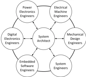
The design of mechatronic systems involves sev-eral stakeholders which have different type of en-gineering specialization knowledge. The knowl-edge is available in different engineering teams of the design office as shown in Fig. 1.
During system design the design drivers of the system are well known by the system archi-tect which enables him to manage the other en-gineering specializations (electronics, electrical machine design, mechanical design, software...) design tasks. The other engineering special-ization experts are well aware of technological limits of their components and therefore assess rapidly their performances.
Experienced system architects are able to make system design trade-offs without
inter-System Architect Electrical Machine Engineers Power Electronics Engineers Digital Electronics Engineers Embedded Software Engineers System Engineers Mechanical Design Engineers
Fig. 1 Different engineering teams and
knowl-edge flows
acting with other engineering specialization ex-perts. However, for unconventional systems or in the absence of a multi-domain experienced sys-tem architects it is not possible. The proposed methodology permits better consideration for en-gineering specialization knowledge during sys-tem sizing. A methodology consists in a process, methods and a framework. This section is orga-nized as so.
2.1 Process
A process can be defined as successive steps. The first step consists in the definition of require-ments, design drivers and sizing scenarios of the system. Once sizing scenarios are defined, mod-elling needs are identified and modmod-elling activi-ties can be outlined. The second step is thus the implementation of the models requested for siz-ing. The third steps assembles elementary mod-els into reusable groups that are manageable by a single individual. These groups correspond to component level sizing models. The fourth step assembles these component sizing models to form a complete system sizing model. In the fifth step, the system sizing model is analyzed and op-timized. The final and sixth step explores the de-sign space using the system sizing model. The next part summarizes these steps and outlines the associated methods.
A more integrated design approach for embedded mechatronic systems: Application to Electrical Thrust Reverser Actuation Systems
2.2 Methods
2.2.1 Step 1: Requirements, design drivers and
sizing scenarios definition
The definition of requirements, design drivers and sizing scenarios has to be achieved through exchange of information between stakeholders during early development phase. The informa-tion consists in design knowledge represent needs and constraints of each of the stakeholders. These needs and constraints are translated into require-ments and design drivers used to design and size the system. An efficient method to represent each of this knowledge and their interaction is through a system breakdown structure. Nodes represent components, their design drivers and the sizing scenarios. Using different shapes of nodes help distinguish them.
2.2.2 Step 2: Elementary computational model
generation
In order to provide low computational cost mod-els, the elementary computational model used are algebraic. Algebraic models can be gener-ated using different methods. Analytic models can be obtained by deriving equations represent-ing the laws of physics. Scalrepresent-ing laws are al-gebraic equations based on reference component [6]. Linear regression of component data sheets provide the possibility to obtain algebraic model that compute component geometrical parame-ters (length, mass) with respect to performances (torque, speed). Surrogate modelling can be used to fit empirical data or simulation data. Surro-gate modelling techniques that generate algebraic models using Finite Element Method (FEM) sim-ulations are available [7]. Surrogate modelling can also be used for representing lumped param-eter simulations.
2.2.3 Step 3: Elementary models assembly into
reusable component sizing models
The assembly of elementary algebraic models enables to use acausal modelling for increasing reusability of models. The combination of graph-based methods and symbolic computation
meth-ods provides techniques to implement an acausal environment. Such methods also permit to detect computation singularities. This step enables to generate flexible inputs/outputs component siz-ing models composed of elementary algebraic models whilst checking their solvability.
2.2.4 Step 4: Component sizing models
assem-bly into a system sizing model
The assembly of component sizing models to form a total system sizing model is intricate be-cause of interconnections between variables that come from the system layer. The method used to represent the system model is the N2 diagram [8]. It is a diagram that represents in the shape of a matrix the functional or physical interfaces between system elements. In addition, a hierar-chical decomposition method is used to deal with the complexity of system containing a large num-ber of elements.
2.2.5 Step 5: Analysis and optimization using
the system sizing model
Analysis and optimization using the system siz-ing model can be achieved ussiz-ing Multidisci-plinary System Design Optimization techniques. Gradient-based methods are used with symbolic differentiation for elementary models derivatives and Unified Derivatives Equations [9] for total derivatives. This leads to low analysis and opti-mization times which is very interesting for rapid decision making during the sizing process.
2.2.6 Step 6: Design space exploration using
the system sizing model
Design space exploration using the system siz-ing model can be achieved ussiz-ing Multidisci-plinary System Design Optimization techniques for multidisciplinary analysis and Design of Ex-periments. Visualization methods like parallel coordinates and scatter plots provide efficient features for design and sizing purposes.
2.3 Framework
Step 3 to 6 are supported by a in-house frame-work called BOA (Bind your models, Optimize your system, Accelerate your design) [10]. To match the process this framework is decomposed in four environments: Block Generation, Sizing Procedure, Design and Exploration. It was devel-oped using Python programming language. The computational core relies on key scientific com-puting packages like Scipy, Numpy, Sympy, Net-workX, pyDOE and OpenMDAO [11]. The user interface was implemented using PyQt5. Fig. 2 illustrates the user interface of the sizing proce-dure environment. Design variable block Input block Objective block Causal block
Fig. 2 Sizing Procedure environment
This framework has been used to achieve the sizing of aileron rotary [12] and linear [13] elec-tromechanical actuators and more recently a pri-mary flight control actuation system [14]. For the first time, it is used to achieve a conceptual sizing of an ETRAS. This example is described in the following sections. The problem is non-exhaustive but includes the main challenges of ETRAS design and sizing.
3 Architecture, design drivers and sizing
sce-narios
The ETRAS is supplied by the AC voltage net-work of the aircraft. It has to deploy and stow the engine nacelle transcowl(s) during landing. The transcowl is part of the thrust reverser system and can have either two symmetrical transcowls (C-duct) or one same transcowl (O-(C-duct). A O-duct transcowl is considered in this case study.
3.1 Architecture
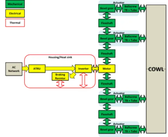
The ETRAS includes an electrical power chain and an electromechanical power chain. The elec-trical power chain main components are an Auto-transformer Rectifier Unit (ATRU), an inverter, a braking resistor and a housing. The electrome-chanical power chain main components are a brushless motor, flexshafts and linear actuators. This architecture is illustrated in Fig. 3.
Actuator Actuator Actuator Actuator Housing/Heat sink ATRU Motor Braking Resistor Inverter AC Network Flexshaft Flexshaft Ballscrew TB + Tube Ballscrew TB + Tube Bevel gear Flexshaft Ballscrew TB + Tube Ballscrew TB + Tube Flexshaft Bevel gear Bevel gear Bevel gear COWL Mechanical Electrical Thermal
Fig. 3 ETRAS power architecture
The ATRU includes an autotransformer, two rectifiers and two interphase inductors. An actu-ator includes a bevel gear, a thrust bearing, a ball screw and its tube (housing). We focus here on the sizing of components that have a significant effect on the total mass of the system. Hence, the sizing of the system includes the autotransformer, the braking resistor, the housing which acts as a heat sink for the braking resistor and inverter, the motor, flexshafts and actuators.
3.2 Design drivers
The system design drivers considered for this study are the requirements such as fail-safe sys-tem, aerodynamic loads and the transcowl mass. The Aborted Take Off (ATO) deploy and stow performances are specified as a maximum time to achieve full stroke. Hence, position/speed mis-sion profile for both sequences are considered as a system design driver.
Design drivers are given for each component. The main design driver of the autotransformer,
A more integrated design approach for embedded mechatronic systems: Application to Electrical Thrust Reverser Actuation Systems the braking resistor and the housing is their
max-imum operating temperature. Since the ETRAS application is very short (typically a few sec-onds), only heat capacities of components are used to estimate there maximum temperature. The braking resistor is also selected on its peak power. The braking resistor resistance has also to be carefully adapted to DC bus voltage. The main design drivers of brushless motors for dy-namic and transient applications are maximum torque, maximum speed, maximum temperature and inertia. For flexshafts their maximum/fatigue torque and maximum speed are technological limits whereas rotational stiffness and inertia par-asitic characteristics. Bevel gears are selected on their reduction ratio and maximum/fatigue torque whereas inertia is a parasitic characteristic that has an effect on the sizing problem. Thrust bear-ings are selected using the maximum/fatigue ax-ial force. The main design drivers of ball screws are their pitch, the maximum/fatigue axial force and axial stiffness.
3.3 Sizing scenarios
The first sizing scenario considered is the ATO deploy at cold temperatures (high friction in actu-ators and flexshafts). The torque and speed mis-sion profile depends on the deploy position/speed profile, inertias, transcowl mass, aerodynamic loads and mechanical efficiency. It has an signif-icant effect on motor maximum torque and speed and the autotransformer peak power. The aero-dynamic load are position dependent. The de-ploy sequence begins with a phase where the mo-tor drives the transcowl and follows with a phase where the motor brakes the transcowl and thus generates energy.
The second sizing scenario considered is the ATO deploy at hot temperatures (low friction in actuators and flexshafts). The high mechanical efficiency leads to more braking torque for the motor, higher peak power ad more energy to dis-sipate for the braking resistor.
The third sizing scenario taken into account is the stow at cold temperatures. Loads are smaller that the ATO deploy but there is no braking phase
so the motor is always driving the transcowl. Hence, it does not determine peak torque or power for motor and autotransformer but gener-ate important energy losses that they have to con-tain thanks to their intrinsic heat capacity.
The fourth and fifth sizing scenarios taken into account are jamming failure modes. As the system has to be fail-safe, all components shall resist to such event. The loads taken are for ATO deploy. The stress generated in mechanical com-ponents depends on inertias, stiffness, transcowl mass and motor torque/speed operating point at jamming.
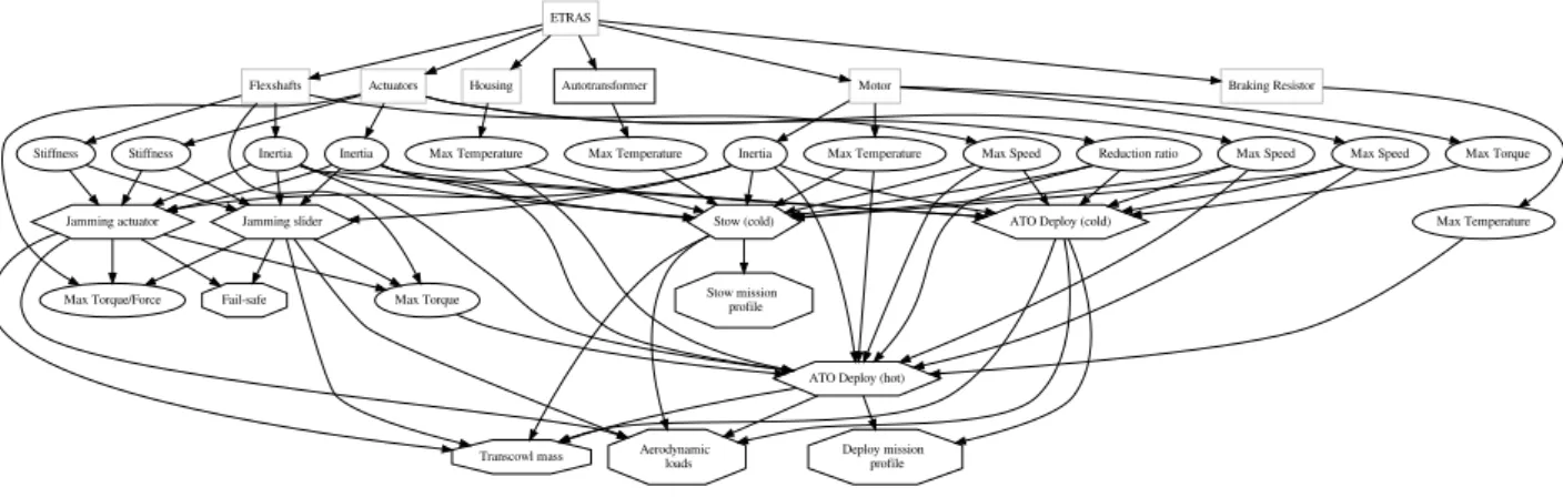
Fig. 4 outlines the architecture considered for the sizing problem, the different design drivers and sizing scenarios as well as their interactions and therefore the high complexity of the ETRAS design.
4 Sizing models
The sizing models used enable to compute the quantity of interest of sizing scenarios. Estima-tion models are also used to determine to compo-nent parameters involve in sizing scenarios mod-els. Efforts are made to use algebraic models for optimization by introducing 0D models (scaling laws, analytic), surrogate models of 0D-1D (Dy-mola) and 3D models (FEM).
4.1 Sizing scenarios models
A surrogate model of lumped parameter model simulation is used to represent ATO deploy (cold and hot) and stow (cold). A 0D-1D lumped pa-rameter model is achieved using Dymola Soft-ware. It computes the maximum power, torque, speed and energy at transcowl level during mo-tor and generamo-tor (Deploy only) phases with re-spect to aerodynamic loads, total inertia of the system and a one degree of freedom trapezoidal speed profile. The trapezoidal speed profile is im-plemented so that the only degree of freedom is maximum speed at transcowl level. The model uses the inverse simulation features of Dymola as shown in Fig. 5.
sam-ETRAS
Autotransformer Braking Resistor Housing Motor
Flexshafts Actuators
Max Temperature
Max Temperature Max Temperature Inertia Max Temperature Max Speed Max Torque
Max Torque
Max Speed Stiffness Inertia
Max Torque/Force
Max Speed Stiffness Inertia Reduction ratio
ATO Deploy (cold)
ATO Deploy (hot) Stow (cold) Jamming slider Jamming actuator Stow mission profile Deploy mission profile Aerodynamic loads Transcowl mass Fail-safe
Fig. 4 Non-exhaustive system breakdown graph of the ETRAS sizing problem with component design
drivers (oval), system design drivers (octogone) and sizing scenarios (hexagone)
Kinematics + aerodynamic loads
Fig. 5 Stow mission profile model at transcowl
level in Dymola
ples is achieved on total system reflected inertia and speed profile parameter. The simulations are executed using a co-simulation Functional Mock-up Unit. Post-analysis computes the quantity of interest (energy, peak power...) for each simula-tion and then a third-order polynomial response surface surrogate is used to represent them with respect to total system inertia and speed profile parameter.
As the ETRAS operates during a very short time, components maximum temperature sizing scenario are computed with respect to the equiv-alent energy of losses and heat capacity.
Maximum speed of motor and flexshafts are checked using analytic models.
Jamming sizing scenarios models compute the peak torque/force applied on mechanical components with respect to inertias, stiffness, aerodynamic loads, motor torque and speed.
They use an analytic model (Equation 1) that as-sumes that the equivalent kinetic energy of spin-ning inertias is transformed into potential elastic energy of mechanical stiffness.
Fjam=
q
MeqKeqV2 (1)
Where Fjam is the jamming force, V the
equiv-alent mass’s (Meq) speed and Keq the equivalent
stiffness at the jamming point.
4.2 Estimation models
The autotransformer sizing is achieved using scaling laws and an existing design. The auto-transformer is sized for constant magnetic satura-tion as it operates during a very short time. How-ever, the thermal behaviour has to be checked. Hence, the heat capacity is also estimated using a scaling law.
The braking resistor electrical resistance and thermal resistance are obtained using manufac-turer analytic model. The housing heat capacity, which acts as a heat sink for the braking resis-tor and the inverter, is obtained with an analytic model.
The motor electromagnetic model is obtained using surrogate modelling of FEM simulations (Fig. 5). It considers the magnetic saturation of the core material. It computes the electro-magnetic torque with respect to three high level variables, the stator diameter, the yoke thickness
A more integrated design approach for embedded mechatronic systems: Application to Electrical Thrust Reverser Actuation Systems and current density in the windings. Models that
compute Joules and iron losses are also imple-mented. Details of this model can be found in [7].
Fig. 6 Brushless motor electromagnetic FEM
model using FEMM
Flexshafts diameter, stiffness (Equation 2), inertia and mass are estimated using scaling laws with respect to peak torque.
Kf s= G−1lre f( Tf s Tf sre f)
4
3L−1f s (2)
Where Kf s is the flexshaft stiffness, Glre f and
Tf sre f respectively the linear torsional deflection
and peak torque of a reference flexshaft, Tf s the
flexshaft peak torque and Lf s the length of the
flexshaft.
The bevel gear is sized using a scaling law that assumes the tooth contact stress to be the main effect on gear mass.
Ball screw parameters are estimated using scaling laws with respect to peak axial load. However, buckling load is check using a scaling law as well.
Thrust bearing scaling law assumes Hertz contact stress as the main design driver.
4.3 System sizing model
The system sizing model assembles all the sizing scenarios and parameter estimation models. The mission profile analysis evaluates the ATO de-ploy (cold and hot) and Stow (cold) with respect their respective speed profile parameter and total system inertia. It analyzes the more constrain-ing variables in the different operatconstrain-ing quad-rants for the components sizing such as maxi-mum speed, maximaxi-mum load and energy. These
sizing inputs are then distributed to the different component sizing bricks. The system level de-sign variables are two speed profile parameters, spur gears reduction ratio, motor stator diameter, yoke thickness and current density. The system level outputs of the sizing model are autotrans-former, braking resistor, housing and motor tem-peratures. Motor and flexshaft maximum speeds have also to be evaluated.
The sizing problem includes two multidisci-plinary couplings. First, the total system inertia is required to compute mission profile analysis but is evaluated using the inertia of components esti-mated with respect to the outputs of mission pro-file analysis. The second multidisciplinary cou-pling comes from the jamming scenarios. The in-ertias and stiffness of components are required to achieve jamming load analysis but are evaluated using components sizing models that require the value of this jamming load. Hence, these multi-disciplinary couplings have to be solved to pro-vide a consistent design solution.
A Multidisciplinary System Design Opti-mization monolythic formulation is used to solve them. It consists in adding a normalized de-sign variable and an inequality constraint for each coupling and the system total mass as an objec-tive. For example, the first coupling can be de-scribed by:
Fnom= f (Js, α)
Js= g(Fnom)
(3)
Where Fnomis the nominal force from the mission
profile analysis, α the ATO deploy speed profile
parameter and Jsthe system total inertia.
Is transformed into: Fnom= kos· h(α) Js= g(Fnom) Fnom≥ f (Js, α) (4) Where h = f (Js=0,α).
This formulation has a lighter computational cost compared to other monolythic formulations like Individual Discipline Feasible (IDF) or All At Once (AAO) [15]. Nevertheless, the use of the inequality is only possible because decreasing
the nominal force Fnomdecreases the total system
mass and that is the objective.
5 Design optimization and exploration
5.1 Formulation
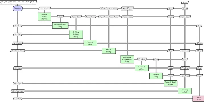
The representation of the system sizing model and optimization problem is given in Fig. 7 using the Extended Design Structure Matrix diagram [16].
The sizing optimization implemented
mini-mizes the total mass of the ETRAS Mtot with
re-spect to deploy and stow speed profile parameter
αd, αs, motor diameter Dmot, yoke thickness ey,
current density Jcur and consistency variables for
mission profile load analysis kosF and jamming
scenario kosjam. The constraints come from
tech-nological limits of components like maximum
speed Ω∗ and maximum temperature Θ∗. Two
consistency constraints introduced previously are used to solve the two multidisciplinary couplings. The optimization problem formulation is the fol-lowing:
minimize Mtot
with respect to αd, αs, Nred, Dmot,
ey, Jcur, kosF, kosjam
subject to Ωmot− Ωmotmax ≤0
Ωf s− Ωf smax≤0
Fdyn− Fnom≤0
Fjams− Fnommech≤0 Fjambs− Fnommech ≤0
Θat− Θatmax ≤0
Θhous− Θhousmax ≤0
Θbr− Θbrmax ≤0
Θmot− Θmotmax ≤0
(5)
Performing this optimization provides the possibility to assess rapidly integration parame-ters such as mass and dimensions of the system in order to make system integration trade-offs.
For example such sizing code can assess the effect of changes of requirements like deploy time on the total system mass. In addition, the
effect of changes of technologies like motor iner-tia can be evaluated rapidly.
5.2 Results
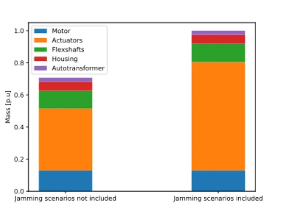
The study of the effect sizing scenarios on the global design is used to illustrate both the utiliza-tion of the methodology and the sizing problem. The sizing scenarios such as jamming and many other have to be included in the design in order to avoid non-compliant design solutions. Fig. 8 outlines optimization results in terms of mass breakdown of the ETRAS when considering and not considering the slider jamming and ball screw jamming.
Jamming scenarios not included Jamming scenarios included 0.0 0.2 0.4 0.6 0.8 1.0 Mass [p.u] Motor Actuators Flexshafts Housing Autotransformer
Fig. 8 Mass breakdown optimization results
without (left) and with (right) jamming scenarios
Results show that these jamming scenarios have a significant impact on the mass of the actu-ators. As they are the main source of mass, it di-rectly impacts the system total mass. Therefore, emphasis must be placed on implementing siz-ing codes that enable the consideration of a large number of sizing scenarios, design variables and design constraints.
5.3 Discussions
The proposed more integrated design approach uses a in-house framework. This framework provides the possibility to capitalize the knowl-edge through sizing models libraries and sizing projects libraries. This way sizing scenarios can be reused for other projects. This is a tremendous feature as generations of experts have started to
A more integrated design approach for embedded mechatronic systems: Application to Electrical Thrust Reverser Actuation Systems
α(0) d, α (0) s, N(0) red, D (0) mot, e(0)y, J(0) cur, kt,(0) osF, k t,(0) osjam Mcowl Optimizer αd, αs, kt
osF Nred, Dmot, ey, Jcur Nred, k
t
osjam Nred Nred
Mission profile analysis
Emot Egen, Pmax Egen, Emot Egen, Emot, Fnom, Vmax Fnom, Vmax Fnom Faero, Vmax
g1: Θat Autotransformersizing Mat
g2: Θbr
Braking Resistor sizing
g3: Θhous Housingsizing Mhous
g4: Θmot, Ωmot Motorsizing Jmot Jmot, Tem Mmot
Mechanical components loads Tf s, Ωf s Fact Fact g5: Ωf s Flexshaftsizing Jf s Jf s, Kf s Mf s Actuator
sizing Jact Jact, Kact Mact
gc
1: Fdyn Dynamic loadanalysis
gc
2: Fjamslider
Jamming analysis
f : Mtot Totalmass
Fig. 7 XDSM diagram for the ETRAS sizing optimization problem retire and leave organizations with their precious
expertise. The sizing scenarios of the ETRAS case study presented in this paper come from the main design drivers of the system. Nevertheless, the sizing of the ETRAS includes also scenar-ios that have not been taken into account such as geometric integration or different voltage/power supply configurations. However, this confirms that design sizing methodologies are mandatory to design such complex systems in a holistic and tightly coupled manner.
6 Conclusion and future work
The more electrical aircraft course of action has lead to the integration of new electrical technolo-gies like electromechanical actuation systems. The introduction of such technologies requires to developed design and sizing methodologies in or-der to achieve successful developments. Such de-sign and sizing methodology and its associated in-house framework have been outlined. It en-ables to integrate different engineering special-ization knowledge to achieve a holistic sizing of the system. This permits to capitalize expertise knowledge throughout the design process that can be reused easily for forthcoming projects. In
addition, the framework includes rapid optimiza-tion and exploraoptimiza-tion capabilities as emphasis is placed on rapid decision-making during early de-sign phases. Then, this methodology was applied to the sizing of an ETRAS where a large num-ber of disciplines and scenarios, various types of models (0D,1D,3D) and multiple couplings were involved as typical MDO applications.
This paper has shown that it is possible to in-tegrate and capitalize different engineering spe-cialization expertise in one same design and siz-ing environment. The ETRAS had not yet been treated in scientific literature. This paper is an introduction to the complexity of such system as only the main sizing scenarios were considered. However, this offers interesting perspectives for future work. The mission profile has a significant effect on the total system sizing. Hence, future work will include the optimization of both mis-sion profile and motor control strategies.
References
[1] Kallas S, Geoghegan-Quinn M, Darecki M, Edelstenne C, Enders T, Fernandez E and Hart-man, P. Flightpath 2050 europe’s vision for avi-ation. Report of the High Level Group on
Avia-tion Research, European Commission, Brussels, Belgium, 2011.
[2] Charier G and Gallet F. System of com-pact contra-rotating propellers. U.S. Patent No. 9,057,326., 2015.
[3] Gray J, Mader C, Kenway G and Martins J. Modeling boundary layer ingestion using a cou-pled aeropropulsive analysis. Journal of Air-craft, Vol. 55, No. 3, pp 1191-1199, 2017. [4] Van Den Bossche D . Model Based Design and
Experimental Validation of Electro-mechanic Actuator Systems for a Nose Landing Gear. Proc International Congress of the Aeronauti-cal Sciences, Hamburg, Germany, 2006. [5] Doberstein D and Thielecke F. Model Based
Design and Experimental Validation of Electro-mechanic Actuator Systems for a Nose Landing Gear. Proc International Congress of the Aero-nautical Sciences, Brisbane, Australia, 2012. [6] Budinger M, Liscouët J, Hospital F and Maré
J-C. Estimation models for the preliminary de-sign of electromechanical actuators. Institution of Mechanical Engineers, Part G: Journal of Aerospace Engineering, 226(3), 243-259, 2012. [7] Sanchez F, Budinger M and Hazyuk I. Dimen-sional analysis and surrogate models for the thermal modeling of Multiphysics systems. Ap-plied Thermal Engineering, 10, 758-771, 2017. [8] Kapurch S J. NASA systems engineering
hand-book. Diane Publishing, 2010.
[9] Martins J R and Hwang J T. Review and unifi-cation of methods for computing derivatives of multidisciplinary computational models. AIAA journal, 51(11), 2582-2599, 2013.
[10] Delbecq S, Budinger M, Hazyuk I, Sanchez F and Piaton J. A framework for sizing embedded mechatronic systems during preliminary design. Proc IFAC-PapersOnLine, 50(1):4354 – 4359, Toulouse, France, 2017.
[11] Gray J, Moore K and Naylor B. OpenM-DAO: An open source framework for mul-tidisciplinary analysis and optimization. 13th AIAA/ISSMO Multidisciplinary Analysis Opti-mization Conference, Fort Worth, Texas, USA, 2010.
[12] Sanchez F and Delbecq S. Surrogate model-ing technique for the conceptual and prelimi-nary design of embedded actuation systems and
components. Proc International Congress of the Aeronautical Sciences, Daejeon, Korea, 2016. [13] Delbecq S, Tajan F, Budinger M, Maré J.-C and
Sanchez F. A framework for the conceptual and preliminary design of embedded mechatronic systems. Proc International Workshop on air-craft System Technologies, Hamburg, Germany, 2017.
[14] Delbecq S, Budinger M, Piaton J, Daguse B. Optimization of primary flight control actuation system using parametric sizing models of actu-ators, power electronics and structural analysis. Recent Advances in Aerospace Actuation Sys-tems and Components, Toulouse, France, 2018. [15] Martins J R and Lambe A. Multidisciplinary Design Optimization: A Survey of Architec-tures. AIAA journal, 51(9), 2049-2075, 2013. [16] Lambe A and Martins J R. Extensions to the
de-sign structure matrix for the description of mul-tidisciplinary design, analysis, and optimization processes. Structural and Multidisciplinary Op-timization, 46(2), 273-284, 2012.
Contact Author Email Address
mailto: [email protected] mailto: [email protected]
Copyright Statement
The authors confirm that they, and/or their company or organization, hold copyright on all of the origi-nal material included in this paper. The authors also confirm that they have obtained permission, from the copyright holder of any third party material included in this paper, to publish it as part of their paper. The authors confirm that they give permission, or have ob-tained permission from the copyright holder of this paper, for the publication and distribution of this pa-per as part of the ICAS proceedings or as individual off-prints from the proceedings.