HAL Id: hal-01808190
https://hal.archives-ouvertes.fr/hal-01808190
Submitted on 5 Jun 2018HAL is a multi-disciplinary open access archive for the deposit and dissemination of sci-entific research documents, whether they are pub-lished or not. The documents may come from teaching and research institutions in France or abroad, or from public or private research centers.
L’archive ouverte pluridisciplinaire HAL, est destinée au dépôt et à la diffusion de documents scientifiques de niveau recherche, publiés ou non, émanant des établissements d’enseignement et de recherche français ou étrangers, des laboratoires publics ou privés.
Chatter Control in Turning Process with a Nonlinear
Energy Sink
Etienne Gourc, Sébastien Seguy, Guilhem Michon, Alain Berlioz
To cite this version:
Etienne Gourc, Sébastien Seguy, Guilhem Michon, Alain Berlioz. Chatter Control in Turning Process with a Nonlinear Energy Sink. Advanced Materials Research, Trans Tech Publications, 2013, 698, pp.89-98. �10.4028/www.scientific.net/AMR.698.89�. �hal-01808190�
Chatter control in turning process with a nonlinear energy sink
Etienne GOURC
1,a, Sébastien SEGUY
1,b, Guilhem MICHON
2,cand Alain BERLIOZ
3,d1
Université de Toulouse; INSA; ICA (Institut Clément Ader); 135 avenue de Rangueil, F-31077 Toulouse cedex 4, France
2
Université de Toulouse; ISAE; ICA (Institut Clément Ader); 10 avenue Édouard Belin, F-31055 Toulouse cedex 4, France
3
Université de Toulouse; UPS; ICA (Institut Clément Ader); 118 route de Narbonne, F-31062 Toulouse cedex 4, France
a
[email protected], b [email protected], c [email protected],
d
[email protected] Keywords: Dynamical, Turning, Nonlinear Energy Sink, Chatter.
Abstract. This paper presents the interest of an original absorber of vibration in order to reduce chatter vibration in turning process. The device is composed of a linear oscillator corresponding to a flexible cutting tool – subject to chatter – strongly coupled to a Nonlinear Energy Sink (NES), with purely cubic stiffness. The novelty of this work is the use of a nonlinear cutting law, more accurate for modeling the cutting process. The delayed equations of motion are analyzed using a combination of the method of multiple scales and harmonic balance. Different types of responses regimes are revealed such as periodic response and also Strongly Modulated Response (SMR). Analytic results are then compared with numerical simulations. Finally, the potential of the NES is demonstrated to control chatter in turning process.
Introduction
Surface quality of parts produced by machining operation is strongly affected by the well-known regenerative chatter. The chatter instability is induced by the time delay between two consecutive workpiece revolutions. By the effect of some external disturbance, the tool start damped oscillations relative to the workpiece, and the surface roughness is undulated. For two consecutive workpiece revolutions, the chip thickness is modulated. This regenerative mechanism is well known and was presented first by Tobias [1]. Since this work, many researchers have improved the knowledge by the stability lobe representation, see e.g. [2,3,4,5]. The behavior of a cutting tool on a lathe has also been studied using the method of multiple scales [6].
Various techniques for chatter suppression have been investigated. In [7], a variable spindle speed in milling was used to disturb the time delay. Another approach to reduce chatter is the use of linear tuned vibration absorbers. Recently, an analytical optimized method was presented for linear absorbers in the context of chatter [8]. These linear absorbers are successfully applied on boring process [9]. Active absorbers have been also proposed with piezoelectric tool [10]. However all these linear absorbers are limited by the small frequency bandwidth, and in practice their efficiency is not interesting for the machinist.
The idea of attaching a nonlinear oscillator to a lathe is relatively new [11,12]. In recent studies, it has been demonstrated that addition of a small mass attachment with a strong nonlinear coupling (i.e. a nonlinear energy sink) to a linear oscillator can be benefit for vibration mitigation [13,14], even in presence of gravity [15]. In [16], a general analytical procedure was presented. The possibility to control self-excitation regimes in a Van der Pol oscillator with a NES has been demonstrated in [17]. Systems with NES exhibit regimes that are not related to fixed points, and cannot be explained using local analysis [18]. These regimes are related to relaxation oscillations of the slow flow and are also interesting for passive control [12].
In this paper, the possibility of controlling regenerative chatter using a nonlinear energy sink is analyzed for turning process, including a nonlinear cutting law. Theoretical predictions are compared with numerical integration. In the next section, the model considered is described. In the third section, the asymptotic analysis of the equation of motion is performed. Then, the different response regimes accompanied with numerical simulation are presented.
Mechanical model
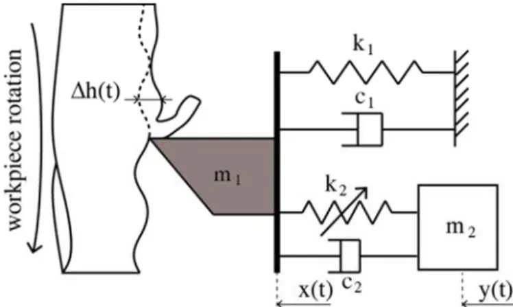
The model developed herein consists of a cutting tool on a lathe with an embedded NES. The cutting tool is assumed to vibrate only on its first flexible mode and the workpiece is considered to be rigid. A schematic of the model is given in Fig. 1.
Figure 1. Scheme of the model.
The governing equation of motion is as follow:
(1a)
m c r k y rx 0 (1b)
where x and y represent the tool tip and NES displacement respectively. m#, c# and k# (i 1, 2) are the mass, damping and stiffness of the tool and NES. r is the influence coefficient, depending on the position of the NES on the tool. Finally, F is the cutting force taking into account the regenerative effect. The cubic polynomial form due to Shi and Tobias [19] is expressed as follow:
F )h t , p ρ h t ρ h t ρ h t (2)
where p is the chip width (depth of cut), h t is the chip thickness and ρ# (i 1, 3) are specific cutting coefficient obtained by fitting the experimental cutting force measurement with a third order polynomial. The chip thickness h t is expressed as follow:
h t h0 ∆h t (3)
h0 represent the nominal chip thickness in the absence of vibration and ∆h t is the chip thickness variation gives by:
∆h t x t x t τ (4)
where x t τ is the delayed position of the tool and τ is the time delay between two workpiece revolutions τ 2π/Ω, with Ω the spindle speed. In the steady state, x t x0, y t y0. Substituting Eq. 3 and Eq. 4 into Eq. 1a, Eq.1b gives:
In the unsteady state, the displacement would be the sum of the steady state component and an unsteady component:
x t = x0 + u t , y t = y0+ v t (6)
Substituting Eq. 3, Eq. 5, Eq. 6 into Eq. 1a, Eq. 1b gives:
m + c + k x + c r − r + k rx − y r = −p α ∆h t + α ∆h t + α ∆h t (7a)
m + c − r + k y − rx = 0 (7b)
where α = ρ + 2ρ h0 + 3ρ h0 , α = ρ + 3ρ h0, α = ρ . Changes of variables are introduced as follow: 9ω , ω , μ , μ , ε, η, κ, β , β @ = ABC DC, B D , EC DCFC, E D FC, D DC, GHC DCFC , F FC , H HC, HI HCJ (8)
The time is rescaled t̃ = ω t, τL = ω τ. The nonlinear terms of the cutting law are also rescaled β = εβM, β = εβM. Dropping the tilde, the compact form of equation of motion are as follow:
uN + 2μ uO + u + 2εμ ruO − vO r + εκ ru − v r + η ∆h t + β ∆h t + β ∆h t = 0 (9a)
εvN + 2εμ rvO − uO + εκ rv − u = 0 (9b)
where the dots denotes differentiation with respect to time. Analysis of the linear system
The linear uncoupled system is obtained by setting ε = 0 in Eq. 9a:
uN + 2μ uO + u + η)u t − u t − τ , = 0 (10)
Eq. 10 admits solution of the form:
u t = u0eQR#F (11)
where ω is the frequency of the oscillations, γ is the grow or decay rate and u0 depends on initial conditions. Substituting Eq. 11 into Eq. 10 gives:
γ + iω + 2μ γ + iω + 1 + η)1 − eTU QR#F , = 0 (12)
At the stability boundary, γ = 0. It is possible to prove that this bifurcation γ, η, ω = 0, ηE, ωE is a Hopf bifurcation because it results from two complex conjugate eigenvalues. Splitting Eq. 12 into real and imaginary parts and setting γ = 0 yields:
1 − ωE + ηE 1 − cos ωEτ = 0 (13a)
2ωEμ + ηEsin ωEτ = 0 (13b)
Solving Eq. 13a, Eq. 13b for cos ωEτ and sin ωEτ and using trigonometric identity, the frequency of the bifurcated periodic orbit is obtained as:
ωE = 1 + ηE− 2μ ± Z ηE− 2μ − 4μ (14)
The stability boundary is often plot in the space of parameters Ω, η and is called stability lobes. Analysis of the coupled system
In this section the system with the NES is studied. First, a new coordinate representing the internal displacement of the NES is introduced:
w t = ru t − v t (15) Substituting Eq. 15 into Eq. 9a, Eq. 9b gives:
uN 2μ uO + u + 2εμ wOr + εκw r + η ∆h t + β ∆h t + β ∆h t = 0 (16a)
ε ruN − wN − 2εμ wO + εκw = 0 (16b)
System Eq. 16a, Eq. 16b cannot be analyzed using standard approach such as the method of multiple scales or the method of averaging due to the lack of linear stiffness in the NES equation. A mixed multiple scale/harmonic balance method proposed by Luongo [20] is used.
A detuning parameter representing the nearness of η to the critical value ηE is introduced as:
η ηE εσ (17)
A first order uniform approximation in the vicinity of the Hopf bifurcation has the form:
u t; ε = u0 T0, T + εu T0, T + ⋯ (18a)
w t; ε = w0 T0, T + εw T0, T + ⋯ (18b)
where Ta εat (n 0, 1, …). The time delay is considered of O 1 which is rather natural, since the most interesting zone for the machinist is close to the first Hopf lobe. The delayed position of the tool is expressed as:
u t − τ; ε = u0 T0− τ, T − ετ + εu T0− τ, T − ετ + ⋯ (19) which upon expansion for small ε becomes:
u t − τ; ε = u0 T0− τ, T + εu T0− τ, T + ⋯ (20)
Substituting Eq. 18a, Eq. 18b, Eq. 20 into Eq. 16a, Eq. 16b and equating coefficients of like power of ε yields: order ε0: D0u0 2μ D0u0+ u0+ ηE u0− u0U = 0 (21) order ε : D0u 2μ D0u + u + ηE u − u U = −2D0D u0− 2μ D u0− 2μ rD0w0 − ηEτD u0U− σ u0− u0U − ηEeβ u0− u0U + β u0 − u0U f − κrw0 (22a) D0w0 rD0u0+ 2μ D0w0+ κw0 = 0 (22b)
where DaD ∂D/ ∂TaD and uaU= ua T0− τ, T . The general solution of Eq. 21 can be expressed as:
u0 = A T e#Fijk+ ∑ mApaq a T e QnT#Fn jko + cc (23)
where cc stand for the complex conjugate of the preceding terms, ωE is the critical frequency of the oscillation at the boundary of Hopf bifurcation given in Eq. 14. γa− iωa are the remaining roots of Eq. 21. Close to the Hopf bifurcation, all the roots have negative real parts except one which change sign at the stability boundary as explained in [21]. After transient, all the roots decay with time and the long time behavior at O 1 is given by:
u0 = A T e#Fijk+ cc (24)
To study the effect of the NES and nonlinear terms, Eq. 22a, Eq. 22b at O ε are now analysed. Eq. 22b is first considered. Since this equation does not admit exact solution and since we are interested in the behavior of the system in the vicinity of the 1: 1 resonance, we seek a solution in the form of a one term Harmonic Balance expansion:
Substituting Eq. 24, Eq. 25 into Eq. 22b and balancing term of ωE frequency gives:
2iμ BωE+ 3κB Bt − BωE + rAωE = 0 (26)
Expressing A and B in polar form:
A Re#v, B Ne#x (27)
Substituting Eq. 27 into Eq. 26, splitting into real and imaginary part and rearanging gives: cos Δ = z)FiT {z , |}Fi (28a) sin Δ = −F~ zi|} (28b) R | Fz i •e 3κN − ωE + 4μ ωEf (28c)
where Δ δ θ. Setting Y R and Z N , Eq. 28c is rewritten as follow: Y | F„
i
•e 3κZ − ωE + 4μ ωEf (29)
Eq. 29 defines the Slow Invariant Manifold (SIM) of the problem. Depending on the value of μ , the SIM can consist either in one monotonous branch or admit extremums. To determine the critical value of μ , the derivative of the right hand side of Eq. 29 is equated to zero and solved for Z:
Z#
C
I…IFi±CI†FiT ~ ‡Fi
{ (30)
Consequently, the SIM will admit extremums if μ <
√ . By conducting a standard stability
analysis, it can be shown that if μ >
√ , the SIM will be constituted of only one stable branch, but
if μ <
√ , the SIM will be constituted of two stable divided by one unstable branch. This scenario
is typical with system that can perform relaxation-type oscillation. To investigate this possibility, Eq. 22a at 0 ε will be analysed.
Substituting Eq. 24, Eq. 25 into Eq. 22a and eliminating terms that produce secular terms with respect to e#Fijk gives:
−D A)2iωE+ 2μ + ηEτeT#FiU, − σA)1 − eT#FiU, − 3κrB Bt − 2iμ rωEB +
3ηEβ A At)e#FiU− 1, eT #FiU= 0 (31)
Expressing A and B in polar form, splitting into real and imaginary parts and rearranging gives: ΨD R
Nre3κN 2ωE− sin ωEτ ηEτ − 2μ ωE cos ωEτ ηEτ + 2μ f sin Δ + Nre−3κN 2μ +
cos ωEτ ηEτ + 2μ ωE sin ωEτ ηEτ − 2ωE f cos Δ − R −σ + 6R ηEβ cos ωEτ −
6R ηEβ τηEcos ωEτ − cos ωEτ τηE+ 2 cos ωEτ μ + τ sin ωEτ ηE− 2ωEsin ωEτ −
2μ (32)
where
Ψ 4ηEτ sin ωEτ ωE+ 4ηEτ cos ωEτ μ + ηEτ sin ωEτ + ηEτ cos ωEτ + 4ωE + 4μ
(33) Substituting Eq. 28a, Eq. 28b into Eq. 32 and multiplying by R the following equation governing the evolution of Y is obtained:
•ŽΨ• • 2‘•Ž•ecos •Ž’ ’“Ž − 2 cos •Ž’ ” − ’“Ž + 2•Žsin •Ž’ + 2” f +
4” •Ž–e2” “Ž’ cos •Ž’ 4” ” 2•Ž “Ž’ sin •Ž’ •Žf 6—•Ž – e2μ •Ž 4” •Ž
4” •Žsin •Ž’ “Ž’ cos •Ž’ “Ž’•Ž 2” sin •Ž’ “Ž’f 18— – e2” cos •Ž’ ’“Žf (34)
In order to understand the dynamics of the system qualitatively, it is only necessary to know how the fixed points are located on the SIM. This can be understood graphically as the intersection of the SIM and the two parabola obtained by setting the right hand side of Eq. 34 to zero and solving for Y.
Analysis of some response regimes
The behavior of an embedded NES on a lathe cutting tool has been previously studied in [12], it was shown that passive control of chatter by using a NES is possible and good correspondence between analytical prediction and numerical integration was observed. However, only a linear cutting law was considered. The aim of this section is to highlight the changes in the behavior due to the nonlinear terms in the cutting law. The integration scheme used for numerical simulation is the Matlab dde23 algorithm. First, the three passive control mechanisms for a linear cutting law are presented, and next, the behavior of the system comprising a nonlinear cutting law will be presented.
Linear cutting law. The linear cutting law is obtained by setting β β 0. The parameters used for the numerical simulations are:
ε 0.01, μ 0.05, μ 0.1, κ 1, ηE 0.12, τ 3.94, r 1 (35)
When a linear cutting law is considered, three control mechanisms are possible, depending on the value of the detuning parameter: complete suppression of chatter, stabilization of chatter and passive control of chatter through relaxation oscillation, also called Strongly Modulated Response (SMR).
The SIM of a small value of the detuning parameter (σ 0.1) is presented in Fig. 2(A). Two fixed points exists, one is stable and is located on the origin (denoted with a red circle), and the other one is unstable (red cross) and is located on the second stable branch of the SIM (not showed on the figure for visibility reason). The red circle and cross represents the stable and unstable fixed points, and the green line represents the projection of the temporal integration of the equations of motion on the SIM. In this case, the slow flow is repelled to the origin and chatter is fully suppressed. This scenario is confirmed by numerical integration presented in Fig. 2(B).
Figure 2. Case of complete suppression of chatter for the set of parameters (Eq. 35) and σ = 0.1 (A) Structure of the SIM. Solids and dashed blue lines represents the stable and unstable branch of the SIM respectively.
’o’ and ’+’ denotes stable and unstable fixed points. Green line represents the projection of numerical integration of the coupled system on the SIM. (B) Numerical verification; blue line : coupled system, green
line: uncoupled system.
For a higher value of the detuning parameter (σ 0.3 in Fig. 3(A)), the fixed points located at the origin becomes unstable, and a stable fixed points is now located on the first stable branch of the SIM. This corresponds to the stabilization of chatter, which induce small amplitude periodic oscillations of the tool. The numerical integration corresponding to this case is presented in Fig. 3(B).
Figure 3. Case of stabilization of chatter for the set of parameters (Eq. 35) and σ = 0.3. (A) Structure of the SIM. Solids and dashed blue lines represents the stable and unstable branch of the SIM respectively. ’o’ and ’+’ denotes stable and unstable fixed points. Green line represents the projection of numerical integration on
the SIM. (B) Numerical verification.
Increasing the value of the detuning parameter to ‘ 0.9, the previously stable fixed point cross the folded point – , and the only way for the slow flow is to perform relaxation oscillation, that is passive control of chatter through SMR. This response regime is also verified numerically in Fig. 4(B).
Figure 4. Case of passive control of chatter via SMR for the set of parameters (Eq. 35) and σ = 0.9 (A) Structure of the SIM. Solids and dashed blue lines represents the stable and unstable branch of the SIM respectively. ’o’ and ’+’ denotes stable and unstable fixed points. Green line represents the projection of
numerical integration on the SIM. (B) Numerical verification.
Nonlinear cutting law. The nonlinear contribution of the cutting law (β and β ) are sets to non-zero values. The same set of parameters (Eq. 35) is used and the nonlinear terms are: β β 10.
The SIM for σ 0.15 is presented in Fig. 5(A), the black dashed line represents the SIM at time scale T .
(A) (B)
Figure 5. Case of complete suppression of chatter for the set of parameters (Eq. 35) and σ = 0.15 (A) Structure of the SIM. Solids and dashed blue lines represents the stable and unstable branch of the SIM respectively. ’o’ and ’+’ denotes stable and unstable fixed points. Green line represents the projection of
numerical integration on the SIM. (B) Numerical verification.
It is observed that four fixed points are now located on the SIM. The stable fixed point is located at the origin, two unstable fixed points are located on the two stable branch of the SIM and another unstable fixed point is on the unstable branch of the SIM. In this case, if the initial conditions are below first unstable fixed points, the slow flow will be attracted directly by the stable fixed points and if the initial conditions are above the first unstable fixed points, the flow will perform a relaxation cycle before being attracted by the stable fixed point. This corresponds to complete suppression of chatter.
Increasing σ to σ 0.2 again for the same set of parameters, the SIM is presented in Fig. 6(A). The unstable fixed points on the first stable branch of the SIM is now located below the landing point Z . In this case, with initial conditions above the first unstable fixed points, since the landing point is higher than the unstable fixed points, the flow will be repelled to the unstable branch of the SIM, and the perform relaxation oscillation. This is confirmed by numerical integration in Fig. 6(B).
Figure 6. Case of passive control of chatter via SMR for the set of parameters (35) and σ = 0.2 (A) Structure of the SIM. Solids and dashed blue lines represents the stable and unstable branch of the SIM respectively.
’o’ and ’+’ denotes stable and unstable fixed points. Green line represents the projection of numerical integration on the SIM. (B) Numerical verification.
Another different configuration can be obtained with the following set of parameters (all the others parameters remain unchanged): κ 20, β 10, β 100.
The SIM in this case is displayed in Fig. 7(A). In this case, two stable fixed points are located on the first stable branch of the SIM. Depending on the initial conditions, the flow will be either attracted by the fixed points located at the origin, which correspond to a complete suppression of chatter, or by the other fixed points, which correspond to the stabilization of chatter. These scenarios are confirmed by numerical integration in Fig. 7(B).
(A) (B)
(A) Structure of the SIM. Solids and dashed blue lines represents the stable and unstable branch of the SIM respectively. ’o’ and ’+’ denotes stable and unstable fixed points. Green and purple line represents the
projection of numerical integration on the SIM. (B) Numerical verification. Conclusion
In this paper, the interest of a nonlinear absorber to reduce chatter vibration in turning process was studied.
The original device was composed of a linear oscillator corresponding to a flexible cutting tool, strongly coupled to a Nonlinear Energy Sink (NES). The NES was composed of a small mass attached with a purely nonlinear cubic stiffness. The originality of this work was the use of a nonlinear cutting law, in order to model the turning process. The model takes into account the delay term of the regenerative effect, the nonlinear term of the cutting law and the nonlinear stiffness of the NES. The whole system has been studied using a combination of the method of multiple scales and harmonic balance method. Different responses regimes were also discussed by studying the location of the fixed points on the Slow Invariant Manifold (SIM). Regimes are characterized by a complete suppression of chatter, a stabilization of chatter and a chatter control through relaxation cycle oscillations called SMR response. This study show that taking into account a nonlinear cutting law induces a more complex behavior compare to a linear cutting law, however passive control of chatter is still possible. Analytical prediction and numerical simulation are in good qualitative agreement.
The control of regenerative vibration with a nonlinear energy sink variation was clearly presented by analytical and numerical simulation; machining chatter was suppressed by a proper NES.
References
[1] S.A. Tobias and W. Fishwick: Theory of regenerative machine tool chatter. Eng. Vol. 205, (1958), p. 199–203 238–239
[2] B.P. Mann, T. Insperger, G. Stepan, and P.V. Bayly: Stability of up-milling and down-milling, part 2: experimental verification. Int. J. Mach. Tools Manuf. Vol. 43, (2003), p. 35–40
[3] E. Gourc, S. Seguy, and G. Dessein: Dynamical modeling of spindle with active magnetic bearing for milling process, Adv. Mat. Res. Vol. 423, (2012), p. 200–209
Complete suppression of chatter Stabilization of chatter
[4] E. Gourc, S. Seguy, and L. Arnaud: Chatter milling modeling of active magnetic bearing spindle in high-speed domain. Int. J. Mach. Tools Manuf. Vol. 51, (2011), p. 928–936
[5] M. Mousseigne, Y. Landon, S. Seguy, G. Dessein and J.M. Redonnet: Predicting the dynamic behaviour of torus milling tools when climb milling using the stability lobes theory, Int. J. Mach. Tools Manuf. Vol. 65, (2013), p. 47–57
[6] A.H. Nayfeh and N.A. Nayfeh: Analysis of the cutting tool on a lathe. Nonlinear Dyn. Vol. 63, (2010), p. 395–416
[7] S. Seguy, T. Insperger, L. Arnaud, G. Dessein, and G. Peigne: Suppression of period doubling chatter in high-speed milling by spindle speed variation. Mach. Sci. Technol. Vol. 15, (2011), p. 153–171
[8] N.D. Sims: Vibration absorbers for chatter suppression: a new analytical tuning methodology. J. Sound Vib. Vol. 301, (2007), p. 592–607
[9] H. Moradi, F. Bakhtiari-Nejad, and M.R. Movahhedy: Tuneable vibration absorber design to suppress vibrations: an application in boring manufacturing process. J. Sound Vib. Vol. 318, (2008), p. 93–108
[10] A. Harms, B. Denkena, and N. Lhermet: Tool adaptator for active vibration control in turning operations. In 9th International Conference on New Actuators, Brême, Germany, (2004)
[11] M. Wang: Feasibility study of nonlinear tuned mass damper for machining chatter suppression. J. Sound Vib. Vol. 330, (2011), p. 1917–1930
[12] E. Gourc, S. Seguy, G. Michon. A. Berlioz: Delayed dynamical system strongly coupled to a nonlinear energy sink: application to machining chatter. In International Conference on Structural Nonlinear Dynamics and Diagnostics, Marrakech, Morocco, (2012)
[13] O.V. Gendelman, E. Gourdon, and C.H. Lamarque: Quasiperiodic energy pumping in coupled oscillators under periodic forcing. J. Sound Vib. Vol. 294, (2006), p. 651–662
[14] A.F. Vakakis and R.H. Rand: Non-linear dynamics of a system of coupled oscillators with essential stiffness non-linearities. Int. J. Non-linear Mech. Vol. 39, (2004), p. 1079–1091
[15] A.T. Savadkoohi, C.H. Lamarque, Z. Dimitrijevic: Vibratory energy exchange between a linear and a nonsmooth system in the presence of the gravity. Nonlinear Dyn. Vol. 70, (2012), p. 1473– 1483
[16] O.V. Gendelman: Bifurcations of nonlinear normal modes of linear oscillator with strongly nonlinear damped attachment. Nonlinear Dyn. Vol. 37, (2004), p. 115–128
[17] A. Nankali, H. Surampalli, Y.S. Lee, and T. Kalmar-Nagy: Suppression of machine tool chatter using non- linear energy sink. Proceedings of ASME-IDETC, Washington DC, USA, (2011)
[18] Y. Starosvetsky and O.V. Gendelman: Strongly modulated response in forced 2dof oscillatory system with essential mass and potential asymmetry. Physica D. Vol. 237, (2009), p. 1719–1733 [19] H. Shi, S. Tobias: Theory of finite amplitude machine tool instability, Int. J. Mach. Tools Manuf. Vol. 24, (1984), p. 45–69
[20] A. Luongo, D. Zulli: Dynamic analysis of externally excited NES-controlled systems via a mixed Multiple Scale/Harmonic Balance algorithm, Nonlinear Dyn. Vol. 70, (2012), p. 2049–2061 [21] F.M. Als and A.G. Ulsoy: Analysis of a system of linear delay differential equations, ASME J. Dyn. Syst., Meas., Control Vol. 125, (2003), p. 215–223