Science Arts & Métiers (SAM)
is an open access repository that collects the work of Arts et Métiers Institute of Technology researchers and makes it freely available over the web where possible.
This is an author-deposited version published in: https://sam.ensam.eu
Handle ID: .http://hdl.handle.net/10985/15939
To cite this version :
Floriane LAVERNE, Raphael MARQUARDT, Frédéric SEGONDS, Imade KOUTIRI, Nicolas PERRY - Improving resources consumption of additive manufacturing use during early design stages: a case study - International Journal of Sustainable Engineering p.1-11 - 2019
INTERNATIONAL JOURNAL OF SUSTAINABLE ENGINEERING
https://doi.org/10.1080/19397038.2019.1620897
LAVERNE Floriane
a*, MARQUARDT Raphael
b, SEGONDS Frédéric
b,
KOUTIRI Imade
cand PERRY Nicolas
daURB2I, Faculty of Dentistry, Paris Descartes Sorbonne Paris Cité, 92XXX Montrouge,
France
b LCPI, Arts et Métiers ParisTech, 151 bd de l’Hôpital, 75013 Paris, France; c PIMM, Arts et Métiers ParisTech, 151 bd de l’Hôpital, 75013 Paris, France;
c 12M, Arts et Métiers ParisTech, Bordeaux, Esplanade des Arts & Métiers, 33405
Talence, France
Corresponding author: Dr Floriane LAVERNE, floriane.laverne @ensam.eu
Dr Floriane LAVERNE is a mechanical engineering teacher at Paris 13 University and is Associate Researcher in the Biomaterials and Interfaces Research Unit (URB2I). Her research focuses on knowledge management for design with/for X strategies improvement by considering final user attributes for the development of adequate design tool.
MSc Raphael MARQUARDT is a double diploma Master Student in mechanical engineering at Arts et Metiers ParisTech School of Engineering and Karlsruhe Institute of Technology.
Dr Frédéric SEGONDS is Associate Professor of Mechanical Engineering at Arts et Metiers ParisTech School of Engineering in Paris, France and member of the Product Design and Innovation Laboratory (LCPI). His research interests focus on Product Lifecycle Management (PLM), early stages of design collaboration optimization and Design with and for Additive Manufacturing (DWAM/DFAM)
Dr Imade KOUTIRI is a mechanical engineering teacher at Arts et Metiers ParisTech School of Engineering in Paris, France and member of the Processes and Engineering in Mechanics and Materials (PIMM). His research interests focus on additive manufacturing process, specifically on interaction laser material and materials fatigue.
Pr. Nicolas PERRY has a background of Manufacturing, Production and Design. He extended his research topics on the product development to focus on ecodesign of products and services since the last 10 years. This topic includes the integration of environmental dimensions into product design, with a specific focus on the design for End of Life. This research addresses the evolution of the design methods of complex systems and services, with the evaluation of the value chain. He is a founding member of the French Ecodesign Sustainable Systems Network EcoSD and a member of the CIRP International Academy for Production Engineering. He also works in the field of product / material / process impacts, linking manufacturing process and parameters to material and product performance and efficiency for mechanical and composite design. Since 2001 he searches in the field of ICT for engineering, virtual engineering and Knowledge based Design methods. Ecodesign for product end of life, environmental evaluation in decision making.
Improving resources consumption of Additive Manufacturing use
during early design stages: a case study
Additive Manufacturing (AM), a constantly evolving field , shows an enormous potential to reduce the environmental impact of new products and, at the same time, it remains an essential tool for prototypes’ manufacturing. Thus, focusing on a sustainable Additive Manufacturing of prototypes and its resulting reduction of resources consumption, during the early design stages, can also lead to improve the final impact of a new product. This case study analyses the influence of different parameters configurations during the prototypes’ manufacturing stage, which has the largest influence on the environmental impact. This paper aims to propose strategies to reduce the consumption of the impacting flows of model and support material as well as electrical energy consumption on four AM machines with their associated support removing technique. In addition, the use of topology optimisation to decrease these flows is analysed.
Keywords: Additive Manufacturing, Sustainable Manufacturing, Early Design Stages 1. Introduction
Presented as one of the pillars of Industry 4.0 by the Boston Consulting Group (Gerbert et al., 2015; Stock & Seliger, 2016), Additive Manufacturing (AM) is attributed a key role in the future. Originally invented for the production of prototypes, this technology is now able to manufacture fully functional parts (Petrovic et al., 2011) and can be integrated into the real production (Gershenfeld, 2012). At the same time, the awareness of environmental consequences of a product is increasing in public (Garetti & Taisch, 2012). Even if “AM holds great potential in improving materials efficiency, reducing life cycle impacts, and enabling greater engineering functionality compared to conventional methods” (Peng, Kellens, Tang, Chen, & Chen, 2018), fundamental studies and data collection are required to develop new tools for sustainable AM. Reducing resources consumption is a key input data for reducing global environmental impact of products.The objective of this research is to provide designers, by considering the environmental impact of their activities, with adequate tools or guidelines to help them having an efficient use of AM machines when they get physical representations of a product.. Thus, the context of this case study is the Early Design Stages (EDS) of the product development process, where AM is used to get physical representations of the product, usually called prototypes in EDS. More specifically, this paper addresses the following research questions:
RQ1: what is the influence of design and manufacturing parameters on the resources’ consumptions of AM machines and their associated support structures removing technique.
RQ2: can topology optimisation reduce the resources consumptions?
By testing different configurations of parameters in a case study, authors highlight their influence on the resources’ consumptions and define how to get the lowest consumption of model material, support material and electrical energy, while ensuring satisfactory
characteristics for the prototype.
After presenting the state of the art, the methodology is explained and tested in a case study. The results as well as their limitations are then presented and followed by the conclusion and the perspectives.
State of the art
Sustainability & Additive Manufacturing
As customers become more aware of their impact on the environment and resources depletion is accelerating, sustainable products need to be developed by companies. The approach of Eco-design, described by Bakker (1995) as “the development of products by applying environmental criteria aimed at the reduction of the environmental impacts along the stages of the product life cycle”, is one strategy to improve the sustainability of a product. This can also be found in the Design to Environment approach, which links environmental parameters to the design process (Rio, Reyes, & Roucoules, 2013). Through these strategies, the environmental aspect is under close consideration from the EDS of the product.
Another strategy for environmental sustainability improvement is the sustainable manufacturing. Mani, Lyons, and Gupta (2014) describe it as the “creation of manufactured products that use processes that minimise negative environmental impacts, conserve energy and natural resources”. This strategy can only be applied to the manufacturing phase. AM, which has been identified as promising for sustainability (Markou, Segonds, Rio, & Perry, 2017), is regrouping different technologies to produce complex parts “from 3D model data, layer upon layer, as opposed to traditional manufacturing” technologies (F2792-12a, 2012). Summarised by Markou et al. (2017), the opportunities of AM for sustainable manufacturing are:
Reduction of the overall consumed resources because of the additive process Waste-reduction, due to less produced models
Waste up-cycling
Re-localisation of production and shorter supply chains, leading to impacts reduction due to logistics
To reduce the overall amount of resources consumed, the Topology Optimisation method can be a specific approach for sustainable AM. Used to determine “the best distribution of material within a defined design domain” (Brackett, Ashcroft, & Hague, 2011), TO can increase the material efficiency. Described by Worrell et al. (1997) as “reducing the consumption of primary material without substantially affecting the service or function of a product”, material efficiency is declared as being at the core of every sustainable manufacturing strategy (Abdul Rashid, Evans, & Longhurst, 2008). With AM filling “the gap between topology optimisation and application” (Zegard & Paulino, 2016), TO has the chance to become a sustainable strategy.
Dilemma between creativity and sustainability
Combining the four possible complexities of material (functional, geometrical and hierarchical complexity) in one product, AM offers designers a high design freedom
(Gibson, Rosen, & Stucker, 2015) and enables them to develop innovative and complex products (Despeisse & Ford, 2015). If AM offers “wide possibilities for product innovation” (Laverne, Segonds, Anwer, & Le Coq, 2015), the original purpose of AM was the creation of conceptual and functional prototypes (Mellor, Hao, & Zhang, 2014), These prototypes are artefact dedicated to the validation of specific attributes of the upcoming product. They are also used as intermediate representation (Boujut & Blanco, 2003) of the under-development product and media support for the product development team. However, during EDS, while parameters are not fixed many prototypes can be produced because of design iterations. In this context, AM machines are more used as a way to get quickly product representations than as a sustainable manufacturing technology. The dilemma between creativity in EDS and sustainability is also highlighted by Gao et al. (2015) who underline that an “increase in early prototyping may lead to fewer failures in latter stages of product development leading to positive contributions towards reducing the environmental impact of production” but “reducing the barrier to prototyping may result in unnecessary testing and evaluation causing a negative effect on sustainability”.
Furthermore Da Silva Barros, Zwolinski, and Ikhan Mansur (2017) identified the production stage of a product manufactured with AM as the most influential on the environmental impact. Following this, the influence of prototypes on the global environmental impact of the product being designed needs a further evaluation. Each prototype has its own life-cycle, that interferes with the life-cycle of the product under development. Thus, the impact of the prototype contributes to the global impact of the future product. Measuring this influence is at the centre of this research because, integrating the environmental impact assessment as early as possible in the product lifecycle, suggests in a prospective way that the prototypes be themselves eco-designed. Kléber Da Silva Barros and Peggy Zwolinski (2016) noticed that the user experience in CAD/AM influences largely the environmental impact. To quantify this user experience a two-month laboratory survey was conducted, based on the analysis of the use of AM machines suitable for prototyping (polymer technologies only) during EDS of industrial projects. All prototypes were manufactured after creativity sessions such as brainstorming and were used then to access product and concept features. The survey showed that 40% of the users did not change any of the preparation parameters like positioning on the production platform or the scale of the product. Also, 56% kept the default production parameters, like the infill percentage or layer resolution of the model. This misuse of AM machines during the EDS, because of a lack of knowledge of AM users, leads to an avoidable increase of resources consumption and contributes to an increase of the environmental impact of the product being developed. The same problem was stated by in makerspaces, i.e. commonplace design and fabrication laboratories giving access to equipment and machines for individuals (Smith, Fressoli, Abrol, Arond, & Ely, 2016), where an elaboration of the needed guidance is suggested. To help designers to respect every AM paradigm leading to a lower environmental impact, Laverne, Segonds, D’Antonio, and Coq (2017) identified two possibilities: (1) Involving AM experts during the EDS
Since it is not possible to involve experts in every application, the current research, in which this study falls, is dealing with a methodology and a software tool to help early designers, to choose the best parameters for an AM machine and to enable them making prototypes designed for AM. Gibson et al. (2015) define DFAM as “maximise product performance through the synthesis of shapes, sizes, hierarchical structures, and material compositions, subject to the capabilities of AM technologies”. There is no tool that provides suggestions how to adapt the CAD file for AM as well as different manufacturing strategies that offer for example the parameters with the lowest environmental impact for the production. Thus, acquiring the needed database to develop in a later work the mentioned tool is the aim of the authors. This paper describes the influence of manufacturing parameters on the environmental impact of the model and the use of TO to reduce the flows consumption.
Presentation of the case study
The case study presented in this article compares the inputs and outputs flows resulting from different design and manufacturing parameters set on AM technologies and AM machines dedicated for prototyping activities. It aims to emphasize the importance of helping designers to choose the best strategy in order to reduce the environmental impact of prototypes manufacturing.
Protocol
The most common method to determine the environmental impact is the Life-Cycle Assessment (LCA). It is standardised through ISO (2006) and carried out in four steps: (1) Goal and scope definition, (e.g. the functional unit and the system boundaries) (2) Lifecycle inventory, defining the input and output flows and measuring them (3) Impact assessment, resulting from the measured flows
(4) Global and local environmental impacts.
The measurement of the influence of AM parameters on the resources’ consumption of a prototype manufacturing during EDS is the topics of this case study. It corresponds to the first two steps of a LCA. The reference parameters were obtained during the preliminary study presented in paragraph 2.2. They define the input and output flows associated with a default use of AM machines. Results obtained with these reference parameters are then compared with those resulting from the modified ones in order to identify first the impact the modification on the flows consumption and then to define the best combination for the decrease of the flows’ consumptions with respect of the prototype’s use.
Thus, the assessment of the contribution of the prototyping activities on the overall environmental impact of a new product, which is not presented in this article, will at least enable (1) to identify the best AM machine and the best strategy depending on prototyping activities; (2) to better quantify the contribution of prototyping activities on the LCA of a new product.
Goal and Scope definition
The functional unit is one intermediate representation of a product obtained with AM in order to get a physical representation of a designed product to enable the assessment of product features.
Manufacturing
AM Post treatment
Design Use End of life
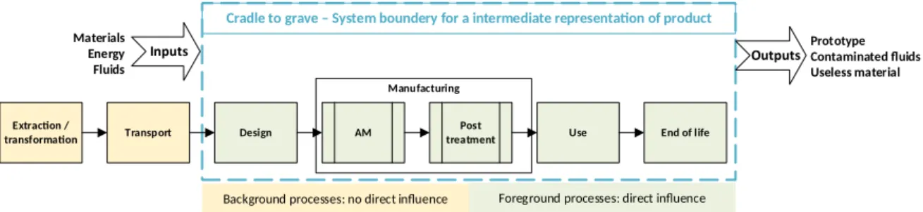
Cradle to grave – System boundery for a intermediate representation of product
Extraction /
transformation Transport
Background processes: no direct influence Foreground processes: direct influence
Prototype Contaminated fluids Useless material Materials Energy Fluids
Figure 1 Case study system boundary
The system boundary presented in Figure 1Erreur : source de la référence non trouvée follows a prototype’s LCA and consists in a study from cradle to grave. But, if the reader adopts a new product development point of view, the system boundary can also be considered as a gate to gate analysis focused on the design stage of this new product lifecycle.
In the considered system boundary (cradle to grave), the manufacturing stage, that starts with the use of AM machine and finishes after the removal of the support structure is the most influential stage as explained by Da Silva Barros et al. (2017). Concerning the design stage, even if the influence of the computer use time (CAD/TO) on the environmental impact “can make a real difference” (K Da Silva Barros & P Zwolinski, 2016) it is the same for all the tests in this study. Indeed, since a functional unit is a prototype, time spent to design is the same regardless of the AM machine used to produce it. Moreover, as the functional unit (i.e. the prototype) is used for a product feature assessment, the use stage in the considered system boundary and the end of life one may directly influence the LCA but are the same for all prototypes of the case study and also do not depend on how they are manufactured.
Life-cycle inventory
To achieve a life-cycle inventory, Le Bourhis, Kerbrat, Hascoet, and Mognol (2013) suggest considering “all the products which contribute to the environmental impact”, i.e. flows of material, fluids and energy. Thus, the upcoming flows of this study are:
the material flows. They consist of the model and support material (if available) as inputs. The produced part, the material loss due to the purge and the removed support consist in outputs.
the fluid flows. they are divided into two categories: water and liquid solving agent as inputs, soiled fluids as outputs
the energy flow. It is the electrical consumption of each manufacturing machine used during the case study (AM and post treatment). It is measured with a wattmeter (Otio CC-5000) plugged into the power jack, whose measuring range goes from 5 to 3680W, with a 1/100 precision.
Experimental equipment
Among standards (F2792-12a, 2012; ISO, 2015), AM processes can be divided into seven different categories. However, if nowadays, these categories of AM processes can be used for the direct production of models, prototypes, end use parts, and assemblies, as well as fixtures, patterns, and tooling for indirect production” (Thompson et al., 2016), only processes suitable for modeling and prototyping activities during EDS are considered in this case study. Kruth, Leu, and Nakagawa (1998) defined 5 “most successful industrial […] systems” for prototyping that belong to different AM process categories:
- Stereolithography (vat photopolymerization process),
- Fused Deposition Modeling -FDM- (material extrusion process), - Laminated Object Manufacturing (sheet lamination process), - Selective Laser Sintering (powder bed fusion)
- Ink Jet Printing – (Material Jetting -MJ- process)
Thus, to comply with this AM systems perimeter, authors considered during this case study two processes and four machines which are presented below. Three of them are classified as “professional-grade AM systems” and one as “personal system” (Wohlers 2014). Even if the global steps of a building process on AM exist, each technology has its own implementation (Gibson et al., 2015) and its own parameters, resulting in a huge amount of configurations (Conner et al., 2014) that can modify the resources consumption of a machine. In this article, the possibility to change parameters on a machine is called “openness” by the authors.
Stratasys Objet260 Connex2 and Power Blast
The Objet260 Connex2 by Stratasys is a machine working on the MJ process: produced parts are solid and can be filled with model or support material. At the end of the manufacturing, the support structure is removed with a water jet on the Power Blast machine form Balco. This post treatment machine does not offer the possibility to adjust the flow thus, water consumption only depends on the time used to remove the support structure. Due to the high price of prototypes manufactured with the Objet260 Connex2, and the use-case dimensions, the authors have chosen in a first approach to use a 1:3 reference scale and a single material manufacturing in allow comparison with the other machines.
3DSystems ProJet 3510SD and FP 1100-10
The ProJet 3510SD from 3D Systems is also based on MJ. Several differences exist between the ProJet 3510SD and the Objet260 Connex2:
- the latter can only use one model material at the time.
- the kinematics is simpler: the platform moves along the x axis, carrying out a full movement before returning to its start position, while the printing head only moves vertically.
- The openness of the machine is limited, and few manufacturing strategies are available: no possibility to change the infill percentage, the infill type or even the layer height.
The support material is a wax with a melting point of 70 ° C. The authors used, for removing this wax, a Borel FP1100-10 oven, usually dedicated for heat treatment. Its
only modifiable parameter is the temperature. For a final surface treatment, the prototypes are immersed for 50 minutes at 80°C in a vegetal oil bath.
Stratasys Dimension Elite and SCA 1200HT
The Dimension Elite by Stratasys belongs to the material extrusion processes, and more precisely on the FDM technology. Two extruders are on a unique head which is movable and can reach every corner of the building platform: one extruder is dedicated to the model material, the other for the support structure. As for FDM machines, it is possible to modify the infill percentage, so that parts can be manufactured with a low amount of material inside. Thus, models can be created with different mechanical characteristics. For the Dimension Elite, the support is dissolved in a pH10 basic solution. For this case study, the authors used the SCA 1200HT from PADT, a desktop system fitting most parts. The temperature of the recommended dissolving fluid is 70°C for ABS, so that there is no parameter to change on this machine.
MakerBot Replicator 5
The Replicator 5 by Makerbot, is a basic AM machine that is often used in makerspaces or fablabs. It is a one extruder FDM machine. Thus, model and support structure are manufactured with the same material. Removing the support structure is achieved manually. The Replicator 5 offers both an infill percentage and infill pattern parameter, leading to a variety of possibilities and a wide openness of the machine. It is also possible to use a raft for construction i.e. a special fundament that machine uses before starting the part building to ensure that small parts adhere to the construction platform.
Test part & manufacturing parameters
A car hinge is used as a test part for this case study. Its scale dimensions are 280mm×65mm×64mm. In a context of product redesign for an optimised for mass gain, this hinge enables to test, the influence of both manufacturing parameters and a design parameter on resources (i.e. flows) consumptions during AM prototyping. The design parameter is here the TO rate where a 0% rate correspond to the reference design (i.e. without TO). To have comparable results, each STL file (with or without TO) was created with a defined mesh size of 0.01mm.
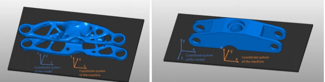
Figure 2 Test parts positioned on the building platform, reference configuration (left) and alternative configuration (right)
As a reference orientation on the platform, the longest dimension of the part was placed along the x-axis of each machine. While there is still the possibility to rotate the model along this x-axis, the authors also tested the influence of the building orientation. Figure 2 presents on the left side the topologically optimised version of the model (mass
reduction of 70%), positioned on the building platform with the reference configuration. Because the longest dimension of the model is quite long (280mm) for some of the AM machines of the study, the parts are manufactured at a reduced scale.
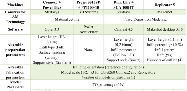
The set of studied parameters are summarized in Table 1. For each machine, the authors chose as reference parameters the default settings when the machine software is started. All parts are manufactured in an ABS-like material to ease afterwards the comparison of the environmental impact.
Machines Connex2 + Power Blas Projet 3510SD + FP1100-10 Dim. Elite + SCA 100HT Replicator 5 Constructor Stratasys 3D Systems Stratasys Makerbot
AM
Technology Material Jetting Fused Deposition Modeling Software Objet 3D ProJet
Accelerator Catalyst 4.5 Makerbot desktop 3.10
Alterable preparation
parameters
Layer height (HS-30µm) Infill type (Full) Surface finishing
(Glossy) Support style (Standard)
None
Layer height (0,254mm) Infill percentage
(Hollow LD) Support style (Smart)
Layer height (0,2mm) Infill percentage (40%) Infill pattern Raft (yes) Numbers of outline (4) Alterable fabrication parameters
Building orientation (reference configuration) Model scale (1/2; 1/3 for Objet260 Connex2 and Replicator2
Number of models on platform (1)
Model
Parameter TO percentage (0%)
Table 1 Synthesis of the parameters tested on each machine and their reference value
Results
For all measured flows, the repeatability of the four machines was controlled. It has been achieved by producing five times a same parallelepipedal part and checking that the measured values for the different flows were identical.
The material consumption (Mmaterial consumption) was collected through weighting and
compared to the software estimation of each machine. Results has shown that the estimation of material consumption given by “machine-manufacturer software” (support and model) is accurate with a calculated error lower than 2,5%. Thus, the estimated value could be used to define the best parameter configuration with a different model, as long as the longest dimension is not placed vertically on the platform. Another result is that the consumptions’ estimation changes from one machine to another: Objet260 Connex2 includes a purge in its estimation, while for the other machines the value corresponds to the material quantity needed for the part production. Therefore, all the material consumptions recorded in this case study can be generically for the four machines as follow:
Mmaterial consumption=Mmodel+Msupport+Mpurge
The electrical consumption (Eelec) is calculated by adding up the consumption of every
step of the manufacturing stage and can be decomposed thereby:
Eelec=Epreheating+EAM+Epost treatment
Because machines used for rapid prototyping in the EDS are not full-time used (compared to production ones), the authors decided to make measurements only if the
machine is cold when launching the manufacturing process. Thus, the calculation of the electrical consumption is including a preheating energy (Epreheating). Moreover, each post
treatment machine consumes a constant electrical value, obtained after a five measurements series:
0.09kWh for the Borel FP1100-10 oven 0.056kWh for the Power Blast
1,8kWh for the SCA 1200HT.
Fluid flows consumption refers to the three post-treatment (Power Blast, SCA 1200HT and Borel FP1100-10 oven) and can be generalized as follow:
Vfluids=Vwater+Voil+Vsolvingagent
For the first machine, it consists only in a 11L volume of water necessary for removing mechanically the support, for the second one it consists in a 46,5L volume of water mixed with 0,5L volume of solving agent; in the last one in a 400mL volume of vegetal oil.
From these results, the authors decided to analyze the variation of the consumptions due to the modification of each parameter compared to the reference parameters (see Table 1). The calculated difference value is then displayed in percent.
Analysis & Discussion
The process of analysing the results is the same on each machine, thus the authors decided to have first a precise look on the Objet260 Connex2, to explain how the best strategies were chosen., then to present for the three other machines the best parameters for each manufacturing strategy. The qualification criteria of each prototype selected at the end of the manufacturing are: mechanical behavior during post-processing, dimensional accuracy, surface finish. Indeed, they directly affect the prototypes’ uses such as ergonomics, shape, etc.
Objet 260 Connex2
For this machine, material and energy flows are impacted by the modification of parameters. while fluid flows consumption directly depends on the operator’s ability. Indeed, the post treatment is a manual operation; time for support removing that influences the water consumption cannot be considered as an adjustable parameter. It means that for an experimented user, water consumption is depending on the complexity and on the dimensions of the part, i.e. on design parameter. Scaling up and simplifying the prototype’s design can also be a solution to reduce it.
Influence of the parameters
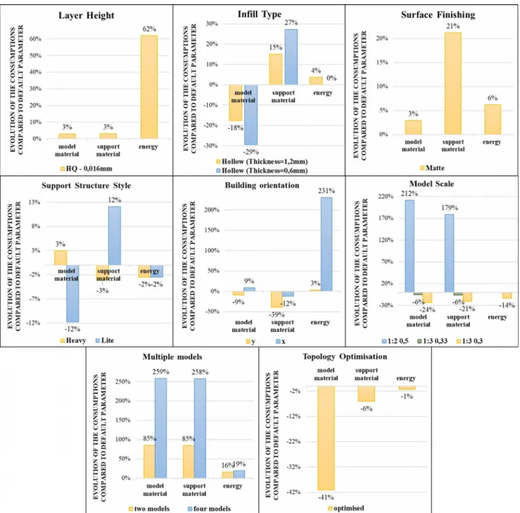
On each graph presented in Figure 3, initial consumption flow resulting from the reference parameters defines the reference line (0%). This reference configuration (see Figure 1, left) matches a model material consumption of 34 grams, with 34 grams of support material and 0.81 kWh of electrical energy consumption with a scale of 1/3 (scale 0,333 on the machine).
Figure 3 Evolution of the material and energy consumption for the different parameters and their setting value
Layer Height. As expected, modifying the layer height from 30µm (High Speed, HS)
to 16µm (High Quality, HQ) which means increasing the building resolution of the prototype, does not really affect the materials (model and support) consumption (only 3% of variation) but only the energy consumption (growth of 62%). This comes from the manufacturing time which is increased due to the increase of the sweeps’ number necessary for the part manufacturing. As an eco-manufacturing strategy, it is recommended to use the default setting (High speed 30µm) excepted if the prototype requires a high degree of finish, especially since its use is intended for example to validate ergonomics.
Infill type. The infill type influences mostly the material consumption. Choosing a
hollow infill style, compared to a full fill-in (reference setting), means that the model is fill-in with support material instead of a model material fulfilment with the default setting. Thus, the quantity of model material is reduced, but reciprocally the quantity of support material grows in nearly the same proportions. Selecting the best strategy for material saving also depends on the environmental impact of the considered materials. In this case study, the two materials (model and support) are both acrylic resins, consequently there is no benefit choosing a specific infill type for material saving, especially since energy consumption is unaffected by this change. One other point which is important to consider is the wall thickness of model material: choosing a 0.6mm value was not strong enough to enable a safe posttreatment of the part: it broke during the support removing process. It also reveals that changing this parameter to save model material cannot be a solution without considering the applied mechanical stress of the support removing or the solicitations coming from the prototype’s handling when it is for example dedicated for a working principle assessment.
Surface finishing. Selecting a matte surface finishing instead of a glossy one, increases
the support material consumption by 21% (i.e. 7 grams) and the energy consumption by 6% due to a higher manufacturing time. Indeed, to create a matte finish, the machine wraps the part in a thin layer of support material. The modification of this parameter therefore also depends on the use of the prototype such as aesthetics or ergonomics assessment. It can enable to modify the texture or the visual appearance of the part by creating a smoother or brighter surface.
Support style. Modifying the support style parameter from the reference value
(Standard) to a Heavy one is not significant for flows consumption improvement; while a Lite value enables to save 12% of model material but increases the support material consumption in the same proportions. It comes from the raft surface whose material is substitute from model material to support material. In this case study, modification the support style also does not really need to be considered.
Building orientation. Energy consumption is the main flow influenced by the building
orientation especially if the longest dimension of the model is placed along the vertical axis of the machine (Mognol, Lepicart, & Perry, 2006). Results collected in this case study confirm these findings: consumed energy increases from 0,81 kWh to 2,67 kWh, i.e. a 211% increase. Moreover, this leads to a poorer dimensional quality of the manufactured prototype: in the case study there is one-millimetre difference along the longest dimension with the default setting. The modification of the building orientation parameter is also mainly interesting for decreasing the support material consumption. Indeed, for a same building height (y and z dimensions of the tested part), the placement that fosters recesses along the z axis is the most relevant because it enables to save 39% of support material compared to the default setting.
Scale. Changing the scale of the manufactured model results in a logical linear variation
of all flows on the machine. However, it is important to notice that the machine parameter is set by a decimal number instead of a fractional one. The main risk for increasing wastes is the accuracy of the input scale value that can lead to inadequate dimensions and an unusable prototype. As an example, on the Objet260 Connex2, the user can set as entry data a value with one to 6 digits after the decimal point for a 1/3 scale (from 0.3 to 0.333333)
Multiple models build at the same time. The impact of the number of models
manufactured at the same time on the flows consumption is very informative. Indeed, as expected, building multiple models enables to save material because the purged material volume for one fabrication is allocated to a larger number of parts. More unexpectedly, the laying of the models on the platform has a significant impact on the amount of energy saved. In this study, the consumed energy increases by 16% for a manufacturing of two models placed in order to favor the filling of the y-axis (Figure 4 left) and in the same proportions for a production of four models -two models placed along the x-axis, the two others along the y-axis (Figure 4 right). The explanation comes from the operating principle of the machine: it makes a complete scan of the x-axis before moving from one step on y-axis. Thus, to minimize consumption, user must favor a maximum occupancy rate of the platform on the x-axis.
Figure 4 Tested laying for a 2 or 4 parts serial
Topology Optimisation. The use of TO to reduce the flows consumptions is justified
only if the manufacturing strategy is focused on the reduction of model material: it saves 14 grams out of 34 compared to the non-optimised part, i.e. a gain of 41%. However, the benefit of TO is not convincing for support material saving or for energy saving because these consumptions are almost unchanged. It therefore needs to take into consideration the prototype use before performing TO: material savings can be done at the expense of ergonomics assessment and the time spent by non-expert users to achieve it.
Best strategy for the Objet260 Connex2
As the results have already been analysed in the previous paragraph, the strategies on this machine are displayed in Erreur : source de la référence non trouvée. Three strategies are proposed:
reduction of the support material consumption reduction of model material consumption
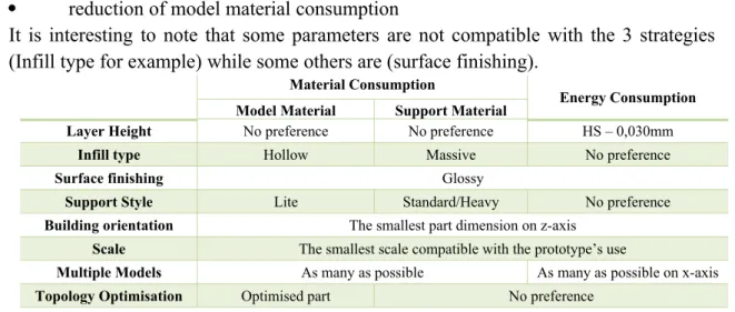
It is interesting to note that some parameters are not compatible with the 3 strategies (Infill type for example) while some others are (surface finishing).
Material Consumption
Energy Consumption Model Material Support Material
Layer Height No preference No preference HS – 0,030mm
Infill type Hollow Massive No preference
Surface finishing Glossy
Support Style Lite Standard/Heavy No preference
Building orientation The smallest part dimension on z-axis
Scale The smallest scale compatible with the prototype’s use
Multiple Models As many as possible As many as possible on x-axis
Topology Optimisation Optimised part No preference Table 2 Recommended parameters for Stratasys Objet260 Connex2
Best strategy selection from a sustainable point of view.
Using the analysis procedure described previously, the authors stated the following manufacturing parameters to be the best to reach the strategies of lowest model material consumption, lowest support material consumption and lowest electrical energy consumption on each machine.
Projet3510 SD and FP1100-10
The reference configuration on this machine has a model material consumption of 57.86 grams, with 74.55 grams of support and 8.02 kWh of electrical energy and was manufactured with the scale 1/2. The recommended parameters for each manufacturing strategy are summarized in Table 3 and come from the following conclusions:
The modification of the building orientation parameter is interesting only for decreasing the support material consumption. In the case study, the gain ranges from 31% to 50%: the first solution corresponds to part placement that allows to maximize the recesses on the z-axis and the second one to a vertical placement of the part which implies a reduced dimensional quality and a very important increase of the consumed energy during manufacturing.
Manufacturing the optimised model validates the sustainable nature of TO; an important reduction of the model and support material consumption (respectively 35 and 39%), within the same manufacturing energy consumption, are found.
As for the Connex machine, building several models placed preferentially along the x-axis of the platform at the same time becomes very interesting for an energy saving strategy. The explanation comes from the operating principle of the machine: the movement of the building platform along the x axis of the machine, does not depend on the material deposit. Moreover, material is saved because a reduction of the purge-related waste.
Material Consumption
Energy Consumption Model Material Support Material
Scale The smallest scale compatible with the prototype’s use
Multiple Models No preference As many as possible onx-axis
Topology Optimisation Optimised part
Table 3 Recommended parameters for Projet3510 SD
Dimension Elite and SCA 1200HT
The reference configuration has a model material consumption of 26.09 grams, with 13,5 grams of support and 6.67 kWh of electrical energy and was manufactured with the scale 1/2. The main results are presented in Table 4.
The modification of the layer height from the default value (0,254mm) to a smaller layer height (0,1778mm) leads to surprising results: it saves 8% of model material. Yet, as expected, the energy consumption, rises by 13% from 6,67 kWh to 7,53 kWh due to a longer time for the manufacturing. The result also suggests that choosing a higher resolution to manufacture a more accurate prototype, especially when the shape rendering is a crucial assessment criterion, can be compatible with a sustainable manufacturing.
Benefits of TO depends on the building orientation. With an optimised model placed on the reference building orientation (see Erreur : source de la référence non trouvée left), the prototype was never correctly manufactured while this error did not occur when its building orientation was the y-axis. Even if there is no explication until writing, this problem shows that changing the building orientation could lead to a useless prototype while the objective is saving model material.
Reducing the infill percentage of the model is a logical way to save model material: it has no influence on the support material consumption while the voids are not replaced by a filling with support material. However, this modification must be done sparingly to avoid weakening the prototype.
Unlike the 2 previous machines based on material jetting technology who required a purge, building multiple models at the same time is not affecting the material consumption for the Dimension Elite: duplicating a model increases twofold the material consumption but saves energy due to a single preheating for several parts.
Material Consumption Energy Consumption Model Material Support Material
Layer Height The smallest (0,1778) No preference The biggest (0,2540mm)
Infill percentage Hollow – low density No preference Hollow – low density
Support Style No preference Smart Smart/Hollow
Building orientation The smallest part
dimension on z-axis
Depends on complexity
The smallest part dimension on z-axis
Scale The smallest scale compatible with the prototype’s use
Multiple Models No preference
Topology Optimisation Optimised part Normal part No preference Table 4 Recommended parameters for Dimension Elite
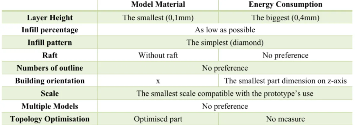
Replicator 5
The reference configuration has a model material consumption of 20.52 grams and 0.12 kWh of electrical energy and was manufactured with the scale 1/3. The authors
underline that this machine uses a unique material for the model and the support, leading to only two manufacturing strategies: model material or energy saving presented with their recommended parameters in Table 5. Furthermore, as this machine is open and offers many settings configurations, only results different from those collected on the Dimension Elite are discussed below.
As model and support are using the same material on the Replicator 5, TO proves that it is a promising parameter on this machine, when the aim is material saving, especially since the part placement on the platform does not generate manufacturing problem due to an inadequate orientation.
Beside the possibility to change the infill percentage, the Replicator 5 also offers the possibility to change the infill pattern. Two patterns “diamond” (reference value) and “hexagonal” were tested. Results show that the default setting consumes less energy due to a shorter traveling time of the extruder. Thus, modifying the infill pattern with a simpler pattern can be a strategy to reduce energy consumption.
By not using the raft, model material can be saved, but the manufactured part was too distorted as it did not adhere properly to the building platform during the fabrication. Therefore, the raft should be used if the model is slender and has a risk of non-correct adherence because it guarantees a uniform cooling of each layer and minimizes deformations.
Changing the numbers of outline, which defines the wall thickness, does not impact the flows for the used model. This parameter usually affects the mechanical properties of the model. It might have more impact if the model has another geometry and is larger, as the infill volume would increase by diminishing the numbers of outline. The most surprising result on this machine is, that manufacturing multiple models simultaneously has no impact on the model material saving strategy. This is due to the raft, manufactured for each model on the building platform. Moreover, the serial size increase modifies proportionally the energy consumption. The reason is the same as for the Dimension Elite and comes from the kinematics of the FDM machine: for a given layer, it successively builds the different outlines before moving vertically to the next layer. Thus, such a working principle multiplies all the manufacturing time and energy by the number of models to manufacture
Model Material Energy Consumption Layer Height The smallest (0,1mm) The biggest (0,4mm)
Infill percentage As low as possible
Infill pattern The simplest (diamond)
Raft Without raft No preference
Numbers of outline No preference
Building orientation x The smallest part dimension on z-axis
Scale The smallest scale compatible with the prototype’s use
Multiple Models No preference
Topology Optimisation Optimised part No measure Table 5 Recommended parameters for Replicator 5
All these results show that the sustainable manufacturing strategies (through resources saving) do not necessarily correspond to the default strategies available on the machines’ software and are not reproducible from one machine to another or from one technology to another. These settings could then enrich a database for a decision support tool whose objective would be to advise the user on the best parameters to set so that the environmental impact coming from the prototyping activities become as small as small as possible even if this user has no knowledge on AM manufacturing strategies.
Through a given prototype’s use set by the user as input data of the decision support tool, a database based on the raw data collected in this study will also link a set of features coming from this specific use with optimal settings for its manufacturing. Thus, as an example, a design team who wants to compare the ergonomic quality of concepts implicitly defines some design and manufacturing features for ergonomics tests such as the prototype’s size (i.e. a 1/1 scale), the surface finish (minimal roughness), a material with properties similar to the specifications… These features also force the setting value of manufacturing parameters such as layer height or scale. So, for a given machine and a given resources saving, it is then possible to suggest with the database the adequate setting level of all other parameters that was not previously impacted.
Even if these results can only be applied to a small panel of AM machines and for a given test-part, they prove that there is a link between the environmental impact, through the resources consumption, and the selected parameter configuration.
Conclusion and future work
The research question of this paper was: what is the influence of design and manufacturing parameters on the resources’ consumptions of AM machines and their associated support structures removing technique? Base on a case study, the authors have shown that using reference parameters instead of optimal ones impacts the consumption of model and support material as well as the energy consumption. It has also revealed that some AM technologies are advantageous when more parts are produced at the same time, especially when the user chooses to minimise the energy consumption. Concerning the use of TO, this study showed that especially for saving model material, it can be considered as a cleaner production strategy. Depending on the AM technology, the consumption of support material can be higher for the optimised part than for the normal one. Even if this result depends strongly on the used model, it highlighted that TO may not be the best eco-strategy depending on whether the model or the support material is more impacting.
This work proves that the expertise of the user of an AM machine is crucial when it comes to the environmental impact. Thus, the case study gives clear guidance on strategies how to minimise each type of consumption and will be the basis for the development a tool to give advice on how to choose the manufacturing parameters, when no expert can be consulted. Finally, the upcoming step of this study is to quantify the exact influence of the manufacturing parameters on the environmental impact, using a LCA methodology. Results will enable to choose the best machine that both minimizes the environmental impact of prototype’s manufacturing and guarantees quality, cost and manufacturing time in adequacy with the requirements.
Bibliography
Abdul Rashid, Salwa H., Evans, Stephen, & Longhurst, Philip. (2008). A comparison of four sustainable manufacturing strategies. International Journal of Sustainable
Engineering, 1(3), 214-229. doi: 10.1080/19397030802513836
Bakker, C.A. (1995). Environmental Information for Industrial Designers. Retrieved from https://repository.tudelft.nl/islandora/object/uuid:35b9dbef-3718-40fc-b64a-178b1cd0fed8?collection=research
Boujut, J-F, & Blanco, E. (2003). Intermediary Objects as a Means to Foster Co-operation in Engineering Design. Computer Supported Cooperative Work
(CSCW), 12(2), 205-219. doi: 10.1023/a:1023980212097
Brackett, D., Ashcroft, I., & Hague, R. (2011). Topology optimization for additive
manufacturing. Paper presented at the 22nd Annual international solid freeform
fabrication symposium.
Conner, Brett P., Manogharan, Guha P., Martof, Ashley N., Rodomsky, Lauren M., Rodomsky, Caitlyn M., Jordan, Dakesha C., & Limperos, James W. (2014). Making sense of 3-D printing: Creating a map of additive manufacturing products and services. Additive Manufacturing, 1-4, 64-76. doi: 10.1016/j.addma.2014.08.005
Da Silva Barros, K, & Zwolinski, P. (2016). Influence of the Use/User Profile in the LCA of 3d Printed Products. Procedia CIRP, 50, 318-323. doi: https://doi.org/10.1016/j.procir.2016.05.005
Da Silva Barros, K, Zwolinski, P, & Ikhan Mansur, A. (2017). Where do the
environmental impacts of Additive Manufacturing come from? Case study of the use of 3d-printing to print orthotic insoles. Paper presented at the 12ème
Congrès International de Génie Industriel (CIGI 2017), Compiegne, France. https://hal.archives-ouvertes.fr/hal-01525004
Da Silva Barros, Kléber, & Zwolinski, Peggy. (2016, 2016-06-15). Influence of the use/
user profile in the LCA of 3d printed products. Paper presented at the 26th CIRP
Design Conference 2016, Stockholm, Sweden.
Despeisse, Mélanie, & Ford, Simon. (2015). The Role of Additive Manufacturing in
Improving Resource Efficiency and Sustainability. Paper presented at the
Advances in Production Management Systems: Innovative Production Management Towards Sustainable Growth, Tokyo, Japan.
F2792-12a, ASTM. (2012). Standard terminology for Additive Manufacturing Technologies. West Conshohocken, PA,: ASTM International.
Gao, Wei, Zhang, Yunbo, Ramanujan, Devarajan, Ramani, Karthik, Chen, Yong, Williams, Christopher B., . . . Zavattieri, Pablo D. (2015). The status, challenges, and future of additive manufacturing in engineering. Computer-Aided Design,
69, 65-89. doi: https://doi.org/10.1016/j.cad.2015.04.001
Garetti, M, & Taisch, M. (2012). Sustainable manufacturing: trends and research challenges. Production Planning & Control, 23(2-3), 83-104. doi: 10.1080/09537287.2011.591619
Gerbert, Philipp, Lorenz, Markus, Rüßmann, Michael, Waldner, Manuela, Justus, Jan, Engel, Pascal, & Harnisch, Michael. (2015). Industry 4.0 The Future of Productivity and Growth in Manufacturing Industries: The Boston Consulting Group.
Gershenfeld, N. (2012). How to Make Almost Anything: The Digital Fabrication Revolution. Foreign Affairs, 91(6), 43-57.
Gibson, Ian, Rosen, David, & Stucker, Brent. (2015). Additive Manufacturing
Technologies. New York, NY: Springer New York.
ISO. (2006). ISO 14040:2006 - Environmental management Life cycle assessment --Principles and framework: ISO.
ISO. (2015). ISO/ASTM 52900:2015 Additive manufacturing General principles --Terminology (pp. 19).
Kruth, J.P, Leu, M.C, & Nakagawa, T. (1998). Progress in additive manufacturing and rapid prototyping. Cirp Annals, , 47(2), 525-540. doi: https://doi.org/10.1016/S0007-8506(07)63240-5
Laverne, Floriane, Segonds, Frédéric, Anwer, Nabil, & Le Coq, Marc. (2015). Assembly Based Methods to Support Product Innovation in Design for Additive Manufacturing: An Exploratory Case Study. Journal of Mechanical Design,
137(12), 121701-121701-121708. doi: 10.1115/1.4031589
Laverne, Floriane, Segonds, Frédéric, D’Antonio, Gianluca, & Coq, Marc Le. (2017). Enriching design with X through tailored additive manufacturing knowledge: a methodological proposal. International Journal on Interactive Design and
Manufacturing (IJIDeM), 11(2), 279-288. doi: 10.1007/s12008-016-0314-7
Le Bourhis, Florent, Kerbrat, Olivier, Hascoet, Jean-Yves, & Mognol, Pascal. (2013). Sustainable manufacturing: evaluation and modeling of environmental impacts in additive manufacturing. The International Journal of Advanced
Manufacturing Technology, 69(9-12), 1927-1939. doi:
10.1007/s00170-013-5151-2
Mani, M, Lyons, K.W, & Gupta, S.K. (2014). Sustainability Characterization for Additive Manufacturing. Journal of Research of the National Institute of
Standards and Technology, 119, 419-428. doi: 10.6028/jres.119.016
Markou, Foteini, Segonds, Frédéric, Rio, Maud, & Perry, Nicolas. (2017). A methodological proposal to link Design with Additive Manufacturing to environmental considerations in the Early Design Stages. International Journal
on Interactive Design and Manufacturing (IJIDeM), 11(4), 799-812. doi:
10.1007/s12008-017-0412-1
Mellor, Stephen, Hao, Liang, & Zhang, David. (2014). Additive manufacturing: A framework for implementation. International Journal of Production Economics,
149, 194-201. doi: https://doi.org/10.1016/j.ijpe.2013.07.008
Mognol, Pascal, Lepicart, Denis, & Perry, Nicolas. (2006). Rapid prototyping: energy and environment in the spotlight. Rapid Prototyping Journal, 12(1), 26-34. doi: doi:10.1108/13552540610637246
Peng, Tao, Kellens, Karel, Tang, Renzhong, Chen, Chao, & Chen, Gang. (2018). Sustainability of additive manufacturing: An overview on its energy demand and environmental impact. Additive Manufacturing, 21, 694-704. doi: https://doi.org/ 10.1016/j.addma.2018.04.022
Petrovic, Vojislav, Vicente Haro Gonzalez, Juan, Jordá Ferrando, Olga, Delgado Gordillo, Javier, Ramón Blasco Puchades, Jose, & Portolés Griñan, Luis. (2011). Additive layered manufacturing: sectors of industrial application shown through case studies. International Journal of Production Research, 49(4), 1061-1079. doi: 10.1080/00207540903479786
Prendeville, Sharon, Hartung, Grit, Brass, Clare, Purvis, Erica, & Hall, Ashley. (2017). Circular Makerspaces: the founder’s view. International Journal of Sustainable
Rio, Maud, Reyes, Tatiana, & Roucoules, Lionel. (2013). Toward proactive (eco)design process: modeling information transformations among designers activities.
Journal of Cleaner Production, 39, 105-116. doi: 10.1016/j.jclepro.2012.07.061
Smith, A., Fressoli, M., Abrol, D., Arond, E., & Ely, A. (2016). Grassroots Innovation
Movements
Stock, T, & Seliger, G. (2016). Opportunities of Sustainable Manufacturing in Industry
4.0. Procedia CIRP, 40, 536-541. doi:
https://doi.org/10.1016/j.procir.2016.01.129
Thompson, Mary Kathryn, Moroni, Giovanni, Vaneker, Tom, Fadel, Georges, Campbell, R. Ian, Gibson, Ian, . . . Martina, Filomeno. (2016). Design for Additive Manufacturing: Trends, opportunities, considerations, and constraints.
CIRP Annals - Manufacturing Technology. doi:
http://dx.doi.org/10.1016/j.cirp.2016.05.004
Worrell, Ernst, Levine, Mark, Price, Lynn, Martin, Nathan, van den Broek, Richard, & Block, Kornelis. (1997). Potentials and policy implications of energy and material efficiency improvement Lawrence Berkeley National Laboratory: United Nations.
Zegard, Tomás, & Paulino, Glaucio H. (2016). Bridging topology optimization and additive manufacturing. Structural and Multidisciplinary Optimization, 53(1), 175-192. doi: 10.1007/s00158-015-1274-4