UNIVERSITÉ DE MONTRÉAL
IMPROVEMENT OF BARRIER PROPERTIES OF
POLY(ETHYLENE TEREPHTHALATE) WITH NANOCLAY
HESAM GHASEMI
DÉPARTMENT DE GÉNIE CHIMIQUE
ÉCOLE POLYTECHNIQUE DE MONTRÉAL
THÈSE PRÉSENTÉE EN VUE DE L’OBTENTION
DU DIPLÔME DE PHILOSOPHIAE DOCTOR (Ph.D.)
(GÉNIE CHIMIQUE)
DÉCEMBRE 2010
UNIVERSITÉ DE MONTRÉAL
ÉCOLE POLYTECHNIQUE DE MONTRÉAL
Cette thèse intitulée:
IMPROVEMENT OF BARRIER PROPERTIES OF
POLY(ETHYLENE TEREPHTHALATE) WITH NANOCLAY
présentée par: GHASEMI Hesam
en vue de l’obtention de diplôme de: Philosophiae Doctor
a été dûment acceptée par le jury d’examen constitué de:
Mme HEUZEY Marie-Claude, Ph.D., présidente
M. CARREAU Pierre, Ph.D., membre et directeur de recherche
M. KAMAL Musa, Ph.D., membre et codirecteur de recherche
M. AJJI Abdellah, Ph.D., membre
ACKNOWLEDGEMENTS
I would like to offer my sincere and humble gratitude to my supervisors, Prof. Pierre Carreau and Prof. Musa Kamal. It was a great privilege to work with these wise and understanding gentlemen and I do not forget their support and the trust they placed in me in this project.
A special word of thanks is owed to Dr. Tabatabaei, Dr. Calderon, Ms. Leelapornpisit, Ms. Hamdine and last but not least, Dr. Chapleau, for their help during this study.
RÉSUMÉ
Le polyéthylène téréphtalate (PET) comme polymère d’ingénierie semi-cristallin trouve énormément d’applications dans l’industrie des emballages. Cependant, pour certaines applications comme celles des boissons gazeuses et des bières, diminuer sa perméabilité au gaz, autrement dit augmenter ses propriétés barrières, demeure un défi considérable. L’introduction de feuillets de nano-argile de silicate en tant que phase imperméable dans la matrice polymère devient ainsi une alternative intéressante. Le mélange à l’état fondu et la polymérisation in situ sont des techniques généralement utilisées pour produire des nano-composites de PET. La première méthode reste cependant préférable car elle présente des avantages économiques et environnementaux, puisqu’elle ne nécessite pas la présence de solvants ni de monomères.
Dans la première phase de la présente étude, les nano-composites de PET (NCPs) ont été préparés en utilisant différentes argiles organiquement modifiées. La compatibilité avec la matrice, ainsi que la stabilité thermique de l’ensemble, jouent un rôle prépondérant dans l’évolution morphologique des NCPs.
Dans la deuxième phase, des films minces de NCP ont été produits avec succès par extrusion suivi d’un étirage. L’effet de l’incorporation des argiles sur les propriétés mécaniques, barrières, thermiques et optiques des produits finaux a été étudié. Aussi, l’importance de la cristallinité lors de la solidification en sortie d’extrusion et l’influence de la présence des argiles sur le degré de cristallinité en conditions isothermes comme non-isothermes ont été investiguées.
ABSTRACT
Polyethylene terephthalate (PET), as a semi crystalline engineering polymer, is used extensively in packaging applications. However, gas permeability is a challenge in some applications such as soft drinks and beers. The introduction of layered silicate nanoclay, as an impermeable nanoparticle phase in a polymer matrix, is an attractive approach to enhance gas barrier properties. Melt compounding and in situ polymerization are the main techniques employed to produce PET nanocomposites. The former is the preferred method for preparation of polymer nanocomposites, which has environmental and cost advantages, due to the absence of solvents and monomers.
In the first phase of this work, PET clay nanocomposites (PCN) were prepared using different types of organo-modified clay, including ammonium, phosphonium and imidazolium surfactants. Both compatibility and thermal stability play an important role in morphological development of PCNs.
In the second and main part of this project, PCN thin films were prepared successfully, using cast film extrusion. The effect of incorporated clay on mechanical, barrier, thermal and optical properties of the products was studied. Incorporating 3 wt% Cloisite30B into PET matrix, led to 23% reduction in oxygen permeability and 20% improvement in tensile modulus. The effect of processing conditions, including screw profile, screw speed and feeding rate, on properties of PCN films were also studied. It was found that screw speed and, accordingly, applied shear has stronger effect on barrier and mechanical properties of the final products than feeding rate (residence time). At the highest screw speed, 27% and 30% improvement in barrier properties and tensile modulus were achieved, respectively.
crystallization behavior have an important effect on the mechanical, optical and barrier properties of the nanocomposites. Thus, both non-isothermal and isothermal crystallization kinetics of PCN were investigated. It was found that, overall, isothermal crystallization of PET was faster in the PCNs than in the neat PET. However, the presence of clay leads to less perfect crystalline structures. The calculated effective crystallization activation energy for the PCNs was higher than for the PET, which suggests smaller crystalline structure for the PCNs during non-isothermal crystallization.
CONDENSÉ EN FRANÇAIS
Des problèmes de stabilité thermique des nano-composites sont souvent rencontrés lorsqu’on procède à haute température au mélange du PET avec des nano-argiles organiques. Cette dégradation thermique touche autant le PET, les argiles organiquement modifiées que la compatibilité entre le PET et l’agent de modification chimique. En début de cette étude, différentes argiles modifiées par des agents de surface à base d’ammonium, de phosphonium et d’imidazolium ont été testées. Nous avons trouvé que l’argile commerciale à base d’ammonium, la Cloisite 30B (C30B) donnait le meilleur degré de séparation des feuillets d’argile et par conséquence la meilleure morphologie. En effet, la microscopie à balayage électronique (SEM) a révélé une bonne distribution des argiles et la microscopie électronique par transmission (TEM) a confirmé l’existence de tactoïdes ainsi que de feuillets individuels. Cependant, la C30B s’est avérée être la moins stable thermiquement des argiles modifiées testées. En effet, même si les deux groupements hydroxyles existant au sein de la C30B peuvent accroître la compatibilité entre les chaînes de PET et l’argile organique, ils sont néanmoins suspectés de causer la dégradation thermique de l’agent de surface à la température de mélange. Les amas de tactoïdes observés dans le cas de la C30B sont probablement le résultat d’un mélange insuffisant et/ou de l’affaissement brusque des feuillets de silicate dû à la dégradation thermique de l’agent de surface à la température de mélange. En revanche, la TGA a bien montré que la stabilité thermique dans le cas des argiles à base d’imidazolium et de pyridinium était meilleure que celle de la C30B; cependant leurs températures à 5 % de réduction massique (T5%) sont proches de la température
de procédé; les liens vinyles et C=C contribuent similairement à la dégradation de l’agent modifiant. Le manque de compatibilité entre les chaînes de PET et le surfactant à base d’imidazolium pourrait expliquer la présence des tactoïdes dans le système. Mise à part
l’amélioration de la stabilité thermique, le faible degré de dispersion des feuillets d’argile constitue une grande limite pour ce type d’argile en comparaison à la C30B.
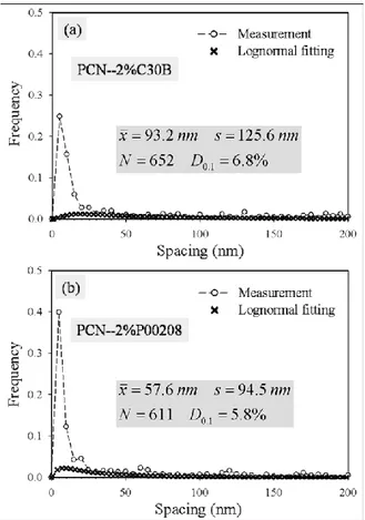
Dans un souci d’amélioration de la stabilité thermique, quelques surfactants à base de phosphonium (P00408, P00308 and P00208) ont également été examinés. Ces composés ainsi que leurs argiles organiques correspondantes ont montré certes une amélioration de la résistance à la dégradation thermique à la température de mélange du PET, mais la compatibilité entre eux et le PET reste une limite critique. Ainsi, les nano-composites en résultant contenaient plus de tactoïdes et d’amas dans leurs structures. Plusieurs facteurs pourraient expliquer cela, entre autres la faible diffusivité du PET dans l’espace confiné entre les feuillets de silicate et possiblement le besoin d’utiliser un mélange plus intensif. Apparemment, le petit groupement alkyle et le groupement rigide phényle dans les P00308 et P00408 respectivement, produisent une compacité plus élevée de l’agent modifiant entre les feuillets de silicate. L’alignement, l’arrangement confiné et latéral de l’agent modifiant pourrait constituer un obstacle à la diffusion des chaînes polymères dans l’espace existant entre les feuillets de silicate. Les chaînes de PET ont du mal à pénétrer dans les galeries, dû à la saturation de l’espace par la présence des molécules du surfactant. En comparaison aux deux premiers surfactants à base de phosphonium, le P00208 a une longue queue aliphatique qui fournit plus de sites d’interaction avec le polymère, à la surface de l’argile. Les résultats statistiques montrent que le parcours libre D0.1, des nano-composites
avec le P00208 est 5.8%, ce qui représente 1% de moins que celui des nano-composites avec la C30B.
Pour produire des nano-composites par extrusion à l’état fondu, les agrégats d’argile et les tactoïdes doivent être réduits en dimension. Les chaînes de polymères doivent par la suite pénétrer dans l’espace des galeries. Un poids moléculaire élevé et de longues chaînes polymères contribuent à un cisaillement plus intense durant le mélange, tandis qu’un poids moléculaire bas
et de courtes chaînes polymériques facilitent leur pénétration dans les galeries de l’argile. La deuxième phase de cette étude a été donc consacrée à l’amélioration de la mise en œuvre des nano-composites. Pour ce faire, un grade expérimental de PET de haute viscosité et un autre de plus faible viscosité et d’usage général ont été mélangés selon le ratio 4:1 (faible : haute viscosité). Puisque parmi les autres argiles organiquement modifiées, la C30B a montré la meilleure morphologie, des films minces de PET contenant 3% massique de C30B ont été préparés par extrusion suivi d’un étirage-calandrage). Les études morphologiques incluant l’observation directe par TEM et la diffraction des rayons X à angle large en deux dimensions (2D-WAXD) ont révélé que les feuillets de silicate ont été orientés dans la direction de l’écoulement. L’augmentation du taux d’étirage ne semble pas avoir d’effet sur leur degré d’orientation.
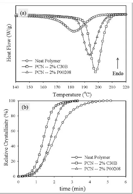
Les résultats de DSC ont montré une basse température de cristallisation pour les films de nano-composites, indiquant ainsi que les argiles agissent comme des sites de nucléation durant la cristallisation. Ainsi la présence de plusieurs sites de nucléation conduit à une cristallisation plus rapide et à l’augmentation de la cristallinité induite durant l’extrusion d’un facteur de 2 en incorporant 3% massique de C30B par exemple. Le degré de cristallinité a également été augmenté d’un facteur de 4 lors du recuit des films à 150°C. La présence de l’argile et leur exfoliation incomplète réduisent, comme attendu, la clarté des films et augmentent leur opacité. Comme les valeurs mesurées de l’opacité et de la clarté pour les nano-composites étaient moins de 6% et plus de 85% respectivement, la transparence des films selon la norme ASTM D1003, peut être considérée comme acceptable.
Les valeurs de perméabilité à l’oxygène ont montré que le taux d’étirage n’a pas d’effet signifiant sur les propriétés barrières des films produits. À la concentration de 3% massique de C30B, une réduction de perméabilité à l’oxygène de 23% a été obtenue. La perméabilité à
l’oxygène pour du PET pur et des films de nano-composites recuits décroit de 40 et 46% respectivement. Cela indique qu’en plus de la tortuosité, on devrait prendre en compte l’immobilité des segments de chaînes polymères due à un environnement confiné. Après recuit, les lamelles cristallines induisent plus de confinement et d’obstacles au sein de la matrice conduisant ainsi à une mobilité moindre des chaînes et à une perméabilité plus réduite. En d’autres termes, au même titre que l’effet des feuillets de silicate, la faible perméabilité de la phase cristalline comparée à la phase amorphe pourrait constituer une approche complémentaire pour réduire la perméabilité au gaz.
La C30B contient 30% de surfactant organique, ce qui veut dire que les nano-composites ayant une concentration massique nominale de 3% de C30B devraient contenir 2.1% massique en teneur en cendres. Hors la teneur en cendres réelle mesurée a été 1.8%; cette différence est probablement due à la perte d’une certaine quantité d’argile dans la trémie d’alimentation de l’extrudeuse. Cette teneur correspond à la fraction volumique de feuilles de silicate de =0.009 dans les nano-composites. En se basant sur la perméabilité seuil de percolation reportée et sur la valeur prédite par des modèles de normalisation, le rapport de forme (α) des feuilles de silicate est 150. Les prédictions des modèles de Nielson (analytique) et de Gusev (numérique) ont été proches de nos valeurs expérimentales. On doit mentionner ici que ces modèles assument que la structure est entièrement dispersée et orientée. Comme la morphologie des films nano-composites a bien montré une structure partiellement intercalée, la différence existant entre la prédiction de ces modèles et la perméabilité relative (K=0.77) mesurée expérimentalement est acceptable. Concernant les valeurs prédites par ces modèles, on peut conclure que même dans le cas d’une exfoliation complète, la perméabilité devrait au mieux la moitié de la valeur du PET pur à ce niveau de charge d’argile (=0.009). Les micrographes de TEM ont été utilisés pour estimer le
rapport de forme moyen α, qui n’est autre que le rapport entre la longueur (l) et l’épaisseur (t) des particules d’argile. L’histogramme d’analyse d’images basé sur ~200 ratios calculés a donné un rapport de forme moyen des particules de silicate de 47. En tenant compte de la perméabilité relative expérimentale (K=0.77) dans le calcul par les modèles de Nielson (analytique) et de Gusev (numérique), on trouve que les rapports de forme sont 63 et 55 respectivement, ce qui est en cohérence avec la valeur donnée par l’analyse d’images.
En présence d’argile, la résistance à la déchirure décroit dans la direction de la machine (MD) et la direction transversale (TD). Quant à la propagation de la déchirure, elle est légèrement plus importante dans TD que dans MD, cela pourrait être dû à une orientation partielle des chaînes de PET dans la direction de l’écoulement. Par rapport aux films de PET pur, l’incorporation des argiles mène à une augmentation du module d’élasticité en traction et de leur fragilité. En effet, à 3% massique de C30B, le module d’élasticité de traction augmente d’environ 20%. Comme la morphologie des nano-composites indiquait la coexistence d’une structure intercalée et de tactoïdes dispersés, il s’avère qu’elle a un effet signifiant sur le renforcement mécanique. Une pile de feuillets d’argile comprenant le surfactant organique ou les chaînes de polymère entre les couches d’argile peut être considérée comme une pseudo-particule ayant un plus faible rapport de forme effectif et une fraction volumique plus élevée.
Pour étudier l’effet des conditions de procédé sur les propriétés des produits finaux, deux géométries de vis avec des éléments de mélange différents tournant à différentes vitesses (N) et différents taux d’alimentation (Q) ont été utilisés pour préparer des films de nano-composites de PET/argile (PCN) contenant 3% massique de C30B. Les patrons de XRD ont indiqué que la distance intercalaire entre les feuillets d’argile était indépendante des conditions utilisées; par contre la caractérisation macroscopique incluant les propriétés barrières et mécaniques ont bien
montré que le niveau de délamination des feuillets a été affecté.
En se basant sur l’observation directe au TEM, on peut conclure qu’à haute vitesse de rotation de la vis (haute déformation) ou à faible taux d’alimentation (temps de séjour plus élevé), une morphologie partiellement exfoliée/intercalée peut être obtenue. Pour mettre en évidence l’effet de la géométrie de la vis sur le degré de dispersion des feuillets d’argile, la distance du parcours libre entre particules a été utilisée pour estimer le degré de dispersion dans des échantillons préparés à hautes vitesses de vis. Il semblerait que l’utilisation d’éléments de malaxage larges suivis d’éléments de mélange étroits donnerait une meilleure délamination. Il est bon de mentionner ici qu’à la plus haute vitesse de rotation de vis (N=250 rpm) le couple mesuré pour la 2ème géométrie de vis était 10% plus important que pour la 1ère.
Les mesures de DSC ont montré qu’aux mêmes conditions de procédé, les films de PCN ont une température de cristallisation plus basse Tc, (~ 9 °C) que les films de PET pur. Quelque soit
la géométrie de vis la Tc des échantillons préparés à la plus basse vitesse (N=150 rpm) était un
peu plus élevée que celle des échantillons préparés à plus haute vitesse (N=250 rpm). La différence était cependant plus nette en utilisant une vitesse de vis constante et un taux d’alimentation le plus élevé; les échantillons ont en effet montré une réduction de Tc de 2-3 °C.
On peut conclure, dans ce cas, que ces échantillons ont plus de sites de nucléation que les autres. Il est aussi probable que la dégradation du PET en présence de la C30B soit plus importante et la réduction du poids moléculaire contribue à la réduction de Tc. Ceci dit, une faible valeur de Tc
pourrait être reliée à une meilleure délamination des feuillets d’argile ou à la dégradation de la matrice et, par conséquence, la présence de courtes chaînes de polymère due au temps de séjour long à faible taux d’alimentation. Ceci était également en concordance avec les propriétés mécaniques.
la géométrie de vis utilisée. À une certaine vitesse de rotation de vis et un certain taux d’alimentation de l’extrudeuse, les valeurs de K étaient assez proches. Cependant pour un même échantillon la vitesse de vis semble avoir un effet plus important que le taux d’alimentation de l’extrudeuse.
Par rapport aux films de PET pur, l’incorporation de l’argile mène à une augmentation du module d’élasticité en traction. Pour toutes les conditions de procédé, les films de PCN préparés avec le 2ème géométrie de vis ont montré une légère augmentation (3-4%) du module d’élasticité en traction, ceci pourrait être attribué à une meilleure distribution de l’argile dans la matrice comme discuté plus haut par l’observation directe par TEM et en se basant sur les valeurs de D0.1.
Pour une géométrie de vis, une augmentation plus importante du module a été obtenue à la vitesse maximale de vis : 26 et 30% pour les échantillons M4 et W4 respectivement. Malgré cette augmentation, il semblerait qu’au taux d’alimentation le plus faible (un temps de séjour plus long) provoquerait une dégradation plus importante de la matrice. Et pour un taux d’alimentation constant, le module d’élasticité en traction semble augmenter graduellement avec la vitesse de vis.
En se basant sur l’effet du traitement thermique (recuit) sur les propriétés barrières des films de PCN et l’effet de l’argile sur la cristallinité du polymère, la cinétique de cristallisation isotherme et non isotherme a été également étudiée. Afin d’évaluer les paramètres de cristallisation, nous nous sommes concentrés uniquement sur les échantillons contenant 1% massique se C30B. La théorie de Avrami montre que la cristallisation isotherme des nano-composites prend place plus rapidement. Une analyse plus poussée utilisant le traitement de Lauritzen-Hoffman a révélé que la présence de l’argile mène à une structure cristalline moins parfaite. En d’autres termes, par rapport au PET pur, le point de fusion à l’équilibre des PCN apparait à plus haute température et le travail nécessaire au repli des chaînes polymères en
présence de l’argile est légèrement plus élevé. La DSC modulée (MDSC) a été utilisée pour mettre plus de lumière sur les multiples endothermes de fusion observées lors du chauffage des échantillons cristallisés isothermiquement. Il apparait que le troisième pic endotherme observé soit attribué à la recristallisation et à la fusion des cristaux organisés durant le chauffage, tandis que les premier et deuxième pics sont associés à la fusion des cristaux primaires et secondaires respectivement. L’équation modifiée d’Avrami et la méthode combinée de Avrami-Ozawa ont également été appliquées pour décrire le processus de cristallisation non isotherme. L’énergie barrière effective calculée pour les nano-composites était plus importante que le PET pur, ce qui indique une structure cristalline moins parfaite pour les nano-composites lors de la cristallisation non isotherme.
TABLE OF CONTENT
ACKNOWLEDGEMENTS ... iii
RÉSUMÉ ... iv
ABSTRACT ... v
CONDENSÉ EN FRANÇAIS ... vii
TABLE OF CONTENT ... xv
LIST OF TABLES ... xix
LIST OF FIGURES ... xxi
CHAPTER 1 ... 1
INTRODUCTION ... 1
CHAPTER 2 ... 3
LITERATURE REVIEW ... 3
2.1 Reduction of permeability in PET ... 3
2.2 Preparation of PET nanocomposites ... 9
2.3 Characterization of PCN as a final product ... 12
2.4 Effect of nanoclay on crystallization behavior of PCN ... 13
2.5 Objectives ... 15 CHAPTER 3 ... 16 METHODOLOGY ... 16 3.1 Materials ... 16 3.1.1 PET ... 16 3.2.2. Organomodified Clays ... 17 3.2 Process ... 18
3.3. Characterization ... 21 3.3.1 Morphology ... 21 3.3.2 Thermal Properties ... 22 3.3.3 Optical Properties ... 24 3.3.4 Barrier Properties ... 25 3.3.5 Mechanical Properties ... 25 CHAPTER 4 ... 27 ORGANIZATION OF ARTICLES ... 27 CHAPTER 5 ... 30
Preparation and characterization of PET/Clay nanocomposites by melt compounding ... 30
5.1 Introduction ... 31
5.2 Experimental ... 33
5.2.1 Materials ... 33
5.2.2 Melt Compounding ... 34
5.2.3 Characterization ... 36
5.3 Results and discussion ... 37
5.3.1 Ammonium surfactant ... 37 5.3.2 Imidazolium surfactants ... 41 5.3.3 Phosphonium surfactants ... 43 5.4 Conclusion ... 49 5.5 Acknowledgments ... 50 5.6 References ... 50 CHAPTER 6 ... 53
6.1 Introduction ... 54
6.2 Experimental ... 55
6.2.1 Materials ... 55
6.2.2 Melt Compounding ... 56
6.2.3 Characterization ... 57
6.3 Results and discussion ... 59
6.3.1 Morphology ... 59 6.3.2 Crystallization Behavior ... 62 6.3.3 Optical Properties ... 65 6.3.4 Oxygen Permeability ... 66 6.3.5 Mechanical Properties ... 72 6.4 Conclusion ... 75 6.5 Acknowledgments ... 75 6.6 References ... 76 CHAPTER 7 ... 79
Effect of processing conditions on properties of PET/clay nanocomposite films ... 79
7.1 Introduction ... 80
7.2 Experimental ... 82
7.2.1 Materials ... 82
7.2.2 Melt Compounding ... 82
7.2.3 Characterization ... 86
7.3 Results and discussion ... 87
7.3.1 Morphology ... 87
7.3.3 Oxygen Permeability ... 96 7.3.4 Mechanical Properties ... 98 7.4 Conclusion ... 100 7.5 Acknowledgments ... 101 7.6 References ... 102 CHAPTER 8 ... 107 GENERAL DISCUSSION ... 107 CHAPTER 9 ... 112
CONCLUSIONS AND RECOMMENDATIONS... 112
9.1 Conclusions ... 112
9.2 Originality of the work ... 115
9.3 Recommendations ... 116
REFERENCES ... 118
Appendix A ... 130
LIST OF TABLES
Chapter 3Table 3.1: The characteristics of the organically-modified clays ... 17
Chapter 5 Table 5.1: Characteristics of the neat polymer and organically-modified clays ... 34
Table 5.2: TGA and XRD results of PCNs ... 38
Table 5.3: Form factors of phosphonium-modified clays ... 44
Table 5.4: DSC results of PCNs with C30B and P00208 ... 49
Chapter 6 Table 6.1: Predicted relative permeability values for different models. (=0.009 & α=150) ... 71
Table 6.2: Halpin-Tsai and Pseudoinclusion models ... 74
Chapter 7 Table 7.1: Processing conditions and sample identifications ... 85
Appendix A Table A.1: Triple melting points of the PET and PCNs versus isothermal crystallization, T, obtained by DSC. ... 137
Table A.2: Total released heat and results of the Avrami analysis for isothermal crystallization of the PET and PCNs. All tests were done twice and the average values of ΔH are reported, here. ... 140
Table A.3: The results of Malkin analysis for isothermal crystallization of the PET and PCNs ... 145
Table A.4: Results of Lauritzen-Hoffman analysis for isothermal crystallization of PET and PCNs ... 146
Table A.5: Characteristic data of non-isothermal crystallization of the PET and PCNs. All tests were done twice and the average values of ΔH are reported, here. ... 149 Table A.6: Results of the Avrami analysis for non-isothermal crystallization of the PET and
PCNs ... 153 Table A.7: Results of the combined Avrami and Ozawa kinetic models for non-isothermal
crystallization of the PET and PCNs ... 154 Table A.8: Crystallization rate coefficient, crystallization rate parameter and crystallization
LIST OF FIGURES
Chapter 2Figure 2.1: Schematic of barrier mechanism of PET/PEN blends: a) before and b) after biaxial deformation [11] ... 5 Figure 2.2: Pictorial effect of silicate layers on permeation of small molecules ... 9 Figure 2.3: Common procedure for preparing PET nanocomposites by in situ
polymerization: a) modification of clay and b) intercalation by polymerization... 10 Chapter 3
Figure 3.1: Experimental strategy ... 16 Figure 3.2: Screw configuration: a) 1st mixing zone with 30, 60 and 90° elliptical elements;
b) 2nd mixing zone with 30° elliptical elements; c) 3rd mixing zone with 60° elliptical elements ... 18 Figure 3.3: Screw configuration: a) 1st mixing zone composed of both 45° right and left
hand kneading blocks; b) 2nd mixing zone with 45° right hand kneading blocks; and c) 3rd mixing zone including 45° and 90° kneading blocks. KB and LH denote kneading block and left hand, respectively. The first two numbers indicate the staggering angle and number of blocks, respectively and the third one represents the length in mm. ... 19 Figure 3.4: First screw profile: a) 1st mixing zone composed of 10 kneading elements with
both positive (right hand) and negative (left hand) 60° staggering angle; b) 2nd mixing zone with two left and right hand ZME elements; and c) 3rd mixing zone including kneading elements with positive 60° staggering angle. ... 20 Figure 3.5: Second screw profile: a) 1st mixing zone composed of three wide kneading
elements with 90° staggering angle followed by two narrow kneading blocks with 30° and 60° staggering angle; b) 2nd mixing zone with three kneading elements (0°) followed by 8 kneading elements with both positive (right hand) and negative (left hand) 60° staggering angle; and c) 3rd mixing zone including three wide kneading elements with 90° followed by 10 kneading elements with 30° and 60° staggering angle. ... 21 Chapter 5
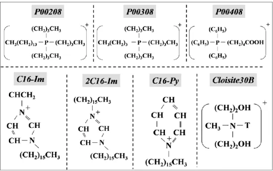
Figure 5.1: Chemical structure of the surfactants. The negatively charged counter-ions are chlorine or bromine ... 35 Figure 5.2: Screw configuration: a) 1st mixing zone with 30, 60 and 90° elliptical elements;
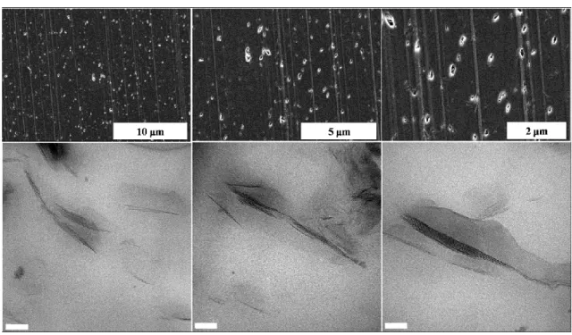
b) 2nd mixing zone with 30° elliptical elements; c) 3rd mixing zone with 60° elliptical elements ... 36 Figure 5.3: SEM images of the PCN with 2 wt% C30B ... 38 Figure 5.4: TEM images of the PCN with 2 wt% C30B (All scale bars represent 50 nm) ... 39 Figure 5.5: Various intercalation mechanisms for the PNC containing 2 wt% C30B. The
main micrograph shows the break-up and inset depicts peeling. ... 40 Figure 5.6: Layer spacing histogram of: a) the PCN with 2 wt%C30B; and b) the PCN with
2 wt%P00208 ... 41 Figure 5.7: Morphology of the PCN containing 1.25 wt% 2C16-Im a) SEM; and b) TEM
(All scale bars in TEM micrographs represent 50 nm) ... 42 Figure 5.8: SEM images of the PCN containing 2 wt% P00408 ... 43 Figure 5.9: SEM images of the PCN containing 2 wt% P00308 ... 44 Figure 5.11: SEM images of the PCN containing 2 wt% P00208 ... 45 Figure 5.11: TEM images of the PCN with 2 wt% P00208 ... 46
Figure 5.12: DSC results of the PCNs with C30B prepared by TSE, at 10°C/min a) Cooling cycle (2nd cycle); and b) Relative crystallinity vs. time ... 48 Chapter 6
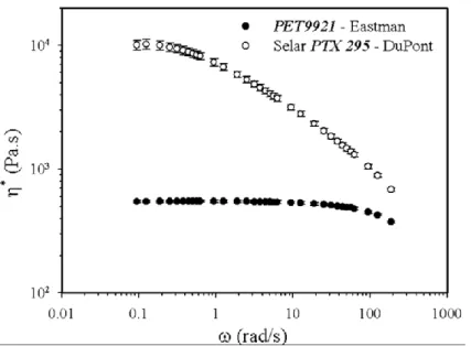
Figure 6.1: Complex viscosity of the neat polymers measured with a CSM rheometer at a stress amplitude of 200 Pa and 280 °C ... 56 Figure 6.2: Screw configuration: a) 1st mixing zone composed of both 45° right and left
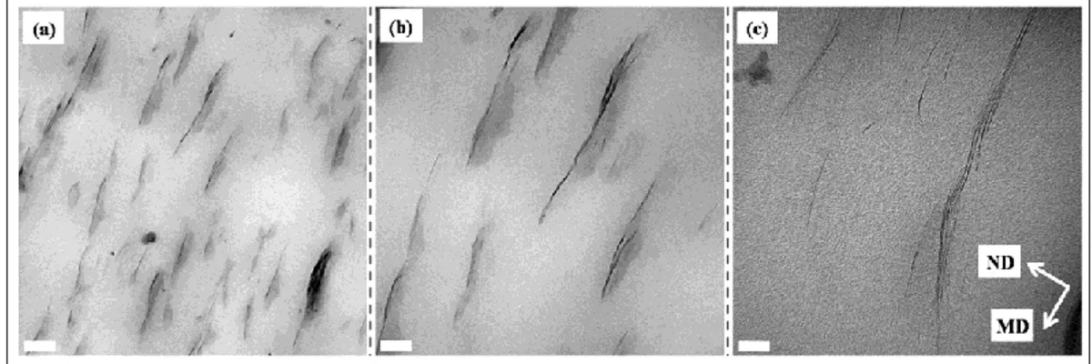
hand kneading blocks; b) 2nd mixing zone with 45° right hand kneading blocks; and c) 3rd mixing zone including 45° and 90° kneading blocks. KB and LH denote kneading block and left hand, respectively. The first two numbers indicate the staggering angle and number of blocks, respectively and the third one represents the length in mm. ... 57 Figure 6.3: TEM micrographs of PCN films containing 3% C30B at the largest draw ratio
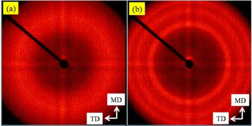
(65) MD and ND denote machine and normal direction, respectively. The scale bars represent a) 0.2 µm; b) 100 nm; and c) 20 nm. ... 60 Figure 6.4: 2-D WAXD patterns of PCN films containing 1% C30B at the largest draw
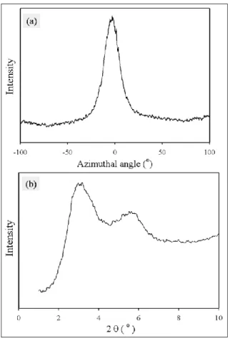
ratio (65) in: a) MN; and b) MT plane The insert depicts the observed planes. ... 60 Figure 6.5: a) Azimuthal intensity profile; and b) Diffraction spectrum of PCN films with
1% C30B at the largest draw ratio (65) in MN plane ... 61 Figure 6.6: Azimuthal intensity profiles of PCN films containing 1% C30B at a) the
smallest (25); and b) largest (65) draw ratios in MN plane ... 62 Figure 6.7: DSC results of PCN films with C30B. a) DSC traces during cold crystallization;
b) DSC of annealed films; c) melting points of annealed samples vs. clay content; d) crystallinity before and after annealing ... 63 Figure 6.8: 2-D WAXD patterns of PCN films with 3%C30B at the largest draw ratio (65).
a) before; and b) after annealing... 64 Figure 6.9: Diffraction spectrum of PCN films after annealing: a) neat PET; and b) PCN
with 3% C30B ... 65 Figure 6.10: Haze and clarity of PCN films with C30B at the largest draw ratio (65) ... 66 Figure 6.11: a) Oxygen permeability of PCN films vs. draw ratio; and b) Effect of
crystallization on barrier properties of PCN films with C30B at the largest draw ratio (65) ... 68 Figure 6.12: Measuring the aspect ratio of the silicate layers by image analysis. Silicate
layers are laid in MD ... 70 Figure 6.13: Histogram of calculated aspect ratio for PCN films with 3%C30B ... 72 Figure 6.14: Tear resistance of PCN films in the machine (MD) and transverse (TD)
directions at the largest draw ratio (65) ... 73 Figure 6.15: Tensile modulus in MD and puncture resistance of PCN films at the largest
draw ratio (65) ... 73 Chapter 7
Figure 7.1: Complex viscosity of the neat polymers measured with a CSM rheometer at a stress amplitude of 200 Pa and 280 °C ... 82 Figure 7.2: First screw profile: a) 1st mixing zone composed of 10 kneading elements with
both positive (right hand) and negative (left hand) 60° staggering angle; b) 2nd mixing zone with two left and right hand ZME elements; and c) 3rd mixing zone including kneading elements with positive 60° staggering angle. ... 83 Figure 7.3: Second screw profile: a) 1st mixing zone composed of three wide kneading
elements with 90° staggering angle followed by two narrow kneading blocks with 30° and 60° staggering angle; b) 2nd mixing zone with three kneading
elements (0°) followed by 8 kneading elements with both positive (right hand) and negative (left hand) 60° staggering angle; and c) 3rd mixing zone including three wide kneading elements with 90° followed by 10 kneading elements with 30° and 60° staggering angle. ... 84 Figure 7.4: WAXD spectra of: a) PCN films prepared using the first screw profile (M
series); b) PCN films prepared using the second screw configuration (W series); c): samples M2 and M4 (constant feeding rate, first screw profile); d) samples W2 and W4 (constant feeding rate, second screw profile); e) samples M5 and M6 (constant screw speed, first screw profile); and f) samples W5 and W6 (constant screw speed, second screw profile) ... 88 Figure 7.5: Top) Typical 2-D WAXD patterns of PCN films in a) MN; and b) MT plane;
Bottom) Diffraction spectrum of PCN films prepared using the first screw profile at c) constant feeding rate; and d) constant screw speed. MD, TD and ND in the insert, represent machine, transverse and normal directions, respectively. Accordingly, the MT plane is defined by the MD and TD axes and the MN plane is specified by the MD and ND axes. ... 89 Figure 7.6: TEM micrographs of sample W4 (second screw profile, the highest screw
speed) for two magnifications (top and bottom) and two different positions (left and right). ... 90 Figure 7.7: TEM micrographs of sample W5 (second screw profile, the lowest feeding rate)
for two magnifications (top and bottom) and two different positions (left and right). ... 91 Figure 7.8: TEM micrographs of sample W6 (second screw profile, the highest feeding
and right). ... 92 Figure 7.9: TEM micrographs of sample M4 (first screw profile, the highest screw speed)
for two magnifications (top and bottom) and two different positions (left and right). ... 93 Figure 7.10: DSC results of PCN films produced using the first screw profile: a) Neat resin
and PCN films prepared at N=200 rpm and Q = 3 kg/g; b) PCN films prepared at constant feeding rate (Q = 3 kg/h). M2 and M4 are the samples prepared at 150 and 250 rpm, respectively. c) PCN films prepared at constant screw speed (N=200 rpm). M5 and M6 are the samples prepared at 1.5 and 4 kg/h, respectively. The reported temperatures are the average of two experiments with the error range of ±0.2 °C. ... 95 Figure 7.11: Oxygen permeability of PCN films prepared by: a) first screw profile; and b)
second screw configuration. The K values (K=P/P0) represent the relative
permeability of the samples. (P and P0 are the permeabilities of the sample with
and without clay, respectively.) ... 97 Figure 7.12: Tensile modulus of PCN films in machine direction, prepared using: a) the
first screw profile; and b) the second screw configuration. ... 99 Figure 7.13: a) W1 after elongation at 200 %; b) W4 after elongation at break; and c) load
vs. tensile strain for both W1 and W4. Both samples were 68 µm thick. ... 100 Appendix A
Figure A.1: DSC melting endotherms of isothermally crystallized PET and PCNs at two given temperatures (190 and 210 °C). Samples were heated immediately after isothermal crystallization for duration of 15 min. Open and close symbols are related to the PET and PCNs, respectively. ... 135
Figure A.2: MDSC melting thermograph of the PET after isothermal crystallization at 200°C ... 136 Figure A.3: Application of the Hoffman-Weeks approach to the PET and PCNs. Open and
close symbols are related to the PET and PCNs, respectively. ... 138 Figure A.4: DSC exotherms of isothermal crystallization at various temperatures of (a)
PET; and (b) PCNs and relative crystallinity vs. time during isothermal crystallization at various temperatures of (c) PET; and (d) PCNs ... 139 Figure A.5: POM micrographs for isothermal crystallization at 210 °C. Time evolution of
crystal growth in left) PET and right) PCN ... 141 Figure A.6: Comparison between the Avrami and Malkin model predictions with the
experimental data at 200 °C. Open and close symbols are related to the PET and PCNs, respectively. ... 145 Figure A.7: a & b) DSC exotherms of non-isothermal crystallization of the PET and PCNs
at various cooling rates. c & d) Relative crystallinity of the PET and PCNs versus temperatures, at various cooling rates. e & f) Relative crystallinity of the PET and PCNs a fun function of time, at various cooling rates ... 150 Figure A.8: POM micrographs for non-isothermal crystallization. Time evolution of crystal
growth: top) PET at cooling rate 30 °C/min middle) PCNs at cooling rate 30 °C/min bottom) PET at cooling rate 5 °C/min ... 151 Figure A.9: Ozawa analysis for non-isothermal crystallization of the a) PET; and b) PCNs ... 154 Figure A.10: Dependence of the effective energy barrier on the degree of crystallinity for
the PET and PCNs. Open and close symbols are related to the PET and PCNs, respectively. ... 156
1
CHAPTER 1
INTRODUCTION
Poly(ethylene terephthalate) (PET), a semi crystalline engineering polymer, exhibits many properties that are desirable for barrier applications. These properties include polarity, high chain stiffness, and close chain packing via symmetry, intermolecular bonding, high glass transition temperature and crystallinity. However, gas permeability to CO2 and oxygen has been a challenge
in some applications, such as soft drink and beer packaging. Dispersing layered silicate clay as an impermeable nanoparticle phase in a polymer matrix is an attractive approach to enhance gas barrier properties. The impermeable silicate layers create a tortuous path within the polymer matrix. As a result, gas molecules diffuse through the material with more difficulty. Moreover, because gas barrier properties are improved at low concentrations of layered silicate this approach should be inexpensive and efficient.
Two techniques are widely used for preparation of PET/clay nanocomposites (PCN): melt compounding and in situ polymerization. Melt compounding is the preferred method for preparation of polymer nanocomposites, which have environmental and cost advantages, due to the absence of solvents and monomers. Furthermore, the high deformation rates employed in melt extrusion compounding are useful for dispersion of nanoparticles in the molten polymer matrix.
The main objective of this project is to produce polymer/clay nanocomposites by melt compounding to improve the barrier properties of extruded PET films. To achieve this goal, different type of surfactants were incorporated into the PET matrix. Morphological studies show
that PCNs incorporating Cloisite30B (C30B) exhibit better dispersion and intercalation than phosphonium and imidazolium modified clays. On the other hand, the thermal stability of phosphonium modified clays is significantly higher than of C30B systems. After selecting the proper modified clay, PCN films were prepared via cast extrusion at the Industrial Materials Institute (IMI), and the mechanical, optical and barrier properties of the products were studied.
Chapter 2 provides a literature review covering the following subjects: the methods used to improve barrier properties of PET, the studies on preparation of PET nanocomposites, reports regarding characterization of nanocomposites as final products and the effect of clay particles on the crystallization behavior of PET. The materials used and the methodology chosen to achieve the objectives are presented in Chapter 3. Chapter 4 briefly explains the organization of the papers reported in the thesis. In Chapter 5, the effect of compatibility and thermal stability of surfactants on the morphology of PCNs was investigated using X-ray diffraction (XRD), scanning electron microscopy (SEM), transmission electron microscopy (TEM) and thermogravimetric analysis (TGA). The morphological, mechanical, thermal, optical and barrier properties of PCN films prepared by cast extrusion are discussed in Chapter 6. The study reported in Chapter 7 deals with the effects of processing conditions, including screw speed, feeding rate and screw configuration on properties of PCN films. Chapter 8, general discussion, includes a full review regarding the most important factors affecting the preparation and properties of PCNs. Finally, Chapter 9 summarizes the most important conclusions of this thesis and outlines some recommendations for future work in this area. In view of the important effect of crystallinity on the final properties of PCNs, Appendix A summarizes the results of a study carried out to evaluate the isothermal and non-isothermal crystallization kinetics of PCN.
CHAPTER 2
LITERATURE REVIEW
2.1 Reduction of permeability in PET
Several techniques were suggested to improve barrier properties of PET, including surface modification, crystallization and orientation, blending and incorporation of nanoparticles as an impermeable phase.
Various coating techniques, such as plasma enhanced chemical vapor deposition (PECVD) and reactive evaporation can be used for surface modification of polymer substances. Employing plasma source ion implantation, amorphous carbon layers were deposited on PET films and oxygen transmission rate (OTR) decreased dramatically [1]. Surface modification of PET with an organic solution of silane and dip coating of the modified PET film in a lithium metasilicate solution led to more than 90% reduction in OTR [2]. While OTR of the coated PET decreases substantially, gas barrier loss of coated PET under uniaxial stretching was also reported [3], which is due to the brittle nature of the coated films. However, higher microwave power input and oxygen flow rate during the PECVD coating technique led to better barrier properties, but barrier properties only remained nearly unchanged, up to a critical strain of 1% [4]. Cracks appeared on the surface of a strained coated film, perpendicular to the strain direction, resulting in increase gas permeability. In fact, surface modification methods are expensive and not appropriate for food packaging. Furthermore, crack formation at the surface during stretching of the coated products causes barrier properties to deteriorate.
path by geometrical hindrance. Crystallization per se, is considered a practical method to affect the permeability of PET matrix. Around 35% reduction of oxygen permeability was reported when annealing temperature varied in the range of 100-240°C [5]. In the annealing process, crystal thickness increases, crystal defects are removed, and the boundary between the amorphous and crystalline regions sharpens. As a consequence, permeability decreases. It was discussed that crystallization improves the barrier properties due to two factors [6-7]. On the one hand, crystallites act as impermeable phase and lower the portion of amorphous phase, through which the permeant diffuses. This factor affects the solubility of gas or liquid molecules in the matrix. On the other hand, crystallites increase the tortuosity of the diffusion path and act as geometrical hindrance. This factor affects the diffusion coefficient of the permeant. While crystallinity improves the barrier properties of PET, talc at similar volume content decreases permeability twice as much as crystallinity and yields better mechanical properties [6]. Although annealing raises crystal thickness and removes crystal defects, which consequently lower the gas permeation, it has some disadvantages. For instance, it reduces the transparency and causes brittleness of the product.
Orientation of polymeric chains may also affect the gas permeability of PET by causing reduction in both diffusion and solubility coefficients [7]. Comparison between barrier properties of amorphous and biaxially oriented PET showed that in oriented samples, solubility coefficient in a mixture composed of oxygen, nitrogen and carbon dioxide decreased around 50% [8].
Other methods employ reduction of solubility and diffusion coefficients of the permeant by blending and/or orientation to reduce oxygen permeability. Thus, a PET/thermotropic liquid crystalline blend shows more than 50% gas permeability reduction [9]. While alignment of liquid crystalline molecules led to low permeability, the binary blend showed poor mechanical properties due to lack of adhesion and compatibility. Upon biaxial orientation of PET/aromatic
polyamide or polyester blends, the dispersed domains are altered to form parallel and extended layers (Figure 2.1), thus causing improvement in barrier properties [10-11]. Notwithstanding the positive effects of biaxial orientation on barrier properties, the need for compatibilization and the possibility of transesterification present critical issues.
Figure 2.1: Schematic of barrier mechanism of PET/PEN blends: a) before and b) after biaxial deformation [11]
Inclusion of nanoparticles is a practical method to improve barrier properties of polymeric materials [12-28]. Adding a smectite organoclay in an olefinic system, including paraffinic wax and polyethylene, showed a 30% reduction in oxygen transmission rate (OTR) when organoclay content increased up to 10 wt%. However, high loading of clay led to embrittlement of the film. An increment in molecular weight of the wax, led to a decrease in barrier performance of the nanocomposites, because it is accompanied by an increase in the recrystalization temperature and as a result, phase separation of organoclay took place during cooling of the polymer melt. This indicated that the melting points of the organoclay and polymer phase must be close to each other, to avoid phase separation of the organoclay and polymer [12]. Gas barrier properties of a blend of PP/EPDM (50/50) nanocomposite were improved about two-fold, by adding 1.5 vol% organoclay. The PP/EPDM blend without organoclay showed a two-phase morphology, with EPDM as a dispersed phase in irregularly-shaped domains. The EPDM domains became smaller
in the presence of nanoclay [13]. In a study on the effect of compatibilizer on gas barrier properties of metallocene polyethylene nanocomposites a low density oxidized wax used as compatibilizer, yielding to a better dispersion level of the organomodified clay, in comparison with PE-g-MA. Accordingly, oxygen permeability of the former nanocomposite, containing 20 wt% low density oxidized wax and 5 wt% organomodified clay, was 10% lower than the latter nanocomposite, at the same level of PE-g-MA and clay [14]. Using PP-g-MA as a compatibilizer resulted in a better distribution and smaller cluster size of fumed silica in isotactic polypropylene. A 25% improvement on oxygen permeability was obtained by adding 5 wt% nanoparticles [15].
A study on barrier properties of acrylonitrile-butadiene copolymer nanocomposites, prepared by a Banbury internal mixer, showed that adding natural montmorillonite (MMT) was less effective in reducing gas permeation than organomodified clay, due to the absence of interaction between the rubber and natural clay. A 20 and 40% reduction in air permeability was obtained for MMT and organomodified nanocomposites, respectively (at 1.5 vol%) [16]. Since the compatibility between a matrix and nanoclay dictates the morphology and properties of the nanocomposite, using natural clay does not necessarily lead to a lower performance of the nanocomposite. Based on a study on biodegradable thermoplastic starch (TPS)/clay nanocomposites, the dispersion of the clay in the TPS matrix depended on the hydrophilicity of the clay and especially on the polar interaction between the silicate layers and TPS. Thus, MMT showed a better dispersion in the TPS matrix and lower water vapor permeability than organomodified clay [17].
An investigation on polyesteramide nanocomposites prepared via melt compounding displayed that, due to the high shear rates applied in the injection molding process, barrier properties of injection molded materials were better than extruded and extruded/compression molded materials [18]. Improvement of barrier properties in extruded and extruded/compression
molded samples was modest. Because of void content, paths for diffusion through the film and clay layers were not uniformly distributed in the samples. Barrier properties of injection molded samples were better, because of higher crystallinity, lower void content and greater degree of clay layer orientation [19].
A solution blending method used to prepare acrylonitrile butadiene rubber (NBR) nanocomposites. The mechanical and thermal properties of NBR were enhanced by incorporating less than ten parts per hundred (phr) of organosilicates. In addition, the relative vapor permeabilities of the NBR nanocomposites for water and methanol vapors were 85% and 42% lower, respectively, than that of pure NBR [20]. Melt intercalation of NBR nanocomposite with organoclay and silane, as a coupling agent, in an internal mixer led to a 70% reduction in vapor permeability by loading 10 phr of organo-MMT. The coupling agent enhanced the clay dispersion and the inter-chain attraction, leading to lower permeability for water vapor [21].
Not only the content of clay, but also the state of dispersion of the inorganic platelets in the polymer phase is important for improving the barrier properties of the PCNs. Gorrasi et al. [22] prepared different composites of polycaprolactone (PCL) and MMT, including microcomposites of PCL with Na-MMT by melt blending, exfoliated nanocomposites by in situ ring opening polymerization of ε-caprolactone with organoclay, intercalated nanocomposites by melt blending of PCL and organoclay, and intercalated nanocomposites by in situ polymerization of ε-caprolactone with Na-MMT. Barrier properties of these composites were measured for water vapor and dichloromethane as an organic solvent. The microcomposites and intercalated nanocomposites had diffusion parameters close to that of PCL. However, exfoliated nanocomposites showed much lower values. In another study, PCL/MMT nanocomposite at 3 wt% clay content were prepared in three ways: melt blending of MMT or organoclay with PCL, in situ polymerization of ε-caprolactone with organoclay, and initiation of ε-caprolactone
polymerization from the silicate layer with organoclay and activator. In the last method, polymer chains were grafted to the silicate layers. The gas permeability and the diffusion coefficient decreased for the intercalated nanocomposite compared to the microcomposite. The highest barrier properties were obtained with an exfoliated structure and the highest grafting density [23]. Using organoclay to prepare biodegradable PCL nanocomposites led to more than 30% improvement in the barrier performance of PCL nanocomposites (at 10 wt% clay content) [24].
A decrease in oxygen permeability for organoclay content below 8 wt% was reported for polyvinyl alcohol copolymer (EVOH) and kaolinite nanocomposites prepared by melt compounding in an internal mixer. The authors claimed that the oxygen permeability of the prepared nanocomposites were below experimental error of the instrument [25]. By loading 3-5 wt % organomodified clay, the moisture permeability coefficient of styrene-acrylate copolymer nanocomposites decreased 1.6 times [26-27]. PET nanocomposites prepared by in situ polymerization showed more than 30% reduction in oxygen permeability at 3 wt% clay content [28].
Apparently, exfoliation of nanoclay in molten polymers is somehow idealistic. Even though PA6 nanocomposite is a well-known commercial exfoliated product, a recent study reports only a 30% reduction of gas permeability at 8 wt% clay loading [29].
Obviously, dispersion of layered silicate clay as an impermeable phase in a polymer matrix leads to an enhancement in gas barrier properties. The impermeable silicate layers create a tortuous path in the polymer matrix, and, as a consequence, gas molecules diffuse with more difficulty (Figure 2.2). In general, it has been shown that a low content of nanoclay can improve barrier properties. The magnitude of basal spacing of the clay layers in the nanocomposite is influenced by processing conditions, and in the majority of studies, mixed intercalated/exfoliated morphology has been obtained via melt compounding. However, a maximum barrier performance
is expected for aligned exfoliated structures of nanocomposites.
Figure 2.2: Pictorial effect of silicate layers on permeation of small molecules
As mentioned, among the methods applied to improve barrier properties of PET, incorporation of clay particles represents a pragmatic approach to lower gas permeation through the matrix. However, sometimes the effect of clay on barrier properties is exaggerated and unrealistic values have been reported. For example, it was claimed that adding only 1 wt% clay into PET led to more than 90% reduction in gas permeation [30-31], whereas based on the simplest model in the literature [32], the maximum reduction corresponding to this clay content is ca. 25%.
2.2 Preparation of PET nanocomposites
In situ polymerization and melt compounding are used widely to prepare PET clay nanocomposites (PCN). Despite reported works on using solution techniques to prepare PCN [33-35], this method is not as common as the above two processes. PET nanocomposites prepared by mixing PET and organomodified clay in a 3:1 (wt/wt) phenol/chloroform solvent showed a high level of dispersion without agglomeration at low organoclay content (below 5 wt%). [33-34]. Mixing PET and MMT in a 50/50 phenol/tetrachloroethane solvent with the assistance of ultrasonic power led to an intercalated/exfoliated morphology at 1 wt% MMT [35].
The conventional method for synthesis of PET comprises pre-polymerization, polycondensation, and solid state polymerization [36]. Pre-polymerization can take place with direct esterification between monomers, ethylene glycol and terephthalic acid, at 240-260°C or transesterification of dimethyl terephthalate at 170-210°C. In the polycondensation step, pre-polymerized BHET, Bis(2-hydroxyethyl) terephthalate, undergoes further transestrification at 280°C. Finally, the PET chips can be held at temperatures below the melting points. Owing to increasing segmental motions in solid state polymerization, functional groups at the end of the chains can react with each other, and molecular weight and chain length increase. The common procedures to modify clay and prepare PET nanocomposites by the direct polymerization method are shown in Figure 2.3.
Figure 2.3: Common procedure for preparing PET nanocomposites by in situ polymerization: a) modification of clay and b) intercalation by polymerization
dispersing phase is a nanoparticle as SiO2/TiO2 [37-44], expandable fluorine mica [45-47],
nanoclay as montmorillonite [48-51] or natural fibrous silicate clay [52-53]. To improve the quality of dispersion and achieve more delamination of clay layers, different methods including ring opening polymerization [54], using anchor monomers [55] and intercalation of catalyst between the gallery spacing [30] were also studied.
Using solvents, remnant monomers and removal of by-product are the typical disadvantages of in situ polymerization, from an industrial point of view. Therefore, melt compounding is the preferred method for preparation of PCNs. Despite the attempts on using twin-roller [56] or solid state shear milling [57], torque Haake rheometer [58-61] and twin-screw extruder [62-67] are used vastly to prepare PCNs. The high deformation rates employed in melt extrusion compounding brings about dispersion of nanoparticles in the molten polymer matrix. However, various issues arise in the processing of PET at high temperature to produce PCNs. These include the compatibility between PET and the organic modifier, thermal stability of the organically modified clay and the thermal stability of PET.
Maleic anhydride and pentaerythritol have been used as coupling agents to improve the dispersion of clay particles in PET [68-70]. However, while Young’s modulus increased with the incorporation of the nanoclay, the effect of coupling agent on the mechanical properties was negligible [70]. An alternative approach consists of PET chain modification to enhance interactions between the matrix and clay. The random incorporation of sulfonate functionalities along the polymer backbone led to electrostatic interactions between the sulfonate groups and platelets of clay and facilitated chain segment penetration of the clay galleries [71]. Few attempts considered the effect of clay structure on the dispersion level by substitution of layered double hydroxide (LDH) called anionic clay for conventional cationic clays [68, 72]. Further investigation showed that both interlamellar population density and interlayer packing density are
important to obtain nanocomposites. While the organophilicity of the clay increased with interlayer density of surfactant, it was not adequate to assure the formation of nanocomposites. A very high organic content could make the galleries so packed that the polymer chains would not be able to enter between them. In other words, the surface of the clays with lower organic content could leave more sites exposed to interact with the polymer chains entering into the galleries [73]. On the other hand, if the entropic gain due to exudation of organic modifier under processing condition exceeds the interaction energy between modifier and clay layers, organic modifiers would exit from the clay interlayer and gallery distance would decrease [61].
At the high processing temperatures required for melt compounding of PCN, the degradation of conventional organic modifiers presents a major problem. Modification of the clay surface with imidazolium [62], quinolinium [74], zirconium phosphorous [75] and phosphonium [76] surfactants yielded higher degradation temperature for partially intercalated nanocomposites. Thermal stability of organic modifier plays an important role in PCN preparation. To exclude the organic component, PET and organoclay were dissolved in an organic solvent followed by elimination of the extra modifier in a non-solvent [77]. This method led to better optical and thermal properties and less mechanical degradation of PCNs. The dependence of degradation level on the clay structure and surfactant chemistry revealed that hydroxyl groups on the edge of clay platelets acted as Brønsted acidic sites to accelerate polymer degradation [78]. Moreover, volatile degradation compounds were detected before the onset of thermal decomposition measured by TGA [79], emphasizing the effect of thermal stability on preparation of PCNs.
2.3 Characterization of PCN as a final product
nanocomposites (PCNs) as final products.
The ultimate tensile strength of PCN fibers with incorporated phosphonium modified clay increased with clay content [80]. The modulus of the prepared fibers by a capillary rheometer increased by about ca. 2 folds that of neat PET fibers. Another study on the effects of nanoclay on modulus and tenacity of PET fibers showed that the addition of nanoclay led to an increase of drawability in hot air [81]. Both Young’s modulus and tenacity improved at 1 wt% loading of clay, but at higher concentration, the presence of large aggregates prohibited the efficient orientation along the fiber axis.
The effect of biaxial stretching on the dispersion level and tactoid concentration of PCN sheets was studied recently [82]. A type of synthetic clay (Somasif MAE) was incorporated into PET matrix (2 wt%) using a twin-screw extruder. The PCN sheets were biaxially stretched at a ratio of 3. TEM images displayed that the platelets slid along the tactoids, leading to ca. 20% reduction of oxygen permeability [82]. Another study showed that food-contact-complying modified clay, NanoterTM 2000, was incorporated with PET in an internal batch mixer and oxygen permeability reduction ca. 30% was reported at 5 wt% clay [83]. Compounding a bottle grade PET with ammonium modified clay (Cloisite 15A) led to an increase of the tensile modulus by 20% for partially intercalated PCNs [84]. However ca. 20% oxygen permeability reduction was reported, but the permeability specimens were prepared by compression molding.
2.4 Effect of nanoclay on crystallization behavior of PCN
The intensive study carried out on crystallization behavior of PET, has shown that isothermal crystallization of PET proceeds in two steps [85-87]. The primary stage includes the heterogeneous nucleation and three-dimensional spherical growth and the secondary step occurs
when one-dimensional growth between the primary lamellae takes place, whereas the former has stronger temperature dependence than the latter. It was also found that transesterification between lamellar crystals promote the formation of extended chain crystals [87] and long-chain hyperbranched structure also increases the crystallization rate [88]. Both shear and extension rate in melt and solid state influence the crystallization behavior of PET [89-90]. A constant shear rate applied to the molten PET brings about the orientation of molecular chains. As a result, homogenous molten PET changes to a suspension of dispersed crystallites in the amorphous matrix which leads to an increase in both storage modulus and shear viscosity with the time. [89]. Applying tensile strain on injected molded PET specimens (above Tg) shows that amorphous
regions subjected to strain extension act as oriented nuclei and consequently crystallization growth takes place under constant strain [90].
Generally speaking, the half time of crystallization, t1/2, which is a characteristic of the
reciprocal overall rate of crystallization, decreases by adding nanoparticles into PET matrix [91-96] and it is usually attributed to the role of nanoparticles as nucleating agents. Recently, the investigation on the effect of surfactant on crystallization of PET revealed that regardless of crystallization rate increment, the surface shielding effect of organic surfactant can also affect the crystallization rate [97-98].
In summary, thermal stability of organomodified clay and its compatibility with PET matrix are major challenges in preparation of PET nanocomposites (PCNs) by melt compounding and most of the efforts have been dedicated to the preparation and morphological studies of PCNs. Therefore, only a few reports are available on the characterization of PCNs as final products. Furthermore, the effect of processing conditions on macro-scale characterization of PCNs products yet remains unexplored. In view of the reported effects of clay on crystallization behavior of PCNs, there is still a relative lack of research into isothermal and non-isothermal
crystallization kinetic parameters of PCNs.
2.5 Objectives
The main objective of this work was to improve barrier properties of PET by using melt compounding to prepare PET clay nanocomposites. To meet this goal, different types of organomodified clay were used and their level of dispersion was examined. Then, PET nanocomposite films were prepared via cast extrusion. Optical, thermal, barrier and mechanical properties of the final product were studied. The effect of processing conditions on barrier and mechanical properties of PET nanocomposite films were studied, as well. A secondary objective was to shed more light on the effect of incorporated clay on the crystallization kinetics of PCNs.
CHAPTER 3
METHODOLOGY
To meet the objective of this thesis, the experiments were divided in two steps. The first phase of the project involves initial material preparation, including production and characterization of PET nanocomposites and the second part includes final processing, comprising film extrusion and characterization (Figure 3.1).
Figure 3.1: Experimental strategy
3.1 Materials
3.1.1 PET
In this study, two grades of PET including an experimental high viscosity grade and a low viscosity general purpose grade have been used. The former PET under the trade name Selar PTX295 was generously supplied by DuPont Canada and the latter PET referred to by the trade name, PET9921 was purchased from Eastman Chemical Co. The melting point of high viscosity, PTX, and low viscosity, PET9921, PET were 248 and 242°C, respectively.
3.2.2. Organomodified Clays
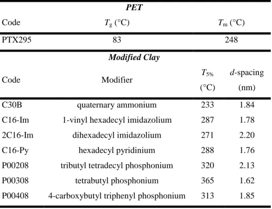
In the first phase of the project, three different types of organomodified clay were used: commercial ammonium-modified silicate clay, specially prepared thermally stable phosphonium and imidazolium-modified montmorillonite (MMT). The ammonium-modified clay under the trade name Cloisite30B was purchased from Southern Clay Co. The other clays were prepared by modification of MMT with phosphonium [99], imidazolium pyridinium surfactants [100] in laboratory. Chemical structures, 5 wt% mass reduction related temperature, T5%, and basal
spacing, d001, of the surfactants are summarized in Table 3.1.
Table 3.1: The characteristics of the organically-modified clays
Code Modifier T5%
(°C)
d-spacing
(Å)
C30B quaternary ammonium 233 18.4
P00208 tributyl tetradecyl phosphonium 320 21.3
P00308 tetrabutyl phosphonium 365 16.2
P00408 4-carboxybutyl triphenyl phosphonium 313 18.5 C16-Im 1-vinyl hexadecyl imidazolium 287 17.8
2C16-Im dihexadecyl imidazolium 271 22.0
C16-Py hexadecyl pyridinium 288 17.6
As seen, phosphonium, imidazolium and pyridinium-modified clays exhibit higher thermal stability, as indicated T5% in TGA experiments, than Cloisite30B (C30B).
After characterizing the prepared PCNs in the first step, C30B and P00208 were selected for the second part of the experiments to produce PCN films.
3.2 Process
In the first step, preliminary tests were done in a batch internal mixer Brabender at 50rpm, temperature range 260-290 °C and residence time 5-10 min. After finding the processing parameters, melt compounding was carried out in a co-rotating twin screw extruder (TSE) (Leistritz ZSE 18 HP) available in the chemical engineering department of Ecole Polytechnique (Figure 3.2). The TSE screw diameter was 18 mm and the length/diameter (L/D) ratio was 40. A circular die of 2 mm diameter was mounted on the barrel exit, and a water-ice bath was employed to cool the extrudate.
Figure 3.2: Screw configuration: a) 1st mixing zone with 30, 60 and 90° elliptical elements; b) 2nd mixing zone with 30° elliptical elements; c) 3rd mixing zone with 60° elliptical elements
In order to obtain a uniform feeding mixture, PET pellets were ground into a powder and dry-mixed with clay before feeding into the TSE hopper. PCNs were prepared at 175 rpm and temperature profile of 240, 275, 270, 265, 265, 265, 265 and 260 °C. Organoclay content was 2 wt% (nominal value) for the cases of C30B and phosphonium-modified MMT. In the imidazolium and pyridinium-modified MMT cases, the organoclay content was 1.25 wt% (nominal value). The nanocomposites extrudates were granulated and compression molded at