HAL Id: hal-01687309
https://hal.archives-ouvertes.fr/hal-01687309
Submitted on 15 Mar 2019HAL is a multi-disciplinary open access archive for the deposit and dissemination of sci-entific research documents, whether they are pub-lished or not. The documents may come from teaching and research institutions in France or abroad, or from public or private research centers.
L’archive ouverte pluridisciplinaire HAL, est destinée au dépôt et à la diffusion de documents scientifiques de niveau recherche, publiés ou non, émanant des établissements d’enseignement et de recherche français ou étrangers, des laboratoires publics ou privés.
Identification of mechanical properties of CuSil-steel
brazed structures joints: a numerical approach
A. Nafi, Mohammed Cheikh, O. Mercier
To cite this version:
A. Nafi, Mohammed Cheikh, O. Mercier. Identification of mechanical properties of CuSil-steel brazed structures joints: a numerical approach. Journal of Adhesion Science and Technology, Taylor & Francis, 2013, 27 (24), pp.2705-2713. �10.1080/01694243.2013.805640�. �hal-01687309�
Identification of mechanical properties of CuSil-steel brazed
structures joints: a numerical approach
A. Nafia, M. Cheikhb* and O. Mercierc†
aEcole Nationale Supérieure d’Arts et Métiers, Marjane II, Beni M’hamed, B.P. 4024 Meknès,
Morocco;bUniversité de Toulouse, IUT de Figeac, ICA (Institut Clément Ader), Avenue Nayrac, F-46100 Figeac France;cUniversité de Toulouse, Mines Albi, ICA (Institut Clément Ader),
Campus Jarlard, 81013 Albi Cedex 09, France
In this paper, the inverse method is used to identify the mechanical characteristics of a brazed joint. This technique is based upon tensile tests and/or shearing test com-bined with the results of a calculation using finite elements method. This paper shows that calculation of a brazed assembly under an elastic behavior assumption is flawed. A correct study of a brazed assembly must be done under an elastoplastic assumption. The presented method will be used for calculation of molds manufac-tured by stratoconception (sheet metal assembling).
Keywords: brazed assemblies; inverse method; numerical identification; optimization
1. Introduction
Stratoconception is a patented technique for rapid prototyping or rapid tooling. For injection molds applications the bulk work-piece is broken down into elementary layers using a specific CAD software. Layers are cut using a milling center. The last step for injection molds application is the bonding of layers, e.g. by brazing. A polishing stage concludes the process. Stratoconception belongs to the family of laminated object man-ufacturing technology.[1–3] Today, softwares are readily available in order to machine and to assemble the layers comprising the mold.1 A critical stage in the assembly of the
mold block steel layers is brazing. This operation consists of assembling two base met-als, identical or different, using a filler whose melting point is infinitely lower than that of the substrates. While Kucza et al. [4,5] represent a valuable reference on the subject, albeit mostly focused on brazing of aluminum sheets, numerous practical problems are yet to be fully solved, most notably: preparation of joining surfaces, influence of braze thickness and temperature profile, proper coasting of layers, etc. [6].
For numerical simulation, the calculation of brazed assembly poses the problem of identifying adhesive characteristics after brazing. In fact, mechanical characteristics of the filler material in an original state cannot be used for calculation of a brazed assembly. The brazing cycle modifies mechanical characteristics of this filler. Fusion
*Corresponding author. Email: mcheikh@univ-tlse2.fr
phenomenon between the substrates and the joint also alters its characteristics.[7] Since the joint is fairly thin (<100μm), the physical characteristics of the joint will be gener-ally modified by the brazing process.
In this work, a numerical method to identify mechanical characteristics of the joint by inverse method using results of tensile test and/or shearing test is used. One can see that calculation of a brazed assembly with an elastic behavior is flawed.[8] Correct study of brazed assembly must be carried out under elastoplastic assumption.
The first section presents the simulation of a shear test with an elastic material behavior. The second section presents an elastoplastic model used to calculate the brazed assembly. Coefficients of the joint’s model material and substrates are identified after the presentation of the inverse method used in this study. The following section shows that brazing modifies the joint’s characteristics. Inverse method is used to iden-tify the coefficients of joint’s model material after brazing in a shear test.
2. Simulation of a shear test of a brazed assembly
In order to show the need for an elastoplastic model for calculation of a brazed assem-bly, we carry out a calculation by finite element to simulate shear test of a brazed speci-men. In this simulation, joint and substrates materials behavior is assumed to be elastic. Evolution of von Mises stress on the level of the interfaces between joint and substrates is used as an evaluation criterion of this calculation. The specimen is made up of two steel substrates brazed by a joint. Steel substrate is commercially available as X40CrMoV8 tool steel. It is brazed under vacuum using silver-copper alloys, including commercial grades CuSil (73% Ag and 27% Cu). Length of overlap is L ¼ 5 mm and thickness of the joint is e2= 70μm (Figure 1). Considering the geometrical and loading
symmetry of the specimen, only half of the specimen is used as shown in Figures 2 and 3. The model is descritized with 974 2D linear elements and 818 nodes; hence, 1636 degrees of freedom (DOF) for the problem. Piloting of the shear test is carried out by imposing displacement on the right side of the specimen. The remainder of the boundary conditions is composed of an embedding of the left side and a condition of symmetry on the median axis of the specimen. This condition of symmetry is modeled by an elimination of the movement along the y axis (vertical axis on the view). Joint and substrate materials are modeled with Young’s modulus of 220 and 80 Gpa for steel and joint, respectively. Poisson’s ratio is 0.3 for the two materials. Mesh and calculation of this example are carried out with Z!eBuloN.2
Figure 4 presents the von Mises stresses at the levels of the lower interface and higher interface between the joint and the substrates. This figure shows well that the values of the stresses are over-estimated, in particular, at the extremities of the joint. In joint medium, the value of the stresses approaches 1000 Mpa and reaches 5000 Mpa at
0 0.5 1 1.5 2 2.5 3 3.5 4 4.5 5 0 1 2 3 4 5 6 (Gpa) Overlap distance (mm) Lower interface Higher interface
Figure 4. Evolution of von Mises stresses on the levels of lower and higher interfaces between joint and substrates: elastic calculation case.
Figure 3. Mesh of half specimen with zoom on the right corner. Figure 2. Applied boundary conditions.
the extremity of the joint. These values are not realistic; stresses never reach these val-ues without breaking of the specimen. This example demonstrates that simulation of brazed assembly with an elastic behavior is erroneous. It is necessary to take into account the elastoplastic behavior of materials of joint and substrates, as shown in the following section.
3. Elastoplastic behavior of a brazed joint 3.1. Elastoplastic constitutive equations
Viscoplastic model with internal variables of Lemaitre and Chaboche [9] is used as a law of mechanical behavior. Strain is partitioned into an elastic part and a plastic part:
e ¼ eeþ ep ð1Þ
Elastic domain is defined by means of von Mises equivalent stress, introducing both kinematic X and isotopic R hardening, such as:
f ðr; X ; RÞ ¼ ð3=2ðr % X Þdev: ðr % X ÞdevÞ12% R % r
y ð2Þ
with ry as the initial yield stress. Viscoplastic flow is governed by normality rule, so
that:
_
ep ¼ _porof ð3Þ
with p as the cumulated plastic strain. Hardening depends on state variables, a and p: X ¼23Ca with _a ¼ _ep%32CDX _p ð4Þ and
R ¼ Qð1 % expð%bpÞÞ ð5Þ
Parameters Q and b define variation of isotropic hardening R. Parameters C and D characterize kinematic hardening X . This kinematic variable X represents evolution of elastic limit under the Bauschinger effect. Coefficients of this hardening are identified in cyclic tests. For simplicity reasons, Baushinger effect is neglected in this study. Only isotropic hardening R is taken into account.
Plastic injection molds, which are the object of this study, are used at temperatures below than 250 °C. Lower temperatures have a minimal effect on the joint material mechanical characteristics; therefore, temperature is neglected in the model used.
3.2. Inverse method
In order to define coefficients of elastoplastic model, we use Z-optim module of the Z!eBuloN code. The Z-optim module is a generalized optimization module which may be used to identify material coefficients, geometry optimization, etc. Solving an identification problem is to minimize a functional which, for a given set of parameters,
measures the difference between model predictions and experimental observations. Functional f can be written as:
F ¼12 ðf ðxÞ % yÞTMðf ðxÞ % yÞ ð6Þ where f ðxÞ and y are the vectors of order (N & 1) simulation and experimental data, respectively. M is a diagonal matrix of order (N & N) weights, with N as the number of experimental data. During an optimization loop, an external program simulates experi-mental tests using the set of parameters provided by Z-optim. The results of this sim-ulation are compared by Z-optim to experimental curves in order to produce a better set of parameters and so on, until convergence is attained (Figure 5). The external soft-ware can be any program (Z-sim, Z!eBuloN, ABAQUS, etc.) provided that it reads the needed coefficients in ASCII format. Z-optim module is used in our case to define elasticity limit R0 and the two coefficients, b and Q, of isotropic hardening R for the two materials of the brazed assembly.
3.3. Identification of joint and substrate material behavior
In order to identify joint and substrates model coefficients, we carried out two tensile tests of two specimens with CuSil material and X40CrMoV8 steel. Stress field is homo-geneous in a tensile test. Study of a single point of a material’s useful zone is applica-ble to all points of that zone (it is not the case for deflection tests for example). In our case, it is not necessary to use a finite element code as an external program in the optimization loop. Simulation of material behavior in a point by the Z-sim module of Z!eBuloN is satisfactory.
Curves of simulation after identifications, as well as experimental results, are pre-sented in Figures 6 and 7. These results show good matching between simulation results of the identified model and the experimental tests. Coefficients of the two mate-rials are presented in Table 1.
0 200 400 600 800 1000 1200 -2 0 2 4 6 8 10 (Mpa) Strain(%) Steel Simulation Experiment
Figure 6. Experimental and simulation results in a tensile test for substrate material.
0 50 100 150 200 250 0 0.1 0.2 0.3 0.4 0.5 0.6 0.7 0.8 0.9 1 (Mpa) Strain(%) Cusil Simulation Experiment
Figure 7. Experimental and simulation results in a tensile test for the joint material.
Table 1. Behavior model coefficients of CuSil and steel identified in tensile test.
Coefficient E (Mpa) ν R0(Mpa) b Q (Mpa)
Steel 200 000 0.3 939 11.8 147.8
4. Identification of joint material behavior after brazing
Once coefficients of the behavior models of steel and the CuSil are identified, simula-tion of the tensile tests of the first secsimula-tion with an elastoplastic behavior was run. Results of shearing test are represented in Figure 8. This figure clearly shows a diver-gence between experimental and simulation results. This diverdiver-gence is due to modifica-tion of joint material. Brazing process effectively modifies joint material behavior. This modification is primarily due to diffusion phenomenon between joint and substrates. Weak thickness of the joint facilitates the modification of the mechanical characteristics of joint material by diffusion phenomenon.[10,11] From these results, the following conclusion can be drawn: joint mechanical characteristics identified in experiments before brazing do not allow to identify joint material behavior after brazing. It is shown afterward that the inverse method described in the previous section makes it possible to identify mechanical characteristics of joint after brazing. In order to accelerate optimiza-tion procedure, we use a coarse mesh presented in Figure 9. This model is descritized with 470 2D linear elements and 379 nodes; hence, 758 DOFs for the new problem. The same boundary conditions and geometry of the first simulation (Figures 1 and 2)
0 5 10 15 20 25 0 0.02 0.04 0.06 0.08 0.1 0.12 Load (KN) Displacement (mm) Simulation Experiment
Figure 8. Load-displacement curve of shear test by simulation and experiment in the case of a joint’s material identified before brazing.
are used. In this study, we suppose that brazing does not modify steel characteristics. Only joint material characteristics are identified. In the optimization loop, the starting
0 2 4 6 8 10 12 14 16 0 0.02 0.04 0.06 0.08 0.1 0.12 Load (KN) Displacement (mm) Simulation Experiment
Figure 10. Load-displacement curve of shear test obtained by simulation and experiment with joint’s material identified after brazing by inverse method.
Table 2. Behavior model coefficients of the joint’s material identified after brazing.
Coefficient E (Mpa) ν R0(Mpa) b Q (Mpa)
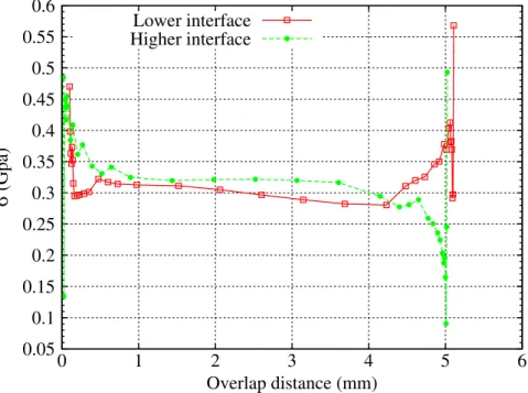
CuSil 72 000 0.3 150 10 156 0.05 0.1 0.15 0.2 0.25 0.3 0.35 0.4 0.45 0.5 0.55 0.6 0 1 2 3 4 5 6 (Gpa) Overlap distance (mm) Lower interface Higher interface
Figure 11. Evolution of von Mises stresses on the levels of lower and higher interfaces between joint and substrates: elastoplastic calculation case.
values used are the values obtained before brazing and identified in the previous section (Table 1). Figure 10 shows new load-displacement curve after new identification of the brazed material. This curve shows good matching between the model identified by the used numerical method and experimental results. New obtained characteristics are presented in Table 2. Figure 11 presents new distribution of von Mises stresses at the level of the interface between joint and substrates. The values of these stresses range between 200 and 300 Mpa in the central zone of the joint. In the joint sides, these stres-ses do not exceed 600 Mpa.
5. Conclusion
This study showed that brazing modifies the mechanical characteristics of a joint. Mechanical characteristics identified in experiments before brazing cannot be used for calculation of a brazed assembly. This study uses an inverse method, making it possible to identify elastoplastic behavior of a joint after brazing. Results obtained show a very good matching between experimental tests and simulation results.
Notes
1. One can see http://www.stratoconception.com for more details.
2. See http://www.nutnumerics.com for more information about this code.
References
[1] Barlier C. Procédé pour la création et la réalisation de pièces par CAO [Method for the creation and reallisation of parts with C.A.D and parts obtained that way]. Eurpean patent N° EP 0 585 502. 1991.
[2] Nafi A. Etude expérimentale et numérique du comportement mécanique de moules d’injec-tion de plastique obtenus par le procédé de stratoconcepd’injec-tion [Thèse universitaire] [Experi-mental and numerical study of the mechanical behaviour of thermoplastic injection moulds obtained by Stratoconception, University Thesis]. Albi: Université de Toulouse III; 2005. [3] Bryden BG, Pashby IR. Sequential laminated tooling joined by brazing for injection
mould-ing. Rapid Prototyping J. 1999;5:89–93.
[4] Kucza JC, Uhry A, Goussain JC. Le brasage fort de l’aluminium et ses alliages [Strong brazing of aluminum and its alloys]. Soudage et techniques connexes [Welding and Associ-ated Techniques]. 1991;45:18–29.
[5] Kucza JC, Uhry A, Goussain JC. L’optimisation du procédé de brasage par la méthodologie des plans d’expériences [Optimization of brazing process per the methodology experimental design]. Soudage et techniques connexes [Welding and Associated Techniques]. 1992;46:35–40.
[6] Leroux S, Le Ny J, Guéneauand C, Camel D. Condensation of silver-copper alloys in a solid–liquid domain of the phase diagram. Surf. Coat. Technol. 2000;125:361–365.
[7] Rageb F. Etude du comportement mécanique des assemblages brasés [Thèse d’université] [Optimization of brazing process per the methodology experimental design, University Thesis]. Paris: École nationale supérieure d’arts et métiers; 1990.
[8] Cheikh M, Loredo A, Coorevits P. Modelisation of the stress vector continuity at the inter-face of bonded joints. Int. J. Adhes. Adhes. 2001;21:249–257.
[9] Lemaitre J, Chaboche J-L. Mécanique des matériaux solides. 2nd ed. Paris: Dunod; 1988. [10] Lovato G, Moret F, Le Gallo P, Cailletaud G, Pilvin P. Detarmination of brazed joint
constit-uve law by inverse method. Journal de physique. 1994;IV:1135–1140.
[11] Lovato G. Rhéologie des joints brasés: étude expérimentale et détermination par méthode inverse [Thèse d’université] [Study the mechanical behavior of brazed joints, University Thesis]. Paris: École des Mines de Paris; 1995.