HAL Id: hal-02081359
https://hal-mines-albi.archives-ouvertes.fr/hal-02081359
Submitted on 1 Apr 2019
HAL is a multi-disciplinary open access
archive for the deposit and dissemination of
sci-entific research documents, whether they are
pub-lished or not. The documents may come from
teaching and research institutions in France or
abroad, or from public or private research centers.
L’archive ouverte pluridisciplinaire HAL, est
destinée au dépôt et à la diffusion de documents
scientifiques de niveau recherche, publiés ou non,
émanant des établissements d’enseignement et de
recherche français ou étrangers, des laboratoires
publics ou privés.
Review on the research of hydrogen storage system fast
refueling in fuel cell vehicle
Mengxiao Li, Yunfeng Bai, Caizhi Zhang, Yuxi Song, Shangfeng Jiang, Didier
Grouset, Mingjun Zhang
To cite this version:
Mengxiao Li, Yunfeng Bai, Caizhi Zhang, Yuxi Song, Shangfeng Jiang, et al.. Review on the research of
hydrogen storage system fast refueling in fuel cell vehicle: Review. International Journal of Hydrogen
Energy, Elsevier, 2019, 44 (21), pp.10677-10693. �10.1016/j.ijhydene.2019.02.208�. �hal-02081359�
Review on the research of hydrogen storage system
fast refueling in fuel cell vehicle
Mengxiao Li
a,1, Yunfeng Bai
a,1, Caizhi Zhang
a,*, Yuxi Song
a,
Shangfeng Jiang
b, Didier Grouset
c,**, Mingjun Zhang
daSchool of Automotive Engineering, The State Key Laboratory of Mechanical Transmissions, Chongqing Automotive
Collaborative Innovation Centre, Chongqing University, Chongqing, 400044, China
bZhengzhou Yutong Bus Co. Ltd., Yutong Industrial Park, Yutong Road, Zhengzhou, Henan Province, 450061, China
cRAPSODEE, UMR CNRS 5302, IMT Mines-Albi, Campus Jarlard, 81013 Albi, CT Cedex 09, France
dBeijing PERIC Hydrogen Technologies Co. Ltd, Qingnian Road, Damei Center, Chaoyang District, Beijing, 100123,
China Keywords: Hydrogen storage Fast filling Temperature rise CFD Strategy
a b s t r a c t
A comprehensive review of the hydrogen storage systems and investigations performed in search for development of fast refueling technology for fuel cell vehicles are presented. Nowadays, hydrogen is considered as a good and promising energy carrier and can be stored in gaseous, liquid or solid state. Among the three ways, high pressure (such as 35 MPa or 70 MPa) appears to be the most suitable method for transportation due to its technical simplicity, high reliability, high energy efficiency and affordability. However, the refueling of high pressure hydrogen can cause a rapid increase of inner temperature of the storage cylinder, which may result not only in a decrease of the state of charge (SOC) but also in damages to the tank walls and finally to safety problems. In this paper, the theo-retical analysis, experiments and simulations on the factors related to the fast refueling, such as initial pressure, initial temperature, filling rate and ambient temperature, are reviewed and analyzed. Understanding the potential relationships between these param-eters and the temperature rise may shed a light in developing novel controlling strategies and innovative routes for hydrogen tank fast filling.
Contents
Introduction . . . 00
Hydrogen storage systems . . . 00
Comparison of hydrogen storage ways . . . 00
Comparison of hydrogen storage vessel . . . 00
Effects of thermo-mechanical effects on hydrogen storage tanks . . . 00
Theoretical analysis . . . 00
* Corresponding author. ** Corresponding author.
The effects of parameters on temperature rise during refueling . . . 00
Effect of initial pressure . . . 00
Effect of filling rate . . . 00
Effect of inlet temperature (or feeding temperature) . . . 00
Effect of cylinder dimension or cylinder type . . . 00
Effect of initial and ambient temperature . . . 00
CFD simulations . . . 00
Geometry grid . . . 00
Turbulence models . . . 00
Real gas model . . . 00
Definite conditions . . . 00
The safety and fast filling strategies . . . 00
Filling rate control strategy . . . 00
Refueling with multi-stage initial pressures . . . 00
Determining pre-cooling temperature from refueling parameters . . . 00
Conclusion . . . 00
Acknowledgments . . . 00
References . . . 00
Introduction
The proton exchange membrane (PEM) fuel cells enjoy the merits of low operating temperature, low noise, quick startup
and high efficiency[1,2]. PEMFCs can generate powers from a
few Watt to hundreds of kilo-Watt and are already in the commercialization stage in three areas: transportation,
sta-tionary power system and portable market[3,4]. The most in
sight and promising application field of PEM fuel cells is in the
transportation [5], including automobiles, buses, scooters,
boats and unmanned aerial vehicles (UAV) [6]. During the
recent years, almost all major car manufacturers have declared intending or being manufacturing FC vehicles. Hydrogen en-ergy is a high promising candidate as an enen-ergy carrier for fuel cell vehicle since it can be produced locally from a variety of renewable sources with nontoxic, noncorrosive, environment
friendly, high efficiency processes[7]. Nevertheless, there is no
easy or immediate solution for on-board hydrogen storage currently. Hydrogen storage is an important issue that restricts the widely application of fuel cell vehicles.
At present, the possible storage methods of hydrogen are
compressed gas, cryogenic liquid and metal hydride[8]. In
transportation field, the compressed gas storage method is more common than other methods due to its technical simplicity, high reliability, acceptable efficiency and
afford-ability[7,9,10]. Nevertheless, considering the process of fast
refueling, the temperature rise is a significant issue which is
caused by three main thermodynamic phenomena [11].
Firstly, the kinetic energy of the fast-flowing hydrogen con-verted into the internal energy gas generates lots of heat in the process of filling. Secondly, the hydrogen expanding through a throttling valve results in an increase of temperature, called as Joule-Thomson effect. Thirdly, the compression of hydrogen in the tank during its filling causes a temperature rise, too. Moreover, the temperature rise not only reduce the SOC of the hydrogen tank but could also bring safety hazards. Thus,
hydrogen fast charging is a serious process that needs to be considered with care to reduce risks.
In practice, several parameters (e.g. the initial pressure, initial temperature of hydrogen, the filling rate and so on) have various influences on the final temperature. To investigate the relationships between the temperature and the parameters, several experiments and simulations investigated the tem-perature rise within a compressed cylinder. In order to study the thermal behavior during hydrogen fast filling process,
Johnson et al.[10]developed one-dimensional and 3D models
and conducted experiments for comparing. The mass flow rate has a more significant effect than other parameters. However, drivers do not expected to spend a longer time for refueling the hydrogen vehicles compared to the conventional liquid fuel
powered vehicles [12]. Nevertheless, the temperature rise
during the fast filling process is a serious issue and it is sig-nificant to develop an effective strategy to achieve the safe and fast refueling. In view of the influence of initial gas tempera-ture on temperatempera-ture rise, precooling measures are adopted to improve the fast filling of hydrogen and have been validated to be the most effective way to reduce the final temperature. In addition, the process of multi-stage filling is adopted to
decrease the energy consumption and Guo et al.[13]designed a
dynamic simulation module to optimize the gas cycling test system in a view of energy consumption reduction.
The construction and operation of refueling stations hydrogen refueling stations requires high capital investment
[14e16]. Adopting appropriate operational strategies could reduce capital investment while improving equipment utili-zation. Hence, the research of fast filling strategies is neces-sary. At present, the process of multi-stage filling combined with the measure of precooling have been widely applied in most filling stations. The precooling of hydrogen could decrease the temperature rise effectively and the process of multi-stage filling could reduce the energy consumption. The configurations of off-site hydrogen generation filling station
are shown as Fig. 1 [8]. The hydrogen source is the high-pressure tube-trailers. The tube trailers can be used to sup-ply hydrogen to the buffer storage vessels through the compressor. The high-pressure tubes (25 MPa or higher) on the tube trailer can also be used to initially charge the vehicle's tank before the pressure drops. Then the suitable control strategy is adopted to refuel the vehicle tank successively from the multi-stage hydrogen storage system. The pre-cooling system can be determined whether to enable or not according to the ambient temperature.
In this paper, the current methods on controlling the temperature rise during refueling, such as changing the gas initial temperature, initial pressure, ambient temperature and pre-cooling process are reviewed. The organization of this
paper is as follows. SectionHydrogen storage systems
pre-sents hydrogen storage systems, such as compressed hydrogen storage, liquid hydrogen storage and metal hydride hydrogen storage. Based on compressed hydrogen storage, four different types of tanks are compared. The thermody-namic mechanism and theoretical analysis of temperature
rise are reviewed in SectionTheoretical analysis. SectionThe
effects of parameters on temperature rise during refueling
summarizes the current experiments and simulations on
fast and safe hydrogen refueling technology. Section CFD
simulationssummarizes a series of CFD models on the flow field and temperature field during the process of hydrogen
charging. SectionThe safety and fast filling strategiesstudies
the safety and fast filling strategies. Finally, conclusion is
given in SectionConclusion.
Hydrogen storage systems
Comparison of hydrogen storage ways
In the development of hydrogen energy, storage is considered as a key issue for the widespread use in transportation,
sta-tionary power system and portable market[17,18]. At present,
the most common ways to store hydrogen are compressed
hydrogen storage, cryogenic liquid and metal hydride[19,20].
Recently, Abdalla et al.[21]summarized the storage methods
of hydrogen in one of their studies, covering compressed hydrogen, liquefied hydrogen, metal hydride, carbon nano-tubes, liquid organic hydrogen carrier and metal-organic framework. There is amount of ways for storing hydrogen
fuel in different forms as show inTable 1 [22e26]. Compared
with the above several methods, compressed gas storage is more popular due to its technical simplicity, high reliability,
acceptable efficiency and affordability[27].
Comparison of hydrogen storage vessel
The key technology for the widespread use of compressed hydrogen is the storage vessel. The requirements of the ma-terial used in the hydrogen storage vessel are: safe, reliable, cost effective and any strong interaction with hydrogen or any reaction. As early as 1880, pressure vessel use has been re-ported: hydrogen was stored in wrought iron vessel at 12 MPa
for military application[19]. Currently, hydrogen vessels are
mainly divided into 4 different types (Type I to Type IV) as
shown in Table 2 [21,28e30]. It is the most mature and
commonly adopted solution of hydrogen storage in vehicles
[7,31]. Usually hydrogen cylinders can be pressurized up to
Fig. 1 e Schematic representation of the refueling station components[8].
25 MPa, 35 MPa or 70 MPa. Considering the driving range and limited space in vehicle, 70 MPa is to be the most economic
pressure for onboard storage[28,32].
Comparing the above four types, it is found that Type I and Type II cannot be used in vehicles due to low hydrogen storage density and serious hydrogen embrittlement problems. In the industry of fuel cell vehicles (FCVs), Type III and Type IV are
widely used for weight minimization[7,31,33]. However, Type
III and IV have different behavior with respect to temperature rise due to the material differences. Some characteristic
property data of Type III and IV are shown inTable 3,
ac-cording to Ref.[29].
In China, the technology development of Type III is rela-tively mature. Among them, the 35 MPa vessel has been widely used in fuel cell vehicles in recent years and the 70 MPa vessel is near the market. However, the shortage of carbon fiber and resin, and the performance of these materials block the development of hydrogen vessel. The Type IV vessel have
only recently been developed[28].
At present, most of the developed fuel cell vehicles use
high-pressure cylinders to store hydrogen on board.Table 4
documents the key parameters of several fuel cell vehicles. The Honda FCX is equipped with two 35 MPa tank that can
achieve a 156.6 L hydrogen capacity [34]. Toyota FCHV-adv
used four type IV 70 MPa tanks to supply hydrogen for its fuel cell stack, the total volume of the four tanks is 156 L, which could achieve a driving range in practical driving conditions of
at least 500 km with a roughly 10 min fueling time[35,36]. In
order to reduce the weight, size and cost of the high-pressure
hydrogen storage system, Toyota“Mirai” employs two new
larger diameter tanks (60 L and 62.4 L). They can store nearly 5 kg hydrogen in 3 min and provide a driving range of
approximately 500 km[36]. Recently, Hyundai released a new
fuel cell SUV, NEXO, which features three same fuel tanks with a total capacity of 156 L and 6.3 kg and with a fueling time of 5 min. It is said that the newly fuel cell vehicle can achieve a driving range of up to 800 km under current NEDC testing cycle.
Effects of thermo-mechanical effects on hydrogen storage tanks
In the application process, compressed-hydrogen tanks for vehicles are fatigued by cycles of filling and consumption
[46,47]. Pressure vessels are directly subjected to the cyclic loading of both high pressure and extreme temperature. The temperature in the tank increases significantly during the fast filling process but declines in the process of gas usage routine. The violent changes of temperature can lead to severe ther-mal stress due to the mismatch in the coefficient of therther-mal expansion of adjacent plies with different fiber orientations, which accompanied by internal pressure during numerous charge-discharge processes. The superposition of thermal stress and internal pressure will cause obvious lamination damage in the form of micro-cracks in the resin, and then lead to the failure of the composite material. Furthermore, the temperature changes will seriously affect mechanical prop-erties of the epoxy resin and carbon fibers. The fracture toughness of the epoxy resin matrix will decrease seriously at low temperatures, while the inter laminar shear strength of the composites will dramatically decrease at high tempera-ture. Thus, the strength and fatigue life of the composite
vessel are seriously affected[48].
Indeed, risks of an early failure appear when the type III vessels are subjected to cyclic pressures and permeation
problems happen for the type IV[49]. Tomioka et al.
investi-gate the influence of the environmental temperature on the fatigue strength of compressed-hydrogen tanks (Type III and Type IV). The fatigue strength of the Type III tank decreases in a low temperature environment and increases in a high-temperature environment. However, the fatigue strength of
type IV decreased in a high-temperature environment [50].
The temperature rise result in stratification between the plastic liner and the composite wrapping materials of type IV
tank [28]. Some experimental researches on the fatigue of
composite hydrogen storage vessels are shown inTable 5.
Theoretical analysis
Temperature of the cylinder could maintain within the spec-ified threshold after refueling is expected. Therefore, investi-gating the mechanism of temperature rise during the fast filling process becomes the focus of research. There is a rapid increase in hydrogen temperature due to three main
ther-modynamic phenomena during hydrogen filling process[51].
Firstly, the kinetic energy of the fast-flowing hydrogen
Table 1 e Hydrogen storage types and comparisons.
Category Type Advantages Issues
Gas storage Compressed hydrogen High efficiency, convenient, mature technology.
Expensive cylinder and the immature technology of fast filling. Liquid storage Liquid hydrogen High liquid density and storage
efficiency.
Large consume of energy and time, low temperature.
Carbon nanotubes Gaseous hydrogen Highly porous structure and particular interaction between carbon atoms and gas molecules.
Immature technology and hydrogen capacity depends on many factors. Chemical storage (metal hydride) MgH2 CaH2 NaH
High safety, high purity of hydrogen, good reversible cycle performance, large volume of hydrogen density.
Absorbing impurities, reducing the hydrogen capacity and the lifetime of tank.
Physical storage (metal organic framework)
Porous coordination network
Highly porous, high uptake of H2 and specific surface areas.
Hydrogen storage temperature is far below operating temperature.
converted into the internal energy gas generates lots of heat in the process of filling. Secondly, the compression of hydrogen in the tank during its filling causes a temperature rise, which is the most important among all factors leading to tempera-ture rise. Thirdly, the hydrogen expanding through a throt-tling valve results in an increase of temperature, called as Thomson effect. Other than general gases, the Joule-Thompson negative effect appears during hydrogen expend through a throttling valve due to its unique nature. In the meantime, a good news is that part of the heat in the cylinder may transfer to the ambient due to the difference in temper-ature. Nevertheless, most part of the heat is stored in the wall of the cylinder, which lead to the temperature rise of the cylinder. Taking into account the simplicity of the model, the
hydrogen filling process could be simplified asFig. 3.
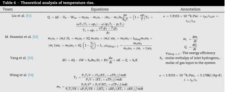
The theoretical analysis is mainly based on the simplified thermodynamic model. The energy and mass conservation equations combined with the real gas equation of state to obtain the relationship of the temperature and pressure in initial state and final state respectively. In the theoretical model of Liu et al.
[51]as shown inTable 6. The internal energy and kinetic energy
of hydrogen were considered. Considering that refueling time is short and assuming it an adiabatic process, the heat trans-ferring to ambient is ignored. Another assumption is that initial temperature within the cylinder equals to hydrogen tempera-ture before filling. The result shows the final hydrogen tem-perature in the cylinder could be calculated accurately with the relative parameters in the simplified process. In another work
accomplished by M. Hosseini et al.[52], additional work have
been done is that the exergy of the hydrogen in the cylinder is also investigated, which could illustrate the thermodynamic
mechanism more comprehensively. Yang et al.[53]carried out
the model analysis with the gaseous hydrogen treated as an ideal or a non-ideal gas and the refueling process analyzed based on adiabatic, isothermal, or diathermal condition of the cylinder. A constant feed-rate is assumed in the analysis. The consequence shows that the adiabatic and isothermal condi-tions were the lower and upper bounds of the filling time for a given final target pressure. Assuming that the specific heat is
constant (Cv¼ 5.178 kJ/kg K), Wang et al.[54]developed the
thermodynamical model based on the conservation equation of energy. The mass and temperature after filling could be obtained.
The theoretical analysis shows the change of temperature clearly with mathematical formula. As we can see, the tem-perature rise of hydrogen is mainly determined by filling pa-rameters. In addition, some other parameters such as the geometrical parameters of the cylinder may also affect the state of cylinder after filling. Hence, further research of the effects of these parameters is required.
The effects of parameters on temperature rise
during refueling
The gas temperature may rise significantly during the high-pressure hydrogen cylinder refueling and lead to a failure of
the hydrogen storage tank[29]. Furthermore, the high
tem-perature also reduces the hydrogen density in the tank, resulting in a reduction of the final mass delivery and in turn, decreasing the driving range of the hydrogen vehicles. Hence, the study of temperature rise during refueling is a significant
concern regarding hydrogen safety[55]. Syrian et al.[29]and
Zheng et al. [7] carried out experimental studies and CFD
simulations on type III vessels. Kim et al.[28], Galassi et al.[17]
and Melideo et al.[56]worked on type IV vessels. Heitsch et al.
[57]and Melideo et al.[12]compared the influence of the type
(III or IV) on temperature rise in cylinders during fast
refuel-ing. For safety concern, the GTR-HFCV[58], the SAE-J2579[59]
and the ISO-15869 [60] have restricted the maximum wall
temperature inside the hydrogen vessel below 358 K and the maximum fueling pressure has to limited below 125% of the designed pressure. Therefore, the temperature rise in the hydrogen vessel during the fueling process has to be controlled within these allowed limitations. Investigating the
Table 2 e Different types of hydrogen compressed tank.
Cylinder types
Materials Features Applications Hydrogen storage
pressure and mass percent (WT%)
Type I All metal Heavy, internal corrosion For industrial, not suited for vehicular use
17.5e20 MPa 1 WT%[21]
Type II Metal liner with hoop wrapping
Heavy, short life due to internal corrosion
Not suited for vehicular use 26.3e30 MPa Type III Metal liner with full
composite wrapping
Lightness, high burst pressure, no permeation, galvanic corrosion between liner and fiber
Suited for vehicular use. 25e75% mass gain over I and II
35 MPa: 3.9 WT% "70 MPa: 5 WT%
Type IV Plastic liner with full composite wrapping
Lightness, lower burst pressure. Permeation through liner, high durability against repeated charging
Simple manufacturability
Longer life than Type III (no creep fatigue).
70 MPa: more than 5 WT%,
Table 3 e The property of type III and type IV tank.
Cylinder types Thermal
conductivity (W/mK)
Density
(Kg/m3) capacity (J/kgSpecific heat
K) Type III: Metal liner 167 2730 900 Laminate 1 1494 938 Type IV: Plastic liner 0.3 947 1880 Laminate 1.5 1600 1400
fueling parameters, such as the initial pressure, initial gas temperature, ambient temperature, filling rate and even the cylinder dimensions, is very significant to control the final
tank gas and wall temperature below 85#C effectively.
Effect of initial pressure
During the fast filling process, the initial pressure in the cyl-inder has a significant effect to the final temperature. Higher initial pressure means more hydrogen initially stored in the tank and a lower pressure ratio between final and initial pressure ration, which both can mitigate the temperature rise
during refueling[61]. In order to estimate the influence of the
different initial pressures on the final temperature, several experiments and simulations completed by researchers are
shown inTable 7.
In order to study the relationship between the initial pressure and the final temperature during the refueling pro-cess, various experiments with different facilities and condi-tions have been conducted. The negative influence of the initial pressure on the final temperature can be seen. An
experimental system built by Zheng et al.[7]was equipped
with sixteen thermocouples and a pre-cooling system. Their results indicated the final temperature of the gas decreases about 4.5 K when the initial pressure increases 5 MPa. In the
meanwhile, other experiments developed by Kim et al.[28]
and Liu et al.[51]also validates the maximum temperature
decreases almost linearly as the initial gas pressure increases.
Grouset et al.[64], using a 0D model for the gas and a 1D model
for the tank wall, also reports a linear variation with a
sensi-tivity coefficient of 1.06#C/MPa at 70 MPa and "1.64#C/MPa at
70 MPa. Therefore, the initial pressure has an important effect on the temperature rise. In order to limit the filling tempera-ture under the threshold, the optimal filling initial pressure must be considered combined with other parameters.
Effect of filling rate
With the wide application of hydrogen energy in automobiles
[5], the length of the fill time becomes the focus of people's
attention. However, increasing the filling rate to minimize the fill time may result in a final temperature exceeding the
Table 4 e Specifications of several fuel cell vehicles [14,37e45].
Vehicle name Year Max. output
(bhp/kw)
Total volume of tanks (L) and tank’ type
Driving range (km)
Honda FCX 2nd Generation 2004 / 156.6 430 Honda FCX Clarity 2008 134/100 171 386 Toyota FCV-adv 2008 121/90 156 (type 4) 483 Toyota Mirai 2014 153/144 122.4 (type 4) 502 Hyundai ix35 2014 136/100 5.63 kg under 70 MPa 594
Hyundai NEXO 2018 161/95 156 595.5
Table 5 e Experimental researches on the fatigue of hydrogen storage vessels.
Author Experiment Parameter Frequency Results analysis
Chuan-xiang ZHENG
[48]
70-MPa Fatigue test system using hydrogen as medium
The highest testing pressure of the system: 70 MPa.
The greatest hydrogen mass flow rate: 3.24 kg/min.
10 min/cycle
After 500 times fatigue test, the bursting characteristics was checked
The experimental results show that hydrogen environment fatigue affects the ultimate strength of the composite vessels: nearly 15% drop off compared with design pressure. Another sample vessel was
tested in this system until failure.
The fatigue life of another test sample is 5122 times which is much shorter than that under hydraulic fatigue test (about 12,000 times).
Tomioka
[50]
Hydraulic pressure-cycle tests to investigate the fatigue life of Type III tanks when environmental temperature and filling pressure are changed.
Low temperatures ("40#C, 28 MPa) Room temperature (15#C, 35 MPa) High temperatures (85#C, 44 MPa) Normal temperature (15#Ce35#C, (with no temperature control), 44 MPa) 1 min/cycle 10,000 cycles
The fatigue life at high
temperatures (85#C, 44 MPa) was shorter than that under other conditions. As shown inFig. 2.
Tomioka
[46]
Hydraulic pressure-cycle tests with varying environmental temperatures were conducted until the tank was broken or for 45,000 cycles. Room temperature (without temperature control) High temperatures (85#C, 95% relative humidity) Low temperature (85#C) 4 cycles/min
Cycle the pressure in the tank between less than 1 MPa and more than 125% of the normal filling pressure
The fatigue strength of the Type III tank decreases at low
temperatures and increases at high temperatures;
The fatigue life of the CFRP layer of a Type IV tank decreases in a high-temperature
threshold [65]. In order to ensure safety, it is necessary to study the relationship between the filling rate and the final temperature. Several typical experiments are presented in
Table 8.
Short filling time reduces the time for the heat transfer between the gas and the cylinder wall to evacuate the heat accumulated in the gas. Systematic studies has been under-taken on the effect of filling time and experiments with a
mount of thermocouples (type T) as shown inFig. 4have been
conducted by Dicken et al.[62]. Based on the Spallart-Allmaras
turbulence model and the real gas equation of the state, a numerical model was developed to investigate the mecha-nism of temperature rise and heat transfer within a type III
cylinder during refueling[66]. It is found that the mass flow
rate, initial pressure and inlet temperature are the main fac-tors that affect the final temperature rise. Especially the mass flow rate has a high effect, with a high, nearly exponential, growth as the mass filling rate increases. In another research
[64], the 0D gas 1D wall model shows the heat transfer is
limited by the conduction in the tank wall and the tempera-ture rise varies linearly with the filling time square root with a
sensitivity coefficient of "8.8 #C/(min)½ at 70 MPa and
"10.6 #C/(min)½ at 70 MPa. In addition, Zheng et al. [63]
revealed that the greatest increase in temperature occurs at the start of filling due to the Joule-Thomson effect. Optimized filling strategy could be developed by using a slow filling rate
at the beginning and then higher rate later without sacrificing average fueling rate. However, this has still to be demonstrated.
Effect of inlet temperature (or feeding temperature)
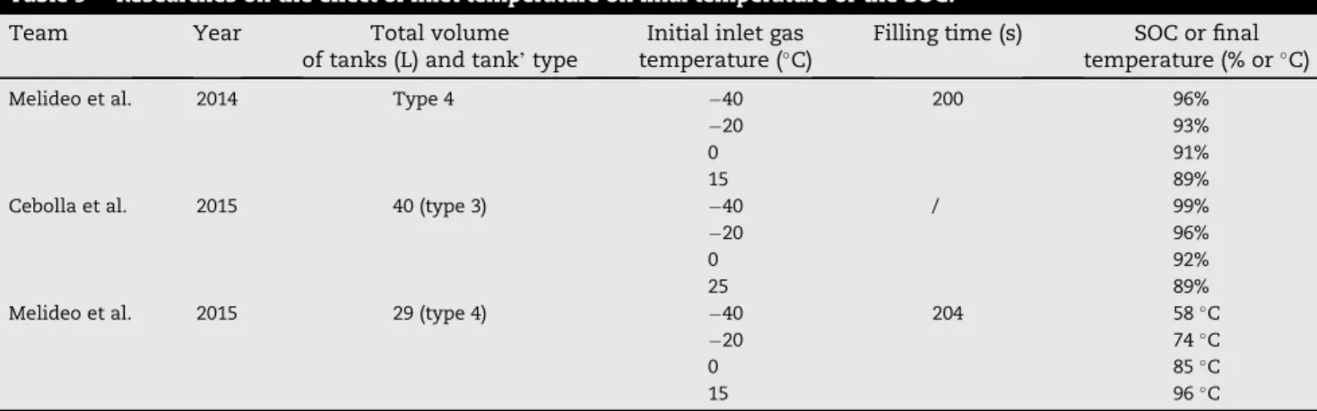
In addition, cooling the gas before injecting it into the vessel is also an effective way to meet the safety requirement. Several
researches were conducted as shown inTable 9. Melideo et al.
[56]developed different filling strategies to study its effects on
3 key-parameters: the maximum temperature, the SOC and the theoretical cooling energy demand. For energy saving, higher SOC and lower final temperature rise, precooling the gas in the second half of the filling seems more suitable.
However, Bourgeois et al.[68]showed that the most important
parameter in pre-cooling is the mass average temperature of
the gas at the inlet of the tank. In another work[12], based on a
type IV 70 MPa vessel, Melideo et al. performed a CFD model to investigate the effects of inlet gas temperature on final tem-perature during the fast filling process with pre-cooling. The results show that the final gas temperature increases when
the pre-cooling temperature increases. The 0#C is a critical
point: inlet gas temperature that higher than 0#C can lead to a
final temperature higher than 85#C.
Considering pre-cooling the gas improves the SOC value as well, a new analytical solution from a simplified lumped
parameter model was proposed by Cebolla et al. [67] to
determine hydrogen pre-cooling temperature from refueling parameters. Experiments were carried out at different gas flow rates and initial temperatures, coupling the two param-eters to get the cross effect on the final value of SOC. The case without precooling gets a higher temperature, exceeding
85#C. It can be observed that the increase in the inlet
tem-perature not only reduces the SOC, but also increases the negative impact of the flow rate on the final SOC with the
result. With its 0D gas 1D wall model, it[64]shows a linear
variation of the final temperature with the inlet temperature,
with a sensitivity coefficient of 0.99 #C/#C at 70 MPa and
0.88#C/#C at 35 MPa, but the cross effect is not characterized.
Fig. 3 e Theoretical model of filling for the composite cylinder[51].
Table 6 e Theoretical analysis of temperature rise.
Team Equations Annotation
Liu et al.[51] Q ¼ DE " U 0" Wtot¼ m2u2" m1u1" ðm2" m1Þh0Rpv gT ¼ ! 1 þapT"T2¼ lmT1ðT1þ ap1Þ " aðlp1T1" p1T1Þ T1þ ap1þ aT1p1" T1p1 p2 a¼ 1:9155 ' 10"6k=Pal ¼ cp0=cv2m¼ cv1=cv2 M. Hosseini et al.[52] m 1u1þ ðmit · Þhi ¼ m2u2þ tQ · m1ex1þ ðmit · Þexi¼ m2ex2þ Ifillingm1ex1þ ðmi · tÞexi ¼ m2ex2þ tQ · # 1 "TT0 S $ þ I1"2jfilling;1"2 ¼ m2ex2 m1ex1þ ðmi · ' tÞexi mi · ¼dmdti Q· ¼dQdt
jfilling; 1"2:The exergy efficiency
Yang et al.[53]
dU ¼ dQ " dW þ hedneðNiþ KtÞ
du dt þuK ¼ Q
·
þ heK he:molar enthalpy of inlet hydrogenne:
molar of gas input to the system
Wang et al.[54] T2 ¼P1T1V þ lT0ðRT1þ aTP1Þ R mdt P1V þ ðRT1þ aTP1ÞRmdt m2¼ P1P2V 2þ P 2VðRT1þ aTP1ÞRmdt P1T1VR þ aP1P2VR þ lðRT0þ aRP2ÞðRT1þ aRP1ÞRmdt a¼ 1:9155 ' 10"6k=Pacv¼ 5:178kJ=ðkg,KÞ l¼ cp=cv
Effect of cylinder dimension or cylinder type
At present, the type III and type IV are considered as most suitable solutions for on-board hydrogen storage. The inner layer of type III tank is made of aluminum, while the type IV inner layer is made of plastic (e.g. high density polyethylene).
Since the thermal conductivity of the plastic liner is smaller than that of the metal one, the heat transfer from the gas to the tank wall is slower in the type IV than in the type III and the type IV cylinder absorbs less heat. There are several
re-searches shown in Table 10. So the temperature evolution
have the same trend in both cylinders, but a lower final
Table 7 e Researches on the effect of initial pressure on final temperature.
Team Total volume of tanks (L) and tank's type Ambient temperature (oC) Initial to final pressure (MPa) Ref.
Zheng et al. 74 (type III) / 5.5 / 70 9.5 / 70
[7]
Liu et al. 150 (new type) 20 5 / 35 15 / 35 25 / 35
[51]
Kim et al. 72 (type IV) 20 0 / 35
5 / 35 10 / 35 15 / 35 20 / 35
[28]
Dicken et al. 40 (type III) 15 5 / 35 15 / 35 20 / 35
[62]
Zheng et al. 129 (type IV) / 5 / 70 15 / 70 25 / 70
[63]
Table 8 e Researches on the effect of filling rate on final temperature.
Team Year Total volume of
tanks (L) and tank’ type
Initial to final pressure (MPa) Filling rate (g/s) Filling time (s) Ref.
Dicken et al. 2007 74 (type 3) 10 / 35 / 40 [62]
190 370
Zhao et al. 2010 150 2 / 35 9 / [66]
19 41
Zheng et al. 2011 129 (type 4) 70 9 / [63]
19 41
Cebolla et al. 2015 40 (type 3) 2 / 78 2 / [67]
4 6 8 10
temperature is obtained in the type III tank due to the higher thermal diffusivity of the aluminum liner with respect to the plastic liner. When the inlet temperature rise, the maximum gas temperature, reached at the end of the filling, increases
linearly while the state of charge decreases linearly[69]. With
similar inlet gas temperature and other boundary conditions, the final SOC is higher in a type III than in a type IV tank. Due to the effect of heat transfer, it also found that the higher the inlet gas temperature, the higher the influence of the tank
type on the final SOC[67].
To study the effect of cylinder dimensions, cylinder A with 1652 mm length and 376 mm inner diameter was selected by
Zheng et al.[7]to be compared with cylinder B which has a
smaller length to diameter ratio. From the calculated
tem-perature profile, shown inFig. 5, the gas temperature in
cyl-inder A is non-uniformly distributed and increases gradually in axial direction, the highest temperature occurs in the caudal region while the lowest is near the inlet. Cylinder B has a good temperature homogeneity that is consistent with the experimental results. According to this result, the large length to diameter ratio may cause too high local temperature, so reducing the length to diameter ratio is beneficial to cylinder safety.
Effect of initial and ambient temperature
Concerning the ambient temperature, according [61] the
higher ambient temperature causes heat releasing difficulty. Therefore, the ambient temperature would also have an effect
on the final temperature. But following the research[64], it is
preferable to distinguish the ambient temperature (outside or external temperature) and the initial temperature of the gas
and wall tank, which, in some cases, can be different. Indeed, the initial temperature has an effect on the final temperature, whereas for the short fueling times (a few minutes) heat conduction to the outer side of the tank wall only concern a marginal part of the heat transferred to the inner part of the wall; therefore, the external temperature has a marginal effect.
A three dimensional computation model was developed to
predict the thermo-fluid dynamic behavior as shown inTable
11 [29]. The results revealed that the ambient temperature has an ignorable effect on the final temperature; but when the initial gas and wall temperature is increased, the effect become significant and the maximum temperature can exceed the safety limit. It can be concluded that the maximum temperature rise has the same trend as the initial temperature and there is a linear relationship between them. From the
numerical simulations carried out by Zhao et al.[66], an
in-crease of 1#C in the initial temperature is followed by a growth
of 0.3#C in the maximum temperature.
CFD simulations
The experiments consume many workers and material re-sources. In addition, it may be dangerous to a certain extent. Fortunately, Computational Fluid Dynamics (CFD) codes already proved to be a valuable tool for predicting the
tem-perature distribution within a tank during refueling[17]. The
CFD simulation models should be established based on tur-bulence model, real gas model and heat transfer model. Moreover, the model capabilities are evaluated by sensitivity analyses of grid refinement, turbulence model, boundary
Table 9 e Researches on the effect of inlet temperature on final temperature or the SOC.
Team Year Total volume
of tanks (L) and tank’ type
Initial inlet gas
temperature (#C)
Filling time (s) SOC or final
temperature (% or#C)
Melideo et al. 2014 Type 4 "40 200 96%
"20 93%
0 91%
15 89%
Cebolla et al. 2015 40 (type 3) "40 / 99%
"20 96%
0 92%
25 89%
Melideo et al. 2015 29 (type 4) "40 204 58#C
"20 74#C
0 85#C
15 96#C
Table 10 e Researches on the effect of cylinder dimension or type on final temperature.
Team Year Total volume of
tanks (L) and tank’ type
Initial to final pressure (MPa)
Ambient
temperature (#C)
Ref
Miguel et al. 2016 Type III 2 / 77 25 [69]
Type IV
Cebolla et al. 2015 Type III 2 / 78/77 / [67]
Type IV
Zheng et al. 2013 150 (cylinder A) 2 / 35 25 [7]
conditions, inlet pipe geometry, external wall heat transfer
coefficient and tank material properties[17]. Many scholars
have made a series of CFD simulations and validations by comparing the transient three-dimensional CFD results with experimental data for various scenarios of hydrogen filling. With using the commercially available CFD package FLUENT, CFX[70,71]the hydrogen filling process can be modeled under the given operating conditions by changing the parameters to study the effects of different temperature and pressure on the temperature rise in the cylinder. As known, the key points in CFD analysis are division of geometric grids, selection of tur-bulence model, gas state equation, setting of definite initial and boundary conditions and post-processing.
Geometry grid
Of course, the geometry should be the first consideration in the modeling process. From the perspective of computing resources, if the filling stage only is to be studied a two-dimensional model can be built firstly, because a
three-dimensional model needs to run completely for several
weeks. Melideo et al.[56]firstly validate the possibility to use
2D axisymmetric meshes successfully for the CFD simula-tions of fast filling with pre-cooling. The article shows that the temperature histories for the 3D and 2D meshes are almost completely overlapping. In other words, the 2D axisymmetric approach can be used during the filling stage. However, a 3D computational mesh has to be considered after the filling is completed. Because the speed of flow is so fast that the influence of buoyancy can be neglected during the filling stage. However, the buoyancy effect becomes more relevant in the holding time and during the emptying process due to the low flow velocity. Thus, the 3D might be more appropriate if we look at the whole process. Also considering only half of the geometry for the CFD simulations is an effective strategy to reduce the computer run-time. Melideo
et al.[72]performed simulations with the whole 3D geometry
and with half of the geometry and gave the fact that the ef-fects of that approach on the temperature histories are negligible.
Fig. 5 e Hydrogen temperature distribution within the cylinder at the end of refueling[7].
Table 11 e Researches on the effect of initial temperature.
Team Year Total volume of
tanks (L) and tank’ type
Initial to final pressure (MPa)
Initial
temperature (#C)
Ref
Suryan et al. 2012 74 (type 3) 9.3 / 35 20.4 [29]
40.4 50.4 Zhao et al. 2010 150 2 / 35 "10 [66] 0 10 20 30 40
Table 12 e Turbulence mode l. Name Mode l Realizable k-ε model vð rk Þ v t þ vð rkuj Þ v xi ¼ v vxi %# m þ mt sk $ v k v xj & þ Gk þ Gb " r ε" YM ; vð r εÞ v t þ vð r εuj Þ v xj ¼ v vxj %# m þ m t s ε $ v ε v xj & þ r1 C 1 Se " rC 2 ε 2 k þ ffiffiffiffi ffi vε p Renormalization group k-ε model vð rk Þ v t þ vð rkui Þ v xi ¼ v vxj # a k m eff v k v xj $ þ Gk þ Gb þ Sk " r ε" YM ; vð r εÞ v t þ vð r εu iÞ v xi ¼ v vxj # a k m eff v ε v xj $ þ C 1 ε ðGK k þ C 3 rGb Þþ Sr " rC 2 r ε 2 k vð r εÞ v t þ vð r εu iÞ v xi ¼ v vxj # a k m eff v ε v xj $ þ C 1 ε ðGK k þ C 3 rGb Þþ Sr " rC 2 r ε 2 k Shear stress transport k-u model vð rk Þ v t þ vð rkui Þ v xi ¼ v vxj # rk v k v xj $ þ Gk " b 0rk u vð ru Þ v t þ vð ru ui Þ v xi ¼ v vxj # rk v k v xj $ þ G u " b ru 2þ D u Reynolds stress model v ðr vt u 0iu 0jÞþ v v x k ðr uk u 0iu 0jÞ¼" v v x k ½r u 0iu 0ju 0k þ rð dkju 0iþ dkiu 0j)þ v v x k % m v v x k ðu 0iu 0jÞ & " r # u 0iu 0k v uj v xk þ u 0ju 0k v ui v xk $ " r b # gi u 0jq þ gj u 0jq $
Grid quality directly affects the rationality and correctness of CFD simulation results. Generally, the finer the mesh, the more accurate the result is, but the longer time the calcula-tions take. It is reasonable to draw as few grid cells as possible
on the premise of accuracy. And Kim et al.[28]made a simple
comparison between the results with 300, 000 cells of hybrid mesh and with 600, 000 cells of tetrahedral mesh. Finally, the results show the effect of the grid resolution on the accuracy was minimal in this study.
Turbulence models
CFD is a numerical solution to the NaviereStokes (NeS) equations to obtain all the variables of the full field. The addition of Reynolds stress equation in the NeS equations of turbulence makes the equation system unclosed. Therefore, a corresponding turbulence model has been established to be able to solve the whole flow field. The governing model suit-able for hydrogen flows needs to be determined. Four different kinds of turbulence models are summarized as shown in
Table 12. Suryan et al.[73]compared the consistency between simulation results of different turbulence models in CFD and experiments. The realizable k-ε model and the Reynolds Stress Model were identified as the most suitable turbulence models for the simulation of hydrogen gas fast filling process. The unsteady Favre averaged Navier-Stokes equations are given by Ref.[74]. vr vtþ V$ðr v!Þ ¼ 0 (1) v vtðr v!Þ þ V$ðr v!v!Þ ¼ "Vp þ V,ðtÞ þ rg (2) v
vtðrEÞ þ V$ð v!ðrE þ pÞÞ ¼ V$ðkgeffVT þ ðteff$ v!ÞÞ (3)
Real gas model
The system of NeS equations and turbulence model equations has to be closed with an equation of state for the hydrogen gas. The ideal gas model is suitable for most engineering flows. However, the compressibility effects are significant in the hydrogen tank filling and at high pressure the hydrogen gas may deviate from ideal gas behavior. Therefore, a suitable
real gas model has to be chosen. In Suryan's other articles[29],
four real gas equations are offered as shownTable 13 [75e78]
and their validity is verified.
Definite conditions
The definite conditions (initial conditions and boundary con-ditions) are the premises that the governing equations have a definite solution. Thus, based on the research on CFD model
analysis, the information shown inTable 14is summarized.
The safety and fast filling strategies
How to refuel safely and fast becomes a significant issue with the large-scale development of FCVs. The SAE J2601 protocol was developed to ensure that 5e7 kg of hydrogen could be safely filled into FCVs within 3e5 min from the station. The
safety limits of the vehicle storage system are shown inTable
15 [80]. The fueling protocol determines the fueling average pressure ramp rate (APRR) at the dispenser, which is affected by the hydrogen precooling temperature at the dispenser, the vehicle tank volume and tank initial pressure, and the ambient temperature. There are two fueling methods
involved in this protocol, known as the“lookup table” method
and the “MC formula” method. The lookup table method
provides a fixed end-of-fill pressure target. The MC method is the dynamic control of the APRR, taking advantage of the thermodynamic properties of the hydrogen tank to calculate the pressure target continuously. The current standard method of fueling for FCVs is the lookup table method.
How-ever, the“MC formula” method has a greater advantage in
reducing fueling time in certain conditions. Reddi et al. employ a physical model to compares the fueling
perfor-mance of two fueling methods[81].
In order to reduce the final temperature and minimize the energy consumption for hydrogen compression, three effec-tive control strategies of fast filling are proposed via the analysis of the relationships between temperature rise and filling parameters above. The first method is controlling the mass flow rate accurately in the filling process: slow at first and then faster. The second method is that the cylinder can be refueled with a multi-level storage system, which is composed of several hydrogen storage vessels with staged initial pres-sures. The last method is adjusting the hydrogen pre-cooling temperature by analyzing the refueling parameters.
Filling rate control strategy
In order to achieve a short refueling time, the filling rate must be controlled in an appropriate range. However, the temper-ature rise has a high growth as the mass filling rate increases compared to other parameters. Therefore, accurate filling rate control is particularly important to satisfy both filling time and the temperature rise.
The filling rate has a remarkable effect on the temperature rise. Therefore, varying the filling rate could control the tem-perature better than the constant flow rate. It can be seen from a large number of experiments and simulation results that the gas temperature in the cylinder increases sharply at first and then slowly when all the filling parameters are kept
constant likeFig. 6 [11]. Temperature rise mainly occurs in the
first quarter of the filling time[82]. Therefore, the mass flow
rate may be controlled slowly at first and then fast without
Table 13 e Real gas equations.
Name Equations Redlich-Kwong equation p ¼Vm " bRT " ffiffiffiffiffiffiffiffiffiffiffiffia TVm p ðVm þ bÞ Soave's modified Redlich-Kwong equation p ¼ RT Vm " b" aa VmðVm þ bÞ Aungier's modified Redlich-Kwong equation p ¼ RT Vm " b þ c" a VmðVm þ bÞTn r Peng-Robinson equation p ¼Vm " bRT " aa V2m þ 2bVm " b2
Table 14 e Summary of CFD simulat ions. Author Tank Bou nda ry and initial con dition s Geome try an d comp utational grid Turb ulen ce mo del Real ga s equ ation Sung Chan Kim [28] 72 L 35 MPa Boundary: Inlet: the mass flow rate Initial conditions: Temperature: 17 #C Gas: hexahedral solid volume: tetrahedral Standard k-ε turbulence Redlich-Kwong M. Heitsch [57] 74 L 35 MPa Boundary: mass flow rate 、 experimental pressure and temperature Initial conditions: quiescent flow conditions Gas domain: tetrahedra and pyramids Liner and insulation: hexahedral SST Redlich-Kwong M. Cristina Galassi [17] 29 L 70 MPa Boundary: solid interface: non-slip boundary condition Tank inlet: experimental pressure and temperature Initial conditions: experimental temperature and pressure Inlet pipe and solid domains: hexahedral fluid domain: tetrahedral A modified k-ε model Redlich-Kwong Abhilash Suryan [29] 74 L 35 MPa Boundary: experimental pressure and temperature Initial conditions: pressure 9.3 MPa and temperature 293.4 K Fluid domain: 209,190 hexahedral. Solid domain: 96,510 hexahedral (SST) k-u turbulence model Four real gas equations Abhilash Suryan [73] 74 L 35 MPa Boundary: experimental inlet conditions tank inside wall: no-slip condition Initial conditions: pressure 9.3 MPa and temperature 293.4 K Fluid domain: 16752 quadrilateral Solid domain: 6304 quadrilateral Comparison of four turbulence models Redlich-Kwong Daniele Melideo [56] 28. 9 L 2 e 77.5 MPa Boundary: All walls: non-slip boundary condition. Tank inlet: experimental pressure and temperature Initial conditions: initial temperature and pressure (p ¼ 2.2 MPa, T ¼ 15 #C) 3D Inlet pipe and solid domains: hexahedral fluid domain: tetrahedral 2D axial symmetry; A modified k-ε model Aungier 's modified Redlich-Kwong equation D. Melideo [72] 40 L 75 MPar Initial conditions: experiment initial tank temperature and pressure 3D Only half of the geometry A modified k-ε approach Redlich-Kwong M. Cristina Galassi [79] 70 MPa Boundary: Inner tank and inlet pipe: non-slip boundary condition. Initial conditions: H2 initial temperature (291 K) and gage pressure (0.2 bar) Four different 3D computational with various mesh refinements A modified k-ε model Redlich-Kwong
increasing the overall filling time. However, the optimized mass flow rate variation requires further research according to different initial parameters.
Refueling with multi-stage initial pressures
According to the investigations carried out by the researchers, another fast filling strategy is summarized: filling with multi-stage initial pressure. Firstly, it greatly reduces the energy consumption to compress the hydrogen with three different pressure tanks respectively; moreover, it also fits with the above strategy, which requires a slow filling rate at first and then a faster filling rate. The diagram of filling process is
shown asFig. 7.
The multi-stage refueling strategy has been investigated by several researchers so far and gradually gets a wide applica-tion in hydrogen staapplica-tions. With the same cylinder, the dif-ference is that there are multi-stage pressure storage tanks in the filling process. As known, the consumption of compress-ing the hydrogen declines with the increase of pressure stages. Nevertheless, the cost of the equipment is higher and the control strategy is more complex, which may reduce the reliability of the system. Therefore, a three-stage pressure storage process appears relatively reasonable. In this refueling process, the cylinder is filled by the three tanks in the order of low-pressure tank, medium-pressure tank and high-pressure tank[13].
To investigate the optimal pressures of the three storages
and the fast filling strategy, Zheng et al.[83]quantified the
hydrogen utilization ratio and the filling time and proposed a two-objective optimization model. Based on the two-objective optimization model, an optimized filling algorithm is pro-posed to achieve a high hydrogen utilization ratio and a fast filling; the optimization algorithm was validated by two ex-amples. Soon afterwards, the temperature rise within a 70 Mpa type III cylinder with this strategy was studied in another paper. The equipment used in this experiment is
shown in Fig. 8and the results show that the experiment
system with pre-cooling can meet the requirements of the 70 MPa hydrogen fast refueling.
Determining pre-cooling temperature from refueling parameters
At present, hydrogen pre-cooling is the most effective solution to reduce the temperature rise for fast filling. Nevertheless, as the initial pressure and initial temperature of each hydrogen cylinder are various with each of the different vehicles, whether the hydrogen needs to be cooled or the pre-cooling temperature are unknown; furthermore, energy sav-ings can be achieved if the initial conditions of the tank are correctly identified. Therefore, developing a strategy to predict the pre-cooled temperature according to the initial parame-ters is imperative.
In order to obtain the relationship between the precooling temperature and the filling parameters, a model of fast filling should be developed, including the filling parameters. Then, according to the large amount of data collected, the fitting formula that helps to determine the pre-cooling temperature could be obtained. A numerical solution for the lumped parameter thermodynamic model of adsorptive and cryo-adsorptive hydrogen storage systems was developed by Xiao
et al. [84]. Based on the parameter thermodynamic model
associated with the reference data during the filling process, the simple fitting formula is developed. They investigated the pre-cooling temperature determined from initial pressure and final pressure, filling time and final pressure and initial tem-perature and final pressure respectively. It is validated that the fittings agreed well with the experiment data. In brief, the pre-cooling hydrogen temperature could be well determined
Table 15 e SAE-J2601 performance and safety limits for hydrogen vehicle tank fueling.
Parameter Limits
Hydrogen storage system capacity 35 MPa: 1.2e6 kg 70 MPa: 2e10 kg Ambient temperature scope "40#Ce50#C Gas temperature scope "40#Ce85#C Dispenser pressure scope 0.5 MP~a87.5 MPa Maximum flow rate 60 g/s
Maximum hydrogen mass during Startup 200 g
Fig. 6 e Temperature rise in the case of different mass filling rate[11].
and the safety during the filling process may be ensured with this method.
Conclusion
In summary, multiple techniques of hydrogen storage are feasible for transportation storage and bulk stationary stor-age. However, the different hydrogen storage methods have their best application fields and the compressed hydrogen is more popular and suitable in the transportation domain due to its ease of carrying, ease of use, acceptable efficiency and mature technology. Currently, type III and IV cylinders are mainly used in vehicles due to their merit of lightweight and high mechanical strength. However, the violent changes of temperature will cause thermal stress, which may lead to significant laminate damages in the form of micro cracks in the resin and further result to composite failure, when added to the stresses caused by internal pressure.
It is observed that the temperature rises and SOC are affected by several parameters. However, controlling the pa-rameters such as initial temperature, type of hydrogen storage cylinder and initial pressure in the tank is not significant for the different areas or vehicles, so the optimal control of initial inlet gas temperature and filling rate are particularly impor-tant. Precooling the hydrogen is an ideal method to decrease the initial inlet gas temperature. The targets of final temper-ature and filling time are achieved by coupling the control of cooling temperature and filling rate. In view of the reality, some numerical simulations based on experimental data were performed to verify the CFD. The boundary conditions, initial conditions and CFD simulation model, based on turbulence model, real gas model and heat transfer model are set to verify the validity of the model. Considering the effective parame-ters on the temperature rise and SOC, three fast filling stra-tegies are reviewed: filling rate control strategy, refueling with multi-stage initial pressures and determining pre-cooling temperature from refueling parameters proposed. All of them are validated effective and the further study is coupling the three strategies to obtain an optimal multi-stage filling strategy which may decrease the temperature rise and reduce the energy consumption.
Acknowledgments
This work is supported in part by the National Key Research And Development Program (No.: 2018YFB0105703 and No.: 2018YFB0105402), the National Nature Science Foundation of China (51806024), the Chongqing Research Program of Foun-dation and Advanced Technology (No.: cstc2017jcyjAX0276) and Research Projects of Chongqing University, China (No.:106112017CDJPT280005, No.: 106112016CDJXZ338825 and No.: 106112017CDJQJ338812).
r e f e r e n c e s
[1] Daud WRW, Rosli RE, Majlan EH, Hamid SAA, Mohamed R. PEM fuel cell system control: a review. Renew Energy 2017;113.
[2] Rakhtala SM, Roudbari ES. Application of PEM fuel cell for stand-alone based on a Fuzzy PID control. Bulletin EEI 2016;5. [3] Erdinc O, Uzunoglu M. Recent trends in PEM fuel
cell-powered hybrid systems: investigation of application areas, design architectures and energy management approaches. Renew Sustain Energy Rev 2010;14:2874e84.
[4] Gencoglu MT, Ural Z. Design of a PEM fuel cell system for residential application. Int J Hydrogen Energy 2009:5242e8. [5] Gurz M, Baltacioglu E, Hames Y, Kaya K. The meeting of
hydrogen and automotive: a review. Int J Hydrogen Energy 2017;42:23334e46.
[6] Acosta B, Moretto P, Miguel ND, Ortiz R, Harskamp F, Bonato C. JRC reference data from experiments of on-board hydrogen tanks fast filling. Int J Hydrogen Energy
2014;39:20531e7.
[7] Zheng J, Guo J, Yang J, Zhao Y, Zhao L, Pan X, et al. Experimental and numerical study on temperature rise within a 70MPa type III cylinder during fast refueling. Int J Hydrogen Energy 2013;38:10956e62.
[8] Krishna R, Titus E, Salimian M, Okhay O, Rajendran S, Rajkumar A. Hydrogen storage for energy Application. 2012. [9] Johnson T, Bozinoski R, Ye J, Sartor G, Zheng J, Yang J.
Thermal model development and validation for rapid filling of high pressure hydrogen tanks. Int J Hydrogen Energy 2015;40:9803e14.
[10] Mori D, Hirose K. Recent challenges of hydrogen storage technologies for fuel cell vehicles. Int J Hydrogen Energy 2009;34:4569e45742.
[11] Liu YL, Zhao YZ, Zhao L, Li X, Chen HG, Zhang LF, et al. Experimental studies on temperature rise within a hydrogen cylinder during refueling. Int J Hydrogen Energy
2010;35:2627e26322008.
[12] Melideo D, Baraldi D. CFD analysis of fast filling strategies for hydrogen tanks and their effects on key-parameters. Int J Hydrogen Energy 2015;40:735e45.
[13] Guo J, Xing L, Hua Z, Gu C, Zheng J. Optimization of compressed hydrogen gas cycling test system based on multi-stage storage and self-pressurized method. Int J Hydrogen Energy 2016;41:16306e15.
[14] Reddi K, Elgowainy A, Sutherland EJ. Hydrogen refueling station compression and storage optimization with tube-trailer deliveries. Int J Hydrogen Energy 2014;39:19169e81. [15] Xiao W, Cheng Y, Lee WJ, Chen V, Charoensri S. Hydrogen
filling station design for fuel cell vehicles. IEEE T Ind Appl 2011;vol. 47:245e51.
[16] Parks G. Hydrogen station compression, storage, and dispensing technical status and costs. National Renewable Energy Laboratory; 2014.
[17] Galassi MC, Baraldi D, Iborra BA, Moretto P. CFD analysis of fast filling scenarios for 70MPa hydrogen type IV tanks. Int J Hydrogen Energy 2012;37:6886e92.
[18] Dutta S. A review on production, storage of hydrogen and its utilization as an energy resource. Journal of Industrial & Engineering Chemistry 2014;20:1148e56.
[19] Barthelemy H, Weber M, Barbier F. Hydrogen storage: recent improvements and industrial perspectives. Int J Hydrogen Energy 2016;42.
[20] Coquel F, Marmignon C. Review of hydrogen storage techniques for onboard vehicle applications. Int J Hydrogen Energy 2013;38:14595e617.
[21] Abdalla AM, Hossain S, Nisfindy OB, Azad AT, Dawood M, Azad AK. Hydrogen production, storage, transportation and key challenges with applications: a review. Energy Convers Manag 2018;165:602e27.
[22] James B. Overview of hydrogen storage technologies. 2008. [23] Zu¨ttel A. Hydrogen storage methods. Naturwissenschaften
2004;91:157e72.
[24] Ren J, Musyoka NM, Langmi HW, Mathe M, Liao S. Current research trends and perspectives on materials-based hydrogen storage solutions: a critical review. Int J Hydrogen Energy 2017;42:289e311.
[25] Sakintuna B, Lamari-Darkrim F, Hirscher M. Metal hydride materials for solid hydrogen storage: a review. Int J Hydrogen Energy 2007;32:1121e40.
[26] Zu¨ttel A. Materials for hydrogen storage. Mater Today 2003;6:24e33.
[27] Xiao J, B!enard P, Chahine R. Estimation of final hydrogen temperature from refueling parameters. Int J Hydrogen Energy 16 March 2017;42(11):7521e8.
[28] Kim SC, Lee SH, Yoon KB. Thermal characteristics during hydrogen fueling process of type IV cylinder. Int J Hydrogen Energy 2010;35:6830e5.
[29] Suryan A, Kim HD, Setoguchi T. Three dimensional numerical computations on the fast filling of a hydrogen tank under different conditions. Int J Hydrogen Energy 2012;37:7600e11.
[30] Zheng J, Li L, Chen R, Xu P, Kai F. High pressure steel storage vessels used in hydrogen refueling station. J Press Vessel Technol 2008;130:244e54.
[31] Miguel ND, Cebolla RO, Acosta B, Moretto P, Harskamp F, Bonato C. Compressed hydrogen tanks for on-board application: thermal behaviour during cycling. Int J Hydrogen Energy 2015;40:6449e58.
[32] Simonovski I, Baraldi D, Melideo D, Acosta-Iborra B. Thermal simulations of a hydrogen storage tank during fast filling. Int J Hydrogen Energy 2015;40:12560e71.
[33] Guo J, Yang J, Zhao Y, Pan X, Zhang L, Zhao L, et al. Investigations on temperature variation within a type III cylinder during the hydrogen gas cycling test. Int J Hydrogen Energy 2014;39:13926e34.
[34] Moriya T. Develop of the FCX fuel cell vehicle at Honda 2003;27:91e6.
[35] Bono T, Kizaki M, Mizuno H, Nonobe Y, Takahashi T, Matsumoto T, et al. Development of new TOYOTA FCHV-adv fuel cell system. Sae International Journal of Engines 2009;2:948e54.
[36] Yamashita A, Kondo M, Goto S, Ogami N. Development of high-pressure hydrogen storage system for the Toyota “Mirai”. SAE 2015 World Congress & Exhibition; 2015.
[37] Wikipedia. Hyundai Nexo. 2018.https://en.wikipedia.org/
wiki/Hyundai_Nexo.
[38] Wikipedia. Hyundai ix35 FCEV. 2018.https://en.wikipedia.
org/wiki/Hyundai_ix35_FCEV.
[39] Hyundai. All-new Hyundai NEXO e the future utility vehicle
made by Hyundai. 2018.https://www.hyundai.news/eu/
press-kits/all-new-hyundai-nexo-the-future-utility-vehicle-made-by-hyundai/.
[40] Driver Ca. Toyota Mirai. 2018.https://www.caranddriver.
com/toyota/mirai.
[41] Hyundai. ix35 Fuel cell realizing the dream of a clean
environment. 2018.http://www.hyundai.com/eu/en/
Showroom/Eco/ix35-Fuel-Cell/PIP/index.html.
[42] Wikipedia. Honda clarity. 2018.https://en.wikipedia.org/
wiki/Honda_Clarity.
[43] Toyota. Toyota Mirai technical specifications vs FCHV-adv.
2018.https://en.wikipedia.org/wiki/Honda_Clarity.
[44] Hyundai. ix35 Fuel cell. 2018.https://www.hyundai.com/
worldwide/en/eco/ix35-fuelcell/highlights.
[45] Darling RM, Meyers JP. Kinetic model of platinum dissolution in PEMFCs. J Electrochem Soc 2003;150:A1523e7.
[46] Tomioka J-i, Kiguchi K, Tamura Y, Mitsuishi H. Influence of temperature on the fatigue strength of compressed-hydrogen tanks for vehicles. Int J Hydrogen Energy 2011;36:2513e9.
[47] Camara S, Bunsell AR, Thionnet A, Allen DH. Determination of lifetime probabilities of carbon fibre composite plates and pressure vessels for hydrogen storage. Int J Hydrogen Energy 2011;36:6031e8.
[48] Zheng C-x, Wang L, Li R, Wei Z-x, Zhou W-w. Fatigue test of carbon epoxy composite high pressure hydrogen storage vessel under hydrogen environment. J Zhejiang Univ - Sci 2014;14:393e400.
[49] Comond O, Perreux D, Thiebaud F, Weber M. Methodology to improve the lifetime of type III HP tank with a steel liner. Int J Hydrogen Energy 2009;34:3077e90.
[50] Tomioka JI, Kiguchi K, Tamura Y, HJ Mitsuishi. Influence of pressure and temperature on the fatigue strength of Type-3 compressed-hydrogen tanks. Int J Hydrogen Energy 2012;37:17639e44.
[51] LIU YanLei, ZHAO YongZhi, Zhao L, Xiang LI, et al.
Experimental studies on temperature rise within a hydrogen cylinder during refueling. Int J Hydrogen Energy
2010;35:2627e32.
[52] Hosseini M, Dincer I, Naterer GF, Rosen MAJIJoHE. Thermodynamic analysis of filling compressed gaseous hydrogen storage tanks. Int J Hydrogen Energy 2012;37:5063e71.
[53] Yang JC. A thermodynamic analysis of refueling of a hydrogen tank. Int J Hydrogen Energy 2009;34:6712e67214. [54] Wang G, Zhou J, Hu S, Dong S, Wei P. Investigations of filling
mass with the dependence of heat transfer during fast filling of hydrogen cylinders. Int J Hydrogen Energy 2014;39:4380e8. [55] Monde M, Kosaka M. Understanding of thermal
governing parameters. SAE Int J Alternative Powertrains 2013;2:61e7.
[56] Melideo D, Baraldi D, Galassi MC, Cebolla RO, Iborra BA, Moretto P. CFD model performance benchmark of fast filling simulations of hydrogen tanks with pre-cooling. Int J Hydrogen Energy 2014;39:4389e95.
[57] Heitsch M, Baraldi D, Moretto P. Numerical investigations on the fast filling of hydrogen tanks. Int J Hydrogen Energy 2011;36:2606e12.
[58] GTR. Proposal for a global technical regulation on hydrogen and fuel cell vehicles. 2013.
[59] J2579 ST. Technical information report for fuel systems in fuel cell and other hydrogen vehicles. 2008.
[60] Gaseous hydrogen and hydrogen blendsland vehicle fuel tanks.
[61] Cheng J, Xiao J, B!enard P, Chahine R. Estimation of final hydrogen temperatures during refueling 35 MPa and 70 MPa tanks *. Energy Procedia 2017;105:1363e9.
[62] Dicken CJB, M!erida W. Measured effects of filling time and initial mass on the temperature distribution within a hydrogen cylinder during refuelling. J Power Sources 2007;165:324e36.
[63] Zheng J, Liu X, Xu P, Liu P, Zhao Y, Yang J. Development of high pressure gaseous hydrogen storage technologies. Int J Hydrogen Energy 2011;37:1048e57.
[64] Grouset DRC. Temperature evolutions during high pressure hydrogen tank refuelling: modelling and time scale analysis. Singapore: Hypothesis XIII symposium; 2017.
[65] Li Q, Zhou J, Chang Q, Wei X. Effects of geometry and inconstant mass flow rate on temperatures within a pressurized hydrogen cylinder during refueling. Int J Hydrogen Energy 2012;37:6043e52.
[66] Zhao L, Liu Y, Yang J, Zhao Y, Zheng J, Bie H, et al. Numerical simulation of temperature rise within hydrogen vehicle cylinder during refueling. Int J Hydrogen Energy 2010;35:8092e100.
[67] Cebolla RO, Acosta B, Miguel ND, Moretto P. Effect of precooled inlet gas temperature and mass flow rate on final state of charge during hydrogen vehicle refueling. Int J Hydrogen Energy 2015;40:4698e706.
[68] Bourgeois T, Brachmann T, Barth F, Ammouri F, Baraldi D, Melideo D, et al. Optimization of hydrogen vehicle refuelling requirements. Int J Hydrogen Energy 2017;42:13789e809. [69] Miguel ND, Acosta B, Baraldi D, Melideo R, Cebolla RO,
Moretto P. The role of initial tank temperature on refuelling
of on-board hydrogen tanks. Int J Hydrogen Energy 2016;41:8606e15.
[70] CFX 11. ANSYS Inc. Southpointe, 275 Technology Drive Canonsburg. USA.
[71] FLUENT 6.2. Fluent Inc; 2003.
[72] Melideo D, Baraldi D, Acosta-Iborra B, Cebolla RO, Moretto P. CFD simulations of filling and emptying of hydrogen tanks. Int J Hydrogen Energy 2016;42:7304e13.
[73] Suryan A, Kim HD, Setoguchi T. Comparative study of turbulence models performance for refueling of compressed hydrogen tanks. Int J Hydrogen Energy 2013;38:9562e9. [74] Menter F. Zonal two equation k-w turbulence models for
aerodynamic flows, 93. Nasa STI/RECON Technical Report N; 1993.
[75] Aungier RH. Fast, accurate real gas equation of state for fluid dynamic analysis applications. J Fluids Eng 1995;117:277e81. [76] Peng DY, Robinson DB. A New Two-Constant Equation of
State, 12. Minerva Ginecologica; 1976. p. 3069e78.
[77] Pitzer KS, Lippmann DZ, Curl RF, Huggins CM, Petersen DE. The volumetric and thermodynamic properties of fluids. II. Compressibility factor, vapor pressure and entropy of vaporization 1. J Am Chem Soc 1955;77:3433e40.
[78] Redlich O, Kwong JN. On the thermodynamics of solutions; an equation of state; fugacities of gaseous solutions. Chem Rev 1949;44:233.
[79] Galassi MC, Papanikolaou E, Heitsch M, Baraldi D, Iborra BA, Moretto P. Assessment of CFD models for hydrogen fast filling simulations. Int J Hydrogen Energy 2014;39:6252e60. [80] Engineers SoA. Fueling protocols for light duty gaseous
hydrogen surface vehicles (standard J2601_201407). SAE International; 2014.
[81] Reddi K, Elgowainy A, Rustagi N, Gupta E. Impact of hydrogen SAE J2601 fueling methods on fueling time of light-duty fuel cell electric vehicles. Int J Hydrogen Energy 2017;42: 16675e85.
[82] Dicken CJB, M~a©Rida WJAMR. Temperature distribution within a compressed gas cylinder during fast filling. Adv Mater Res 2007;15e17:281e6.
[83] Zheng J, Ye J, Yang J, Tang P, Zhao L, Kern M. An optimized control method for a high utilization ratio and fast filling speed in hydrogen refueling stations. Int J Hydrogen Energy 2010;35:3011e7.
[84] Xiao J, Wang X, B!enard P, Chahine R. Determining hydrogen pre-cooling temperature from refueling parameters. Int J Hydrogen Energy 2016;41:16316e21.
![Fig. 2 e Fatigue life under each condition [50].](https://thumb-eu.123doks.com/thumbv2/123doknet/12416486.333368/4.892.132.772.816.1134/fig-e-fatigue-life-under-each-condition.webp)


![Fig. 5 e Hydrogen temperature distribution within the cylinder at the end of refueling [7].](https://thumb-eu.123doks.com/thumbv2/123doknet/12416486.333368/11.892.167.724.133.537/fig-e-hydrogen-temperature-distribution-cylinder-end-refueling.webp)
![Fig. 6 e Temperature rise in the case of different mass filling rate [11].](https://thumb-eu.123doks.com/thumbv2/123doknet/12416486.333368/15.892.464.805.130.393/fig-temperature-rise-case-different-mass-filling-rate.webp)
![Fig. 8 e Schematic diagram of experimental apparatus [7].](https://thumb-eu.123doks.com/thumbv2/123doknet/12416486.333368/16.892.133.776.138.348/fig-e-schematic-diagram-of-experimental-apparatus.webp)
