HAL Id: hal-01861787
https://hal.archives-ouvertes.fr/hal-01861787
Submitted on 25 Aug 2018
HAL is a multi-disciplinary open access
archive for the deposit and dissemination of sci-entific research documents, whether they are
pub-L’archive ouverte pluridisciplinaire HAL, est destinée au dépôt et à la diffusion de documents scientifiques de niveau recherche, publiés ou non,
A mason type analysis of cylindrical ultrasonic
micromotors
Marc Budinger, J.-F. Rouchon, B. Nogarede
To cite this version:
Marc Budinger, J.-F. Rouchon, B. Nogarede. A mason type analysis of cylindrical ultrasonic mi-cromotors. European Physical Journal: Applied Physics, EDP Sciences, 2004, 25 (1), pp.57 - 65. �10.1051/epjap:2003085�. �hal-01861787�
A MASON TYPE ANALYSIS OF CYLINDRICAL
ULTRASONIC MICROMOTORS
M. Budinger, J-F. Rouchon and B. Nogarede
Laboratoire d'Electrotechnique et d’Electronique Industrielle, Groupe « Machines et Mécanismes Electroactifs – EM² », LEEI, INPT-ENSEEIHT, 31000 TOULOUSE, FRANCE
e-mail : [email protected]
Phone : (33) 05 61 58 82 08 Fax : (33) 05 61 63 88 75
Abstract
This paper deals with the global analytical modelling of cylindrical piezoelectric micromotors. The
modelling, based on an equivalent electric circuit, is established by using geometrical and
electromechanical parameters for the different parts of the motor. The motor stator is represented
here in a form very similar to a traditional Mason circuit. The differences occur in the particular
configurations of movement, namely flexural instead of longitudinal vibrations. In the equivalent
circuits, contact between rotor and stator is represented by voltages which are functions of vibratory
speed. Useful results for design can be obtained such as torque/speed curve, no load admittance,
supply voltage, stress and amplitude of vibrations. This modelling is simple to implement and
would also lend itself to optimisation by analytical methods because of the relatively small amount
A MASON TYPE ANALYSIS OF CYLINDRICAL
ULTRASONIC MICROMOTORS
M. Budinger, J-F. Rouchon and B. Nogarede
Laboratoire d'Electrotechnique et d’Electronique Industrielle, Groupe « Machines et Mécanismes Electroactifs – EM² », LEEI, INPT-ENSEEIHT, 31000 TOULOUSE, FRANCE
e-mail : [email protected]
Abstract : This paper deals with the analytical modelling of piezoelectric cylindrical micromotors [1] and supplements kinematics analysis done by [2]. The modelling, based on an equivalent electric circuit, is established by using geometrical and electromechanical parameters for the different parts of the motor. It gives electromechanical characteristics and other useful values for motor design.
Keywords : ultrasonic micromotor, TWUM, analytical modelling, equivalent circuit.
I.
Introduction
Piezoelectric actuators have many well-known advantages compared with other
technologies. They provide a high torque-mass ratio, they can lock when the supply is
switched off and they ensure increased comfort of use [3][4]. Cylindrical type ultrasonic
motors have interesting characteristics for a good electromechanical energy conversion and
have a very simple structure which is adapted to millimetric sizes. However there is litte in
literature which deals with modelling and theoretical analysis. The objective of this paper is to
supplements the kinematics analysis done by [2]. The analytical modelling presented here is
II.
Modeling of the rotating-mode motor stator
Cylindrical ultrasonic micromotor has a cylindrical stator and two rotors. The stator
consists of a titanium tube, a layer of PZT thin film and electrodes as shown in fig. n° 1. The
poling direction of the PZT film is in the thickness direction. The fundamental bending
vibration is generated by the piezoelectric length-extension effect.
Stator en titane Film PZT (7-9 µm) Electrode V.sin(ωt) -V.cos(ωt) V.cos(ωt) -V.sin(ωt) ∅ 2.4 mm ∅ 1.9 mm 10 mm
Figure n° 1 : The structure of the stator transducer [1]
The stator of the rotating-mode motor presents a structure which resembles a Langevin
type transducer. The difference comes from the level of the excited modes; modes of flexion
for rotating-mode motor and longitudinal vibration modes for the Langevin type transducer.
Equivalent electric circuit modeling of Langevin type actuator
The Langevin type transducer is modeled in a classic way with Mason equivalent
electric circuits [5]. From the transducer geometry, they make it possible to get a relatively
precise model of the electro-mechanical conversion based on an analogy between longitudinal
vibratory speed and current (the counterpart of effort in one section is then voltage).
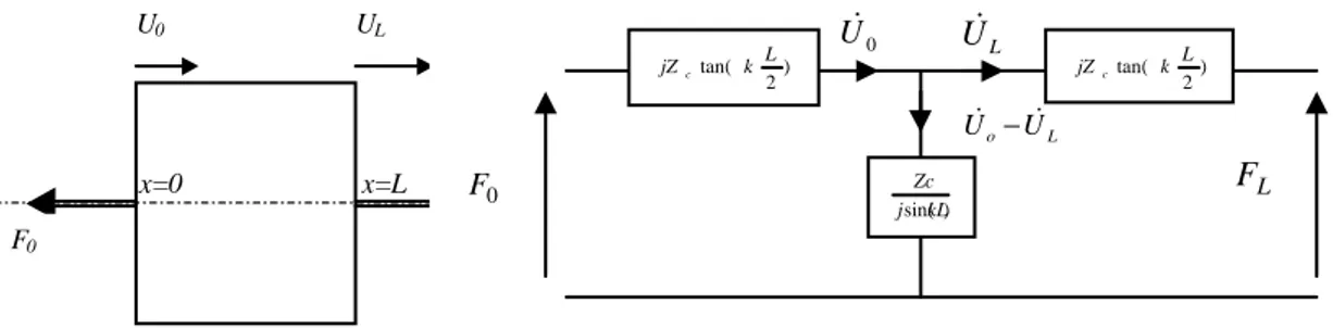
According to this approach, a non piezoelectric rod in traction/compression can be modeled
by the equivalent circuit of Fig. n° 2 where voltage F and current U& represent respectively the
effort and speed at the extremities of the rod. A transformer which expresses the
x=0 x=L F0 U0 UL Rod geometry 0 U& U&L ) 2 tan( k L jZc ) 2 tan( k L jZc ) sin(kL j Zc L o U U& − & 0 F FL
Equivalent electric circuit
Figure n° 2 : Non piezoelectric rod modeling
Modeling by equivalent circuits of the stator
Following this approach, the model of the stator of a rotating-mode motor has been
developed, which, in this case, lends itself to the calculation of the characteristic bending
magnitudes and hence the angular vibratory speed and moment at a section.
Stator’s equivalent diagram in flexion
A flexural vibration system can be modeled with a transfer matrix which connects
vibratory efforts and speeds in these two ends [6]. It is also possible to represent this matrix
by an electric circuit. For that, an elementary cross-section of a beam of section A and of
moment of inertia I is isolated in Fig. n° 3.
x x+dx T+dT T u u+du M M+dM Ψ+dΨ Ψ
Displacement is orthogonal displacement (u) or rotation angle (
Ψ
). Effort is shearing (T) or moment (M). By applying the fundamental principle of dynamics to this elementaryvolume, we get: x T t u A ∂ ∂ − = ∂ ∂ 2 2 ρ (1) And T x M t I − ∂ ∂ = ∂ Ψ ∂ 2 2 ρ (2)
The equations of the resistance of the materials give:
cI M x = ∂ ∂ψ (3) And x u AG a T T ∂ ∂ = − ψ (4)
The beams studied here are relatively short: the moment of inertia ρIdx(∂2Ψ/∂t2) of the section and the shearing effect T/(aTSG) will not be neglected [7]. We finally get:
2 2 4 2 2 4 4 4 4 ² x t u aG I c I t u S t u aG I x u cI ∂ ∂ ∂ + = ∂ ∂ + ∂ ∂ + ∂ ∂
ρ
ρ
ρ
ρ
(5)For steady-state, sinusoidal excitation and vibration the following complex notation
can be adopted: j t Ue
u = ω . The differential equation of propagation of the elastic wave then becomes: 0 ² 1 2 4 2 2 2 4 4 = − + ∂ ∂ + + ∂ ∂ U S G a I x U G a c I x U cI T T ρ ω ρ ω ρ ω (6)
This has a solution of the form:
) ( ) ( ) cos( ) sin( ) (x A k1x B k1x Csh k2x Dch k2x U = + + + (7) with: cI G a c I k T 2 ² 1 1
ω
ρ
+ + ∆ = and: cI G a c I k T 2 ² 1 2ω
ρ
+ − ∆ = where: − + + = ∆ ρ 1 ω² ² 4 ρ ω² 1 ρ ω² SG a I S cI G a c I T TThe structure of the motor is excited by ceramics, which only excite moments of
and M2 are applied at the extreme sections S1 and S2 (shearing efforts T1 and T2 are then
null).Starting from the general expression (7) of the orthogonal displacement U, the
expression of the moments is:
(
sin( ) cos( ))
(
( ) ( ))
) (x A k1x B k1x Cshk2x Dchk2x M =αM + +βM + (8) with : − = 2 1 ² k G a cI T Mρω
α
and : + = 2 2 ² k G a cI T Mρω
β
the expression of the angles is given by :
(
cos( ) sin( ))
(
( ) ( ))
) (x =αψ A k1x −B k1x +βψ Cch k2x +Dsh k2x ψ (9) with :(
)
² 1ω
ρ
α
α
ψ I SG a SG a k T T M − + = and :(
)
² 2ω
ρ
β
β
ψ I SG a SG a k T T M − + =and the expression of the efforts is written :
(
cos( ) sin( ))
(
( ) ( ))
)
(x A k1x B k1x Cch k2x Dsh k2x
T =αT − +βT + (10)
with : αT =aTSG
(
αψ −k1)
and : βT =aTSG(
βψ −k2)
By applying boundary conditions at the end sections S1 and S2 (shearing efforts T1 and
T2 null) coefficients A, B, C and D can be determined as functions of angles ψ1 and ψ2. Once
these coefficients are determined, the expression of the moments can be written:
( )
(
)
( ) ( )(
)
( cot ( /2) cot ( /2)) 2 ) 2 / tanh( ) 2 / tan( 2 ) 2 ( 2 1 2 1 2 1 2 1 1 L k anh L k an L k L k L M M T M T M T T T M T M T T α β β α α β β α ψ ψ α β β α α β β α ψ ψ ψ ψ ψ ψ + − − + + − − + = − = (11) And ( )(
)
( ) ( )(
)
( cot ( /2) cot ( /2)) 2 ) 2 / tanh( ) 2 / tan( 2 ) 2 ( 2 1 2 1 2 1 2 1 2 L k anh L k an L k L k L M M T M T M T T T M T M T T α β β α α β β α ψ ψ α β β α α β β α ψ ψ ψ ψ ψ ψ + − − + + − − + − = + = 12)They can also be rewritten in the form of:
(
1 2)
1 1 ~ ~ ) 2(− =αψ& +β ψ& −ψ&
=M L M (13) And
(
1 2)
2 2 ~ ~ ) 2(+ =−αψ& +βψ& −ψ&
=M L
With :
(
)
T T T M T M j L k L k α β β α ω α β β α α ψ ψ − − = tan( /2) tanh( /2) ~ 1 2 and(
T T)
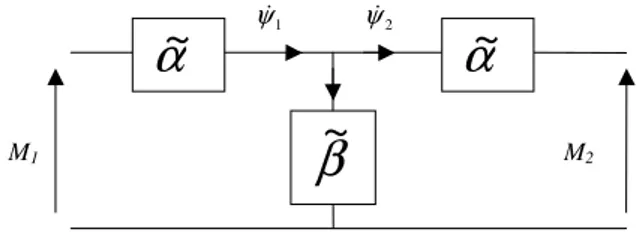
T M T M L k L k j α β β α ω α β β α β ψ ψ − + = sin( ) sinh( ) ~ 1 2These equations can be put in the form of an electric equivalent circuit (Fig. n° 4) as
for a Langevin type transducer.
β
~
α
~
α
~
M1 M2
1
ψ& ψ&2
Figure n° 4 : Electric form equivalent circuit
Stator model validation and application
This equivalent diagram represents the passive part (titanium) of the stator. The
thicknesses of the active parts (PZT) are very small. The dynamics of the stator is thus rather
well represented by this diagram. The engine functions on the first of resonance in free-free
bending. This corresponds to null moments on ends of stator (M1=M2=0).One can thus
calculate the frequency of resonance when is Zeq= β~+α~/2 null . For the geometry of stator of the figure n°2, the calculated frequency is about 104 Khz (value close to the 105 Khz
measured [1]).
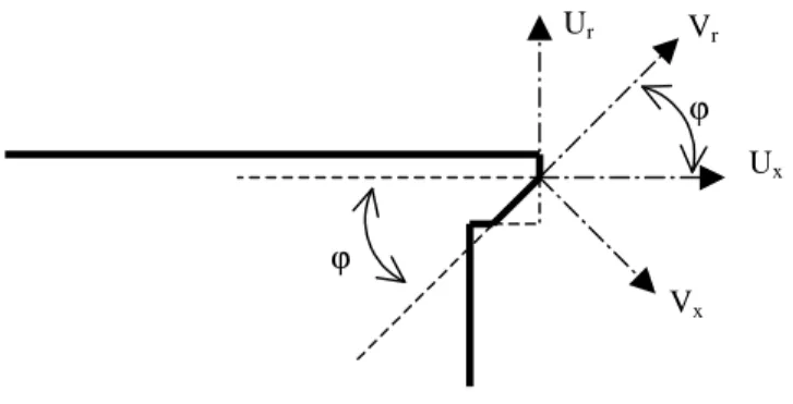
On the end surface of the stator, motion components in a cylindrical coordinate
reference can be written as [2] :
+ − + + = ) cos( ) sin( ) cos( 0 0 0 θ ω ψ θ ω θ ω θ t R t U t U U U U x r
There is a travelling wave on the circumference of the stator. It is made up of two
elliptic movements : a first, tangential and driving component, a second, radial and
contact zone (Fig. n° 5). The previous model is able to calculate this angle with geometrical
parameters of the stator.
Ur Ux Vx Vr ϕ ϕ
Figure n° 5 : Contact zone geometry
To obtain a pure travelling wave without radial parasitic movement, the Vr component
of the radial component in a reference mark V , must be null. Angle ϕ must check the following relation: 0 0 ) tan( U Rψ ϕ =
To determine the value of ϕ, relation between ψ0 and U0 should be given. By taking
again the equations described previously, one can show that:
2 2 γψ& & = U , with
(
(
(
)
(
)
)
)
( )
(
(
)
(
)
)
+ − − + − = 2 / cot 2 / cot ~ / ~ 2 / tanh 2 / tan ) ~ / ~ 2 ) ( 2 1 2 1 2 1 L k anh L k an L k L k T T T T T T α β β α α β β α α β β α γ ψ ψ And thus :γ
ϕ
= Re ) tan(For the geometry of stator of the Fig. n° 1, the angle of inclination calculated is nearly
The ceramics used are a layer of PZT thin film. The poling direction of the PZT film is
in the thickness direction and the bending vibration is generated by the length-extension
effect. The electric field component E can be assumed constant along the full length of the
ceramic. Stress and strain are thus expressed by :
3 31 1 11 1 s T d E S = E + 3 33 1 31 3 d T E D = +εT (15) With S1(y)=(dψ/dx)y L V E3 =− / (16)
Effort T can be rewritten as :
L V s d s S T E E 11 31 11 1 1 = + (19)
By integrating T1.y on the active surface of the ceramic, moment M is deduced:
dA y L V s d dA y dx d s dA y y T M =
∫∫
= E∫∫
+ E∫∫
11 31 11 1 ² 1 ) ( ψ (20)which can equally be written in the form :
NV dx d s I M E + = ψ 11 (21) with:
∫∫
= y dA I ² (22) And =∫∫
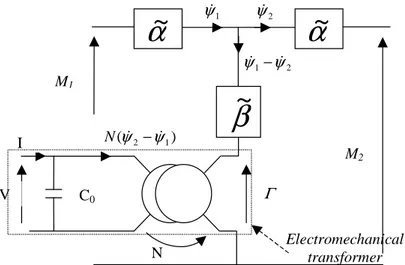
ydA L s d N E 11 31 (23)In relation (21), an expression of the form M =cI(dψ/dx)can be found again, and the
supplementary terms are equivalent to a moment Γ=NV . The electric equivalent circuit of
stator (Fig. n° 4) can be completed by a transformer which accounts for the electromechanical
conversion which takes place at the level of the ceramic. The equivalent electric diagram of
C0 Γ V I N
α
~
M1 M2 1 ψ& ψ&2 2 1 ψ ψ& − &β
~
) (ψ&2−ψ&1 Nα
~
Electromechanical transformerFigure n° 6 : Equivalent electric diagram of micromotor stator
III.
Modeling of the stator/rotor contact
To obtain the complete characteristics of the motor, it is necessary to add to the stator
model, which describes the electromechanical power conversion, an analytical modeling of
rotor/stator interaction. This stage has already been carried out for travelling wave actuators
[8] [9].
Zone of contact
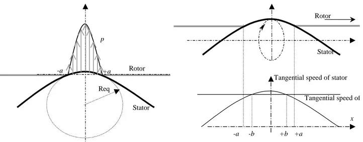
The vibrating stator is assumed to be equivalent to a portion of a cylinder and the rotor
to a plane surface. Thus the rotor/stator contact is equivalent to a cylinder/plane contact of
length 2a (Fig. n° 7). Hertz’s theory provides the length of contact and the distribution of
-a +a Req Rotor Stator p Distribution of pressure -a +a Rotor Stator -b +b x
Tangential speed of stator
Tangential speed of rotor
Distribution of tangential speeds
Figure n° 7 : Contact Stator/Rotor
Let x be the position on the external perimeter of the stator. The travelling wave
deformation y has for formula at t=0:
) / cos( ) cos( 0 0 R x R R y= ψ θ = ψ (36)
The radius of the equivalent cylinder Req takes then the expression:
0 2 2 / 1 ψ R x y Req = ∂ ∂ = (37)
The length of contact takes as value:
2 / 1 * 2 = E R L a n eq π (38) with : c F
Ln = pres , the linear load ;
rotor rotor stator stator E E E 2 2 * 1 1 1 γ −γ + −
= , the equivalent elasticity constant. The distribution of pressure p is given by:
2 / 1 2 0 1 − = a x P p with a L P n π 2 0 = (39)
The rotor speed is deduced from the tangential part Uθ of elliptic movement: ) / cos( 0 x R U U v= &θ = ω (40)
In Fig. n° 7, co-ordinate b corresponds to the point for which the local speed of the
stator is equal at the tangential speed Vr of the rotor :
) / cos( 0 b R U U
Vr = &θ = ω and .cos ( / 0 )
1 ω U V R b r − = (41)
The efforts transmitted to the rotor depend on relative speed :
• For v>Vr or –b<x<+b : positive ;
• For v<Vr or –a<x<-b ou +b<x<+a : negative.
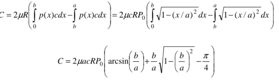
By taking a law of friction of the type dF=µ.p.sg(v−Vr)dS, torque C is calculated by:
− − − = − =
∫
∫
∫
∫
a b b a b b dx a x dx a x cRP cdx x p cdx x p R C 2 0 2 0 0 ) / ( 1 ) / ( 1 2 ) ( ) ( 2µ µ − − + = 4 1 arcsin 2 2 0 π µ a b a b a b acRP C (42)And for low speeds (b≥a), it takes the value:
R F acRP Cmax =π µ 0 =µ pres 2 (43)
Considering these expressions, the torque/speed characteristic is given by Fig. n° 8.
C Ω Cmax b>a b<a R R a U a b ) / cos( 0ω = Ω =
For the points corresponding to the b>a part of the characteristic (Figure 21.), the total
power Pθ developed in the contact for the tangential movement can be written in the
following form : dx R x a x P cU dx x v c x p P a a
∫
∫
− = = 0 2 0 0 0 cos 1 2 ) ( . ). ( 2µ µ ω θ (44) If 2 1 − a x is approximated by a x 2 cos π , Pθ becomes: dx R x a x P cU P a∫
= 0 0 0 cos 2 cos 2µ ω π θ , 2 2 0 0 2 cos − = R a a R a P cU Pπ
π
ω
µ
θ . (45)Moreover, another expression of Pθ is:
meca perte P
P
Pθ = θ + with Pmeca =Cmax.Ω (46)
In equivalent circuits, the power Pθcould be calculated by:
] [ ] [ 2 1 2 2ψ2* 2ψ2* θ ReM & Re M & P = = (47)
This expression can be rewritten according to (35), and to :
P M Re U M Re[ ]= [γ 2ψ*2]=γ * 2 2 & & (48) Then: γ ] [M2U2* Re P= & (49)
As U& , 2
ψ
&2 and M2are assumed to be co- phasal, the final expression of M2 is :2 2 0 0 2 2 cos − = = R a a R a P c U P M
π
π
γ
µ
ω
γ
( 50)dx R x a x P cU P a r
∫
= 0 0 0 sin 2 cos 2µ ω π 2 2 0 0 2 sin 2 2 − − = π π ω µ R a R a R a a P cU Pr (51)As for power Pθ, this power correspond to a tension M2 given by expression :
2 2 0 2 2 sin 2 2 − − = π π γ µ R a R a R a a P c M (52)
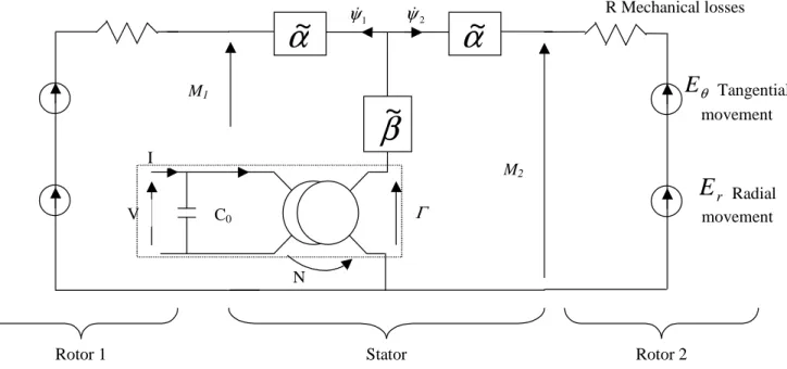
The equivalent circuit (Fig. n° 6) of the motor can thus be supplemented by adding :
A resistance R to take account of the mechanical losses within the stator (this
resistance can be replaced by the use of complex elastic constant [15]) ;
• A voltage Eθ to represent the power developed by tangential vibratory movement (Eq. (50));
• A voltage Er to represent the power developed by tangential radial movement (Eq.
(52)).
IV.
Numerical implementation of the model
Let us take the case of a micro motor made up of :
• A stator transducer (Fig. n° 1) ;
• Two rotors hold against the stator transducer at the top and the bottom by a spring.
θ
E
Tangential movement C0 Γ V I Nα
~
M1 M2 1 ψ& ψ&2β
~
α
~
R Mechanical losses Rotor 2 Stator Rotor 1 rE
Radial movementFigure n° 9 : Equivalent electric diagram of micromotor
Near frequency resonance, the dynamic part of the circuit can be represented by a RLC
equivalent circuit (Fig. n° 10).
C0 Γ
V I
N
Figure n° 10 : Equivalent RLC electric diagram of micromotor
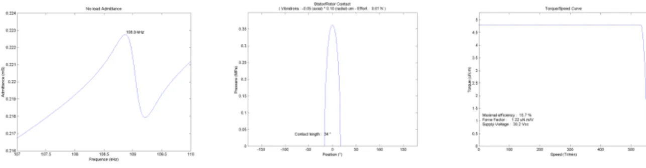
The electromechanical characteristics of this motor can be obtained : No load
admittance of the stator, torque/speed curve, the supply voltage. An example of results is
presented in fig. n° 11 (No load admittance, Contact pressure , Torque/Speed curve with
Figure n° 11 : Electromechanical caracteristics
V.
Conclusion
This article has presented a global model for cylindrical piezoelectric micromotor; it
takes into account both electromechanical conversion in the stator and mechano-mechanical
conversion between stator and rotor. The motor stator is represented here in a form very
similar to a traditional Mason circuit. The differences occur in the particular configurations of
movement, namely flexural instead of longitudinal vibrations. In the equivalent circuits,
contact between rotor and stator is represented by voltages which are functions of vibratory
speed. Useful results for design are obtained such as torque/speed curve, no load admittance,
supply voltage, stress and amplitude of vibrations. Good agreements between model and
numerical or experimental results are observed (on resonance frequency for example). This
modeling is simple to implement and would also lend itself to optimisation by analytical
References
[1] T. Morita et al., Design of a cylindrical ultrasonic micromotor to obtain mechanical
output, Jpn. J. Appl. Phys., Vol. 35 (1996), pp. 3251-3254
[2] Pin Lu et al., A kinematic analysis of cylindrical ultrasonic micromotors, Sensors and
Actuators A 87 (2001) 194-197
[3] T. Sashida , T. Kenjo, An introduction to ultrasonic motors, Clarendon Press, OXFORD,
1993.
[4] S. Ueha, Y. Tomikawa, Ultrasonic Motors, Oxford Science Publication, 1993
[5] T. Ikeda, Fundamentals of Piezoelectricity, Oxford Science Publications.
[6] G. Zhou, The performance and design of ultrasonic vibration system for flexural mode,
Ultrasonics 38 (2000), Elsevier Science, pp. 979-984
[7] S. Timoshenko, Résistance des matériaux, Dunod.
[8] Minotti P. et al., Moteur piezo-électrique à onde progressive : I. modélisation de la
conversion d’énergie mécanique à l’interface stator/rotor, Journal de Physique III., 1996,
vol. 6, n°10, p. 1315-1337
[9] J.F. Rouchon, Ph. Kapsa, The elastic contact area between a sinusoidal indentor and a
layered solid : application to calculation of ultrasonic motors performances, 29 oct.2
Nov 1995, YOKOHAMA, Japon.
[10] Messine F., Nogarede B., Lagouanelle J.-L., Optimal design of electromechanical
actuators : a new method based on global optimization, IEEE transactions on magnetics,
Notations
Ψ Rotational angle ω Frequency ρ Density γ Poisson constant µ Friction constantεS Dielectric constant for constant S
A Section area
a Half length of contact (Hertz theory)
T
a Timoshenko's coefficient
C Elastic stiffness
C0 Clamped capacity
CD Elastic stiffness for constant-D
D Electric displacement component along axe x’Ox
E Electric field component along axe x’Ox
e Piezoelectric constant
Eθ Equivalent voltage for tangential movement
Er Equivalent voltage for radiall movement
Fpres Effort on stator
G Coulomb modulus H Piezoelectric constant I Moment of inertia I Current k Wave number k33, k31 Coupling factor L Length of rod
Ln Linear load (Hertz theory)
M Bending moment
N Force factor
p Contact pressure
Pθ Power of the tangential movement
P0 Maximum pressure of contact (Hertz theory)
Pr Power of the radial movement
R Cylinder radius
Req Radius of equivalent cylinder (Hertz theory)
S Strain
T Shear force
U Displacement
![Figure n° 1 : The structure of the stator transducer [1]](https://thumb-eu.123doks.com/thumbv2/123doknet/2341756.34010/4.892.274.675.319.497/figure-n-structure-stator-transducer.webp)