HAL Id: hal-01359952
https://hal.sorbonne-universite.fr/hal-01359952
Submitted on 5 Sep 2016
HAL is a multi-disciplinary open access
archive for the deposit and dissemination of
sci-entific research documents, whether they are
pub-lished or not. The documents may come from
teaching and research institutions in France or
abroad, or from public or private research centers.
L’archive ouverte pluridisciplinaire HAL, est
destinée au dépôt et à la diffusion de documents
scientifiques de niveau recherche, publiés ou non,
émanant des établissements d’enseignement et de
recherche français ou étrangers, des laboratoires
publics ou privés.
Size, Gain and Bandwidth trade-offs for Wideband
Diamond Dipole with AMC reflector
Chetan Joshi, Anne Claire Lepage, Julien Sarrazin, Xavier Begaud
To cite this version:
Chetan Joshi, Anne Claire Lepage, Julien Sarrazin, Xavier Begaud. Size, Gain and Bandwidth
trade-offs for Wideband Diamond Dipole with AMC reflector. 2nd International Conference on
Communi-cation Systems , Oct 2015, Pilani,Rajasthan, India. �10.1063/1.4942733�. �hal-01359952�
Size, Gain and Bandwidth trade-offs for Wideband
Diamond Dipole with AMC reflector
Chetan Joshi
1, a), Anne Claire Lepage
1, Julien Sarrazin
2and Xavier Begaud
11
Institut Mines-Télécom,Telecom Paristech-LTCI CNRS, UMR 514, Paris, France 2 L2E Dept., Université Pierre et Marie Curie (UPMC), 75005 Paris, France
a)Corresponding author: [email protected]
Abstract. Compact and directive ultra-wideband antennas are required in variety of applications. Directional wideband
antennas can be designed by using a reflector to redirect the energy back in half space and increase the gain. Use of artificial magnetic conductors (AMC) as reflectors for antennas allows reduction in the thickness of an antenna using traditional perfect electrical conductors (PEC) reflectors. The lateral size of the reflector also has an important effect on the antenna performance. In this paper, we study the trade-offs involved in the design of an AMC used as a reflector for broadband diamond dipole antenna by simulating various sizes of the reflector.
INTRODUCTION
The wideband antennas can be used in a variety of application. For example, such antennas may be used to locate people trapped in building rubble in an earthquake like scenario. Another application may include medical imaging. Such applications may require an antenna to be unidirectional with high gain. High gain planar wideband antennas can be envisaged for these applications as they present the advantage of low profile and small size.
In order to design directional planar antennas, reflectors are used. A traditional reflector made using PEC, reverses the phase of the electric field of the incident wave sees. Therefore, such a reflector needs to be placed at a distance of quarter wavelength (λ/4). Such an antenna has a thick profile and a limited bandwidth of operation. A way to avoid the problem of thickness is to use Artificial Magnetic Conductors (AMC) as antenna reflector.
AMC’s are usually surfaces made of periodically printed metallic patches printed on a dielectric substrate backed by a metallic ground plane. AMC’s present the advantage of 0° difference between the phase of the incident and reflected waves at a fixed frequency at normal incidence, and the frequency band in which the phase of the reflected waves is ±90° is said to be the operational bandwidth of the AMC. An AMC reflector can, therefore, be placed very close to the antenna in this frequency band to achieve a low profile for a reflector based antenna. Further details about AMC can be considered in [1].
Use of AMC reflectors with broadband antennas allows reduction in their profile. However, reduction of lateral size of reflectors is also an important design aspect for different applications. AMC/EBG reflectors can be used with different planar wideband dipoles. Most used geometries of wideband antennas are bow-tie antenna and diamond dipole antenna. In [2], the role of the size of the Electromagnetic Band Gap (EBG) reflector has been studied vis-a-vis a bow-tie antenna. It has been reported that as the size of the reflector becomes smaller, the bandwidth of the radiating structure is reduced, and the bandwidth shifts higher in frequency. It is also said that radiation pattern of such an antenna is distorted in lower and higher frequencies of the band. In [3], a diamond dipole antenna is studied over an AMC reflector plane. It is said that using larger AMC sizes can improve the impedance bandwidth, but it has little effect of the gain of the antenna.
In this article, a planar diamond dipole antenna is first presented. This antenna is then studied with different sizes of an AMC reflector, which is designed to work in the frequency range of the antenna. We draw conclusions about the trade-offs involved in size, gain and bandwidth of the antenna.
BASIC DESIGN OF ANTENNA & AMC REFLECTOR
The antenna used for this study is a diamond dipole antenna as shown in Fig. 1 (a). The antenna dimensions are L = 9 mm, S = 0.3 mm, a = 1.5 mm & b = 3 mm. The antenna is designed on CuClad Substrate (h = 1.58 mm, εr = 2.5, tan δ = 0.0018). The unit cell of AMC consists of a square metallic patch of side 7.4 mm, each separated by a distance of 1 mm. The substrate used is FR4 Epoxy (h = 3.2 mm, εr = 4.1, tan δ = 0.02). Further details on the design can be consulted in [4]. On simulating using unit cell boundary conditions in CST Microwave StudioTM, the in-phase reflection frequency of this unit cell is f0 = 5 GHz. This boundary condition assumes an infinite repetition of unit
cells in the lateral plane. However, in practical applications, the AMC reflector will be of finite size, such as shown in Fig. 1(b). This is discussed in the next section.
(a) (b)
FIGURE 1. (a) Planar diamond dipole antenna. (b) Antenna & 6x6 AMC reflector.
ANTENNA WITH DIFFERENT SIZES OF AMC REFLECTOR
In order to better understand the effect that the size of the reflector has on the characteristics of the diamond dipole antenna, four different sizes of AMC are simulated: 6x6, 8x8, 10x10 and 12x12. A gap of 2 mm is kept between the antenna substrate and the AMC reflectors. The antenna is excited using a discrete port in CST Microwave Studio. The results are shown in Fig. 2.
(a) (b)
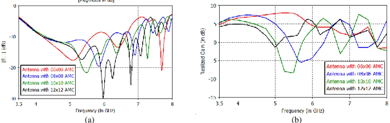
FIGURE 2. (a) Comparison of impedance bandwidth (|S11|<-10 dB) of antenna with four different sizes of reflectors. (b)
Comparison of corresponding broadside gains.
As seen in Fig. 2(a), the impedance bandwidth (|S11|<-10 dB) of the antenna increases with the size of AMC reflector. For a reflector in 6x6 arrangement of metallic patches, the bandwidth is 1.47 GHz (4.19-5.66 GHz),
whereas for a reflector in 12x12 arrangement of metallic patches, the bandwidth is 2.97 GHz (4.19 -7.16 GHz). It is also to be noted that unlike [2], use of smaller reflector does not result in shift towards higher frequencies. In fact, for all the cases, the lower frequency stays constant around 4.20 GHz. As the size of the reflector increases, the upper bound of the bandwidth shifts higher in frequency. This may be attributed to resonances occurring at higher frequencies in the AMC reflector itself. Thus, when looking to increase the bandwidth of the antenna, increasing the size of the reflector is an option.
However, the gain obtained in broadside direction is also an important criterion of antenna performance. Broadside gains of the antenna and the four reflectors have been plotted in Fig. 2(b). It is seen that a 6x6 reflector maintains an overall high gain in the broadside direction in all the frequency range, with a maximum of 8 dB at 5.35 GHz. As the size of the reflector increases, the radiation pattern degrades and a visible reduction in broadside gain is observed. For 8x8 reflector, a broadside gain minimum (-5.4 dB) is obtained at 5.7 GHz. For 10x10 reflector, the broadside gain minimum (-8.3 dB) is obtained at 5.49 GHz. Similarly, for a 12x12 reflector, the minimum (-1.37 dB) is observed at 5 GHz. Thus as the size of the reflector increases, the radiation pattern is degraded lower and lower in the bandwidth of the antenna.
It is seen that a trade-off is involved when making a choice for the size of the reflector plane. If the application requires a wideband antenna without strict requirements of high gain, a diamond dipole antenna with a large AMC reflector plane can be used. But, if the application requires high gain antenna, then a smaller AMC reflector should be used, giving up the advantage offered by larger AMC reflectors.
CONCLUSION
In this paper, the effect of size of the AMC reflector on a diamond dipole antenna has been discussed. The study indicates that a trade off exists when using this particular antenna with AMC reflectors. For smaller reflectors, the antenna has comparatively smaller bandwidth, but presents high gain in the broadside direction. However, as the size of the reflector increases, the impedance bandwidth of the antenna increases. This has been attributed to resonances occurring in higher frequencies in the AMC reflector itself. However, this comes at the sacrifice of broadside gain of the antenna in the frequency bandwidth, which degrades further lower down in the bandwidth each time on increasing the size of the reflector.
ACKNOWMEDGEMENTS
This work is supported by the NanoDesign project funded by the IDEX Paris-Saclay, ANR-11-IDEX-0003-02.
REFERENCES
1. D. Sievenpiper, “High Impedance Electromagnetic Surfaces,” Ph.D. thesis, University of California, 1999. 2. S.R. Best and D.L. Hanna, IEEE Antenn. Propag. Mag., Vol. 50, No. 6, 52-64 (December 2008).
3. L. Akhoondzadeh-Asl, D.J. Kern, P.S. Hall and D.H. Werner, IEEE Trans. Anten. Propag., Vol. 55, No 9, 2426-2434 (December 2007).
4. A.C. Lepage, J. Sarrazin and X. Begaud, “Wideband Directive Antennas with High Impedance Surfaces,” in