Status of the ARGOS ground layer adaptive optics system
Wolfgang Gässler
*a, Sebastian Rabien
b, Simone Esposito
c, Michael Lloyd-Hart
d, Lothar Barl
b, Udo
Beckmann
e, Thomas Bluemchen
a, Marco Bonaglia
c, José Luis Borelli
a, Guido Brusa
f, Joar Brynnel
f,
Peter Buschkamp
b, Lorenzo Busoni
c, Luca Carbonaro
c, Claus Connot
e, Richard Davies
e, Matthias
Deysenroth
e, Olivier Durney
d, Richard Green
f, Hans Gemperlein
b, Victor Gasho
d, Marcus Haug
b,
Pete Hubbard
d, Sebastian Ihle
g, Martin Kulas
a, Reinhard Lederer
b, Jason Lewis
d, Christina Loose
b,
Michael Lehmitz
a, Jamison Noenickx
d, Edmund Nussbaum
e, Gilles Orban de Xivry
b, Diethard
Peter
a, Andreas Quirrenbach
h, Matt Rademacher
d, Walfried Raab
b, Jesper Storm
i, Christian Schwab
h,
Vidhya Vaitheeswaran
d, Julian Ziegleder
ba
Max-Planck-Institut für Astronomie, Koenigstuhl 17, 69117 Heidelberg, Germany
bMax-Planck-Institut für extraterrestrische Physik, Garching, Germany
c
INAF - Osservatorio Astrofisico di Arcetri. Florence, Italy
dThe Univ. of Arizona, Tucson, Arizona, USA
eMax-Planck-Institut für Radioastronomie, Bonn, Germany
fLarge Binocular Telescope Observatory, Tucson Arizona, USA
g
PNSensor GmbH, Munich, Germany
hLandessternwarte Heidelberg, Germany
iLeibniz-Institut für Astrophysik Potsdam, Germany
ABSTRACT
ARGOS the Advanced Rayleigh guided Ground layer adaptive Optics System for the LBT (Large Binocular Telescope) is built by a German-Italian-American consortium. It will be a seeing reducer correcting the turbulence in the lower atmosphere over a field of 2' radius. In such way we expect to improve the spatial resolution over the seeing of about a factor of two and more and to increase the throughput for spectroscopy accordingly. In its initial implementation, ARGOS will feed the two near-infrared spectrograph and imager - LUCI I and LUCI II.
The system consist of six Rayleigh lasers - three per eye of the LBT. The lasers are launched from the back of the adaptive secondary mirror of the LBT. ARGOS has one wavefront sensor unit per primary mirror of the LBT, each of the units with three Shack-Hartmann sensors, which are imaged on one detector.
In 2010 and 2011, we already mounted parts of the instrument at the telescope to provide an environment for the main sub-systems. The commissioning of the instrument will start in 2012 in a staged approach. We will give an overview of ARGOS and its goals and report about the status and new challenges we encountered during the building phase. Finally we will give an outlook of the upcoming work, how we will operate it and further possibilities the system enables by design.
Keywords: Ground Layer Adaptive Optics, Laser Guide Star, Large Binocular Telescope
1. INTRODUCTION
In November 2006 a brainstorming workshop in Florence about possible laser upgrades of the LBT1 adaptive optics
system2 paved the road for ARGOS. The outcome of this workshop defined a mission, which then was approved by the
LBT board.
*[email protected] ; phone +49-6221-528277; fax +49-6221-528
Adaptive Optics Systems III, edited by Brent L. Ellerbroek, Enrico Marchetti, Jean-Pierre Véran, Proc. of SPIE Vol. 8447, 844702 · © 2012 SPIE · CCC code: 0277-786/12/$18 · doi: 10.1117/12.926167
Proc. of SPIE Vol. 8447 844702-1
The mission requested a design of a laser and wavefront sensor system, which is exploring the wide field capabilities of the LUCI instrument, a near-infrared imager and multi-object spectrograph. Fulfilling following requirements:
• Promptly implementation of a ground layer adaptive optics system. • The system must have operability significant over median seeing.
• The system must be reliable, low maintenance and a reasonable cost system. • The system must minimize the impact to telescope and LUCI3.
• The design should identify upgrade paths to at least on-axis diffraction limited performance4.
In May 2007, with the kick off meeting in Heidelberg, a consortium of nearly all partner institutions of the LBT started to work on this task. This finally resulted in the ARGOS instrument, which is now close to installation at the telescope. As the system was already presented several times we will not go into detail of the science capabilities or performance simulation, which can be found in proceedings of previous conferences5,6.
2. ARGOS IN A NUTSHELL
2.1 Overview
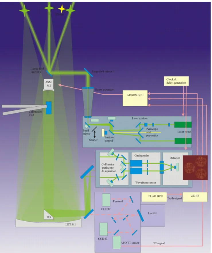
ARGOS has two independent units one for the right and the other for the left side of the LBT. A scheme of one unit is shown in Figure 1. Each unit consists of:
• a laser system7
• a launch system • a wavefront sensor8,9,10
• TT and Truth sensor • a calibration unit11
The laser system has three Rayleigh lasers at 532nm wavelength. The lasers are separated and can be adjusted with a periscope system to the 2’ radius of the field on sky. Cameras re-image the pupil and the focal plane inside the laser system box monitoring differential flexure of the laser heads. A common tip tilt mirror for all lasers compensates telescope vibrations introduced to the launch system. The vibrations are measured with accelerometers placed on the launch mirrors and compensated in feed forward12.
The launch system comprises of the exit window out of the laser box, a focus system to adjust the spot size at the 12km projection distance and two launch mirrors, folding the beam to the back of the adaptive secondary and launch them from there to sky.
The Shack-Hartmann wavefront sensor is fed over a dichroic with the laser light while the light above 600nm is transmitted to the science instrument and the natural guide star wavefront sensor. All three lasers are imaged through one lenslet array on one low noise detector from PNSensor. Some fast steering mirrors compensate the Laser Guide Star jitter directly from the wavefront measurements. The laser guide stars are acquired with individual patrol cameras, which see light when the laser beam is not pointed into the 2.35” radius aperture hole of the wavefront sensor. Pockels cells are used to shutter the laser light. They are synchronized electronically with an 80,6usec delay to the lasers, opening at a 10kHz repetition rate for 2usec corresponding to 300m range gate.
The existing natural guide star pyramid wavefront sensor board is extended with a quad cell of APDs to measure the TipTilt signal. Some of the light is split to the pyramid wavefront sensor to measure the non common path error and continuously update the slope offsets.
To be able to test and optimize the system off sky a calibration unit is placed below the prime focus. An on-axis source launched from the center of the adaptive secondary is reflected on the front asphere of the unit to the science instrument and the natural guide star wavefront sensor. Three off-axis beams are propagated through a hologram to be imaged on the Shack-Hartman wavefront sensor.
Proc. of SPIE Vol. 8447 844702-2
Figure 1 shows the scheme of ARGOS with its major systems, starting from bottom to top the Tip-Tilt and Truth sensor, the wavefront sensor, the laser system and the launch system reaching into the telescope and finally, below the prime focus, the calibration unit.
Proc. of SPIE Vol. 8447 844702-3
2.2 Goals
ARGOS is not intended to provide diffraction limited performance but to improve the natural seeing to up to 2” by a factor 2-3 in FWHM over the 4’ squared field of LUCI. This leads to a corresponding gain in flux in the 0.25” slits, which decreases the observing time by a factor 4-9. One way to look at this is shown in Figure 2. In principal the seeing curve is moved in average to the better and the mean seeing for an observation improves.
Figure 2 shows a seeing curve of Mt Hopkins and a curve which is folded with the ARGOS performance we received from our simulations. The mean seeing improves from about 0.63” to 0.35”.
3. MANAGING COMPLEXITY: THE ITERATIVE AND STAGED APPROACH
ARGOS is a system, which is highly distributed over the telescope. The testing of all the units together can only be done at the telescope, as it is not possible to have all the components including the adaptive secondary somewhere integrated in a laboratory. This is due to the fact that:• The natural guide star unit, which is used as Truth and TT sensor, is already integrated and in operation at the LBT
• The deformable adaptive secondary is already in operation at the LBT
• The integrated test of laser and launch system together would imply a 12km long laboratory or needs a telescope to test with on sky
An additional managerial challenge is the structure of the consortium, where hardware units are developed and integrated at different places than the software development of the overall instrument. This complexity is handled by an iterative and staged approach. The hardware is assembled by sub-systems or units of the instrument and installed at the telescope in incremental steps. The calibration unit is already delivered to LBT. The TT and Truth sensor will be installed coming summer. The launch and laser system will be installed coming fall and winter and than tested with an acceptance milestone: launch on sky. The last part will be the laser guide star wavefront sensor with the final milestone: closing the
Proc. of SPIE Vol. 8447 844702-4
loop on sky. All the systems have sub-system acceptance procedures, where their interfaces and functionalities are tested to that extend, which is possible with the stand alone sub-system. This includes flexure and temperature testing of the hardware. The software development is done in an iterative way. A detailed report on this approach can be found in Kulas13. Starting only with providing the most important hardware functionality of a device on a software level, the
sub-system integration provides final information on needs of functionalities. This demands a good structuring of the instrument sub-systems and a maximum on definition of sub-system functionalities in advance, which was done with the Final Design Review. The functionalities grow and change with integration and the better understanding of the behavior of the hardware. As the hardware selection and the ideas how the system should work is developed with the sub-system responsible partner team, such approach needs that each team feels also responsible to define the functionalities and has some capability to develop algorithms and operational procedures in a scripting environment provided by the software development team. This information is than transported by an analyst, who has an understanding of the full instrument to the software engineers, which than only focus on the software implementation. With only limited resources, as quite usual for instrumentation projects, the advantage of the iterative and staged approach is that the complexity is broken down in units, which are easier to understand, and in time, where one can focus on certain aspects step by step.
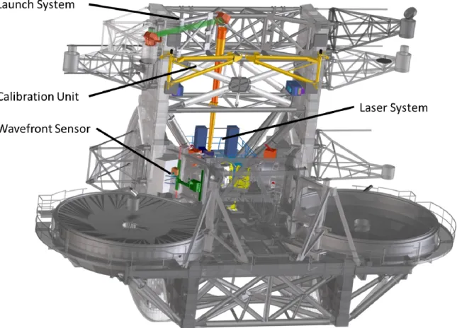
Figure 3 shows the ARGOS components as they will be distributed over the telescope structure.
4. SUB-SYSTEM STATUS
4.1 Laser System
Currently the laser system gets integrated at the MPE in Garching, Germany. Both laser boxes for left and right are close to final assembly. The functionality and flexure test will be done on a stand, which can be tilted. The lasers are aligned with a mask in an intermediate focal plane to an on-axis alignment laser. First, functionality software tests of the laser
Proc. of SPIE Vol. 8447 844702-5
state machine are procured positively. After the flexure of the system is understood better, one can finalize the state machine, which includes an automated flexure compensation loop. An engineering GUI (Graphical User Interface), which contains all the functionalities needed is currently used for the testing and will be optimized for commissioning purposes.
Figure 4: Upper left: ARGOS team members during assembly of the second laser box in the clean booth. Upper right: The assembled optics in the ARGOS laser box without the lasers. Lower left: The ARGOS test stand. Lower right: The ARGOS laser system engineering GUI.
4.2 Launch System
Currently the launch system is integrated at the University of Arizona in Tucson. All folding mirrors are polished and coated. The mounting structures of the first fold mirror is finished, the one of the second fold mirror on top of the adaptive secondary has still to be manufactured. Mid of July the combined actuator movement of the motorized first fold mirror over the full temperature range will be performed. This is the last test which is missing before going to the telescope.
Proc. of SPIE Vol. 8447 844702-6
Figure 5: Left: One of the folding mirrors with its mount on the test stand to measure the optical flatness with an interferometer. Right: One of the folding mirrors on the desk for the overall reflectivity measurement.
4.3 Wavefront Sensor System
The wavefront sensor system gets assembled at the Osservatorio Astrofisico di Arcetri in Florence, Italy. The optics of the first unit is assembled and aligned and initial closed loop tests with a MEMS from Boston Micromachines are performed. In such way the alignment can be tested and can be optimized.
Figure 6: Left: Assembly of the first wavefront sensor unit. Right: First closed loop results. Most right PSF is the reference source the other show the optical performance of the three light paths. The middle of the three seems to be misaligned.
Proc. of SPIE Vol. 8447 844702-7
4.4 TT and Truth Sensor System
The TT and Truth Sensor System is an extension of the existing natural guide star sensor unit. Therefore the main part is already at the telescope in operation. The remaining parts are the APDs, which are already at the Leibniz-Institut für Astrophysik Potsdam for testing, some mechanics, which are in manufacturing, a small shutter, which currently is tested and optimized also at Potsdam and the lenslet array with fiber, where the first trial failed specification as claimed by the vendor.
4.5 Calibration System
The calibration unit, which is built at MPIA in Heidelberg, is already partially delivered to the telescope. The swing arms have been mounted last summer and functionality tests have been performed. The very challenging optics with a hologram and the mechanics out of Invar is in manufacturing and will be assembled this summer. The final alignment and installation will be far before delivery of the wavefront sensors to telescope well in time.
5. CHALLENGES ENCOUNTERED
As one of the main goal of our mission is a promptly implementation we had to go for an agile building approach. We followed the usual project phases and review process but we also tried to speed up long lead items with an early procurement and minimization of prototyping. But as usual also not so critical items show problems or are out of specification. Therefore, continuous and immediate testing after arrival is important. In this chapter we describe some of the problems we encountered. How some of them slipped through the review process and how we try to stay in time.
5.1 Dichroics
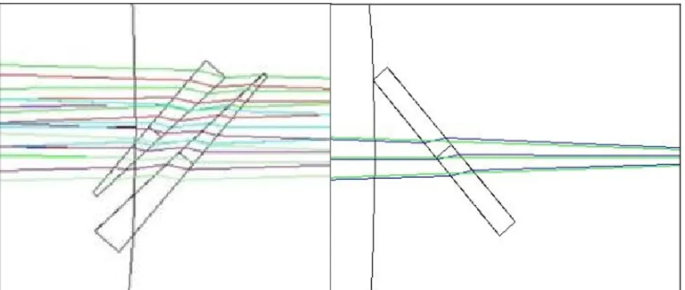
The dichroics in front of the science instrument are a large elliptical piece of glass with 300mm in the minor and 400mm in the major axis. The dichroic needs not only a very special high performance coating to split the light in the right way but also compensates for the focal shift introduced by its thickness. To avoid flexure effects a certain thickness is needed. The original final design was a 40mm think Infrasil dichroic with a cylinder to compensate the distortion. The relative remaining distortion was not larger than the distortion introduced by the LUCI internal optics. But as the compensation is not symmetric and the dichroic stays fix to the de-rotating instrument behind the absolute values of the distortion introduced a movement of objects in the outer field. Even this was found after final design it was luckily encountered still early enough before going to the telescope. Several alternatives, where discussed by a tiger team and the most promising selected. The reason it could slip through the review process was that no absolute values were given and the optics was detached from the overall system analysis. The permanent re-evaluation of the system and how it should work helped to find the flaw. A tiger team, which was immediately put in place, accelerated the resolution of the problem.
Proc. of SPIE Vol. 8447 844702-8
Figure 7: Left: Air spaced achromate. Right. Thin dichroic with only 20mm thickness and low incident angle.
5.2 Laser
The lasers have been delivered and tested already since one and a half year. They showed the maximum power but after some dispute with the vendor it was clear the M2 specification was not reached. This was fixed by the vendor but an
additional decline in maximum power with time is still unsolved. The current loss in maximum power would not stop the system from working but if it decreases further with time it will. A reduction in power will be accepted if this will get on the critical path. Further, testing can than go on with the spare unit.
5.3 Pockels cell
During temperature cycling of the Pockles cells we encountered, that the mechanical mounting of the crystal produces a too strong strain onto the optics, resulting in reduced performance. The mechanical design needed to be changed and new mounts were required. Some of the cells where used for testing of the wavefront sensor the others have been re-worked. With parallelizing the work the schedule was not delayed.
5.4 CCD
The ADC of the readout electronic introduced some artificial noise. To speed up the electronic development and to have a backup another ADC board was ordered by a different company. This competitive approach is speeding up and is redundant.
6. UPCOMING WORK AND OPERATIONAL ASPECTS
Until end of the year we try to get the laser and launch system installed on the telescope and launch the lasers on sky. This step will be done in a very interactive way with engineering GUIs combining the main functionalities needed. Early next year the wavefront sensor will follow and the commissioning with closed loop on sky will be done, still in an interactive fashion. Step by step the system will then be automized. Finally, the goal is to have as for the current natural guide star system at the LBT an automatic procedure to acquire the guide star and optimize the loop parameters.
As ARGOS is a seeing reducer it would be nice to have it accessible on the fly for any observation. One of the obstacles is the clearance of the observation by space command. This is time and target dependent and has to be done in advance. Therefore, a submission of the targets few days before the observation is necessary. Currently this is not supported by LBT but will be changed for ARGOS and can than be extended to all LUCI observations.
7. CONCLUSION
ARGOS is on its way to the telescope. The sub-system are getting integrated and tested. Currently the team is on a good track to accomplish the mission goals providing a wide field correction for LUCI in a decent time line. Therefore, several managerial approaches have been used:
• Staged • Iterative • Agile
All this is only possible with a highly motivated team, well structured and with clear decisions from the top, which compromise performance for time or time for performance always depending on case and priority.
Proc. of SPIE Vol. 8447 844702-9
The first parts of ARGOS are already installed on the telescope, namely the laser platform, the calibration swing arms. This summer the next sub-systems to be installed are the launch telescope and the Tip-Tilt optomechanics followed in fall and winter by the laser system and the first launch on sky. Early next year the wavefront sensor will follow. The team plans on a handover to the community by 2014 providing a fully automized wide field seeing reducer.
REFERENCES
[1] Hill, John M.; Green, Richard F.; Slagle, James H.; “The Large Binocular Telescope” Proc. SPIE 6267, 626 (2006)
[2] Esposito, S.; Riccardi, A.; et. al.; “Large Binocular Telescope Adaptive Optics System: new achievements and perspectives in adaptive optics” Proc. SPIE 8149, 10 (2011)
[3] Seifert, Walter; Appenzeller, Immo; et. al.; “LUCIFER: a Multi-Mode NIR Instrument for the LBT” Proc. SPIE 4841, 962-973 (2003)
[4] Hart, Michael; et. al.; “Diffraction-limited upgrade to ARGOS: the LBT's ground-layer adaptive optics system” Proc. SPIE 7736, 11 (2010)
[5] Rabien, S.; et. al. ; “ARGOS: the laser guide star system for the LBT” Proc. SPIE 7736, 12 (2010)
[6] Hart, M.; Rabien, S.; et. al.; “Status report on the Large Binocular Telescope's ARGOS ground-layer AO system” Proc. SPIE 8149, 11 (2011)
[7] Loose, C; et. al.; “Testing and integrating the laser system of ARGOS, the Ground Layer Adaptive Optics for LBT” " Proc. SPIE 8447, (2012)
[8] Bonaglia et. al., "Laboratory characterization of the ARGOS laser wavefront sensor" Proc. SPIE 8447, (2012) [9] Bonaglia, Marco; “Design of the wavefront sensor unit of ARGOS, the LBT laser guide star system”
arXiv1203.5081B, (2012)
[10] de Xivry, G. O. ,"A testbench for ARGOS: integration of sub-systems and validation of the wavefront sensing" Proc. SPIE 8447, (2012)
[11] Schwab, Christian; Gassler, Wolfgang; Peter, Diethard; Blumchen, Thomas; Aigner, Simon; Quirrenbach, Andreas “Design of an holographic off-axis calibration light source for ARGOS at the LBT” 1st AO4ELT conference - Adaptative Optics for Extremely Large Telescopes, (2010)
[12] Diethard Peter, Wolfgang Gässler, José Luis Borelli, Lothar Barl, Sebastian Rabien, “Vibration compensation for the ARGOS laser launch path” Proc. SPIE 8447, (2012)
[13] Kulas, M.; et. al. “Instrument control software development process for the multi-star AO system ARGOS” Proc. SPIE 8451, (2012)
Proc. of SPIE Vol. 8447 844702-10