eScholarship provides open access, scholarly publishing services to the University of California and delivers a dynamic research platform to scholars worldwide.
Adaptive Optics for Extremely Large
Telescopes 4 – Conference Proceedings
Peer Reviewed
Title:
Development of an ELT XAO testbed using a self referenced Mach-Zehnder wavefront sensor
Journal Issue:
Adaptive Optics for Extremely Large Telescopes 4 – Conference Proceedings, 1(1)
Author:
Delacroix, Christian
, Centre de Recherche Astrophysique de Lyon (CRAL)
Loupias, Magali
, Centre de Recherche Astrophysique de Lyon (CRAL)
Langlois, Maud
, Centre de Recherche Astrophysique de Lyon (CRAL)
Tallon, Michel
, Centre de Recherche Astrophysique de Lyon (CRAL)
Thiébaut, Eric
, Centre de Recherche Astrophysique de Lyon (CRAL)
Publication Date:
2015
Permalink:
http://escholarship.org/uc/item/6h92z4q4
DOI:
https://doi.org/10.20353/K3T4CP1131619
Keywords:
extreme adaptive optics, high order wavefront sensing, Mach-Zehnder interferometer;high
dynamic range, spatial light modulator, deformable mirror
Local Identifier(s):
ao4elt4_31619
Abstract:
Extreme adaptive optics (XAO) has severe difficulties meeting the high speed (>1kHz), accuracy
and photon efficiency requirements for future extremely large telescopes. An innovative high
order adaptive optics system using a self-referenced Mach-Zehnder wavefront sensor (MZWFS)
allows counteracting these limitations. In addition to its very high accuracy, this WFS is the most
robust alternative to segments gaps and telescope spiders which can result in strong wavefront
artifacts. In particular in XAO systems when the size of these gaps in the wavefront measurement
is comparable to the sub aperture size, loss in performance can be very high. The MZWFS
estimates the wavefront phase by measuring intensity differences between two outputs, with a
λ/4 path length difference between its two legs, but is limited in dynamic range. During the past
few years, such an XAO system has been studied by our team in the framework of 8-meter class
telescopes. In this paper, we report on our latest results with the XAO testbed recently installed
eScholarship provides open access, scholarly publishing services to the University of California and delivers a dynamic research platform to scholars worldwide.
in CRAL laboratory, and dedicated to high contrast imaging with 30m-class telescopes (such as
the E-ELT or the TMT). A woofer-tweeter architecture is used in order to deliver the required high
Strehl ratio (>95%). It consists of a 12x12 deformable mirror (DM) and a 512x512 Spatial Light
Modulator (SLM) characterized both using monochromatic and polychromatic light. We present
our latest experimental results, including components characterization, close loop performances
and sensitivity to calibration errors. This work is carried out in synergy with the validation of fast
iterative wavefront reconstruction algorithms and the optimal treatment of phase ambiguities in
order to mitigate the dynamical range limitation of such a wavefront sensor.
Copyright Information:
All rights reserved unless otherwise indicated. Contact the author or original publisher for any
necessary permissions. eScholarship is not the copyright owner for deposited works. Learn more
at
http://www.escholarship.org/help_copyright.html#reuse
*e-mail at [email protected]
Development of an ELT XAO testbed using a self referenced
Mach-Zehnder wavefront sensor
Magali Loupias*, Maud Langlois, Eric Thiébaut,
Christian Delacroix, Jonathan Leger, Louisa Adjali and Michel Tallon
Université de Lyon, Lyon, F-69003, France; Université Lyon 1, Observatoire de Lyon, 9
avenue Charles André, Saint-Genis Laval, F-69230, France; CNRS, UMR 5574, Centre de
Recherche Astrophysique de Lyon; Ecole Normale Supérieure de Lyon, Lyon, F-69007,
France
ABSTRACT
Extreme adaptive optics (XAO) has severe difficulties meeting the high speed (>1kHz), accuracy and photon efficiency requirements for future extremely large telescopes. An innovative high order adaptive optics system using a self-referenced Mach-Zehnder wavefront sensor (MZWFS) allows counteracting these limitations. In addition to its very high accuracy, this WFS is the most robust alternative to segments gaps and telescope spiders which can result in strong wavefront artifacts. In particular in XAO systems when the size of these gaps in the wavefront measurement is comparable to the sub aperture size, loss in performance can be very high. The MZWFS estimates the wavefront phase by measuring intensity differences between two outputs, with a λ/4 path length difference between its two legs, but is limited in dynamic range. During the past few years, such an XAO system has been studied by our team in the framework of 8-meter class telescopes. In this paper, we report on our latest results with the XAO testbed recently installed in CRAL laboratory, and dedicated to high contrast imaging with 30m-class telescopes (such as the E-ELT or the TMT). A woofer-tweeter architecture is used in order to deliver the required high Strehl ratio (>95%). It consists of a 12x12 deformable mirror (DM) and a 512x512 Spatial Light Modulator (SLM) characterized both using monochromatic and polychromatic light. We present our latest experimental results, including components characterization, close loop performances and sensitivity to calibration errors. This work is carried out in synergy with the validation of fast iterative wavefront reconstruction algorithms and the optimal treatment of phase ambiguities in order to mitigate the dynamical range limitation of such a wavefront sensor.
Keywords: extreme adaptive optics, high order wavefront sensing, Mach-Zehnder interferometer, high dynamic
range, spatial light modulator, deformable mirror
1. INTRODUCTION
The direct detection and characterization of exoplanetary systems and debris disks around nearby stars requires achieving high-contrast imaging capabilities, very close to the host star. Recently deployed new instruments (Palomar/P1640,1 Gemini/GPI,2 and VLT/SPHERE3,4) use extreme adaptive optics (XAO) to compensate for the atmospheric turbulence, and coronagraphy to attenuate the signal of the host star. Commonly used wavefront sensors (WFS) such as Shack-Hartmann and Curvature are very robust and flexible, but poorly suited to high sensitivity wavefront measurements5. The conventional Shack Hartmann concept suffers from the noise propagation effect, due to the wavefront reconstruction step and is limited to its sub pupil for high frequencies aberrations. Other WFS concepts exist, that maintain a very high sensitivity, constant at all separations, across a wide range of spatial frequencies, such as Mach-Zehnder WFS6-8, Zernike WFS9,10, pyramid WFS11. For these WFS concepts, the noise propagation is low, and both low-order and high-order terms can be corrected very efficiently. Furthermore high order frequencies artefacts introduced by the telescope spider and segmented pupil, drastically increase the noise in the reconstructed wavefront of a classical Shack-Hartmann. The Mach-Zehnder WFS, given a few hypotheses, can minimize the wavefront reconstruction step and be more robust to these artefacts. High sensitivity wavefront measurements are mandatory to detect Earth-like planets with future extremely large telescopes (ELTs).
In this paper, we present the setup and calibration of an experimental test bench at CRAL (Centre de Recherche Astrophysique de Lyon), dedicated to the study of XAO for 30m-class ELTs. The Mach-Zehnder Wavefront Sensor (MZWFS) principle used in our set-up and the demanding performances of Adaptive Opitcs for ELT’s
are detailed and compared in section 2. In Section 3, we describe the characterization of the Deformable Mirror (DM) phase corrector, whereas the calibration of the Spatial Light Modulator (SLM) is the topic of section 4. In the section 5, we discuss the first close loop implementation of both correctors.
2. MACH-ZEHNDER PRINCIPLE AND SET-UP PERFORMANCES
The Mach-Zehnder is a WFS imaging phase variation in a pupil plane. The interferometer has two arms built with two beam splitters and two mirrors. A lens before the Mach Zehnder produces a focal plane inside each arm. A pinhole is positioned on the focal plane of one arm and spatially filters the beam which provides a reference wavefront. The two outputs of the Mach-Zehnder are the interference between the reference wavefront and the aberrated wavefront coming from the telescope pupil. One output is called symmetric because each beam undergoes one reflection and one transmission by a beam splitter, whereas on the anti-symmetric output one beam is transmitted twice and the other reflected twice. The analytical expression of the two outputs of a Mach-Zehnder assuming the two beam splitters are non-absorbing, identical with a transmission coefficient T, are: For the symmetric output 𝐼1= 2𝑅𝑇𝐼0 (1 + cos 𝑘∆)
For the anti- symmetric output 𝐼2= 𝐼0− 2𝑅𝑇𝐼0 (1 + cos 𝑘∆)
with T=1-R, I0 the input intensity of the beam entering the MZ, k=2 being the wavelength of the light and
the path difference between the two arms.
With equally balanced arms R=T=1/2 we can remove the continuous part of the signal 𝑆 = 𝐼1− 𝐼2= 𝐼0 cos 𝑘∆
Developing this equation13, the impact of the size of the pinhole can be assessed. A classical implementation of the Mach-Zehnder uses a pinhole diameter smaller than the Airy disk and a phase offset of /2 using a /4 plate on one arm, to have a signal directly proportional to the phase for small phase variations.
𝑆(𝑥) =2𝐷√𝑆𝑡𝑙√𝜋 sin (𝜑(𝑥)) ≈2𝐷√𝑆𝑡𝑙√𝜋 𝜑(𝑥) ,with D the pupil diameter, St the Strehl ratio, l=/0.6a, a being the pinhole width, and (x) a one dimensional phase variation.
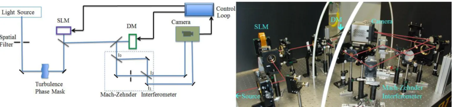
Our set-up can use different light sources either a He-Ne laser or a broadband white laser of around 500 to 900 nm spectral range. Each source will pass through a spatial filter at the focus of a lens, to build a clean wavefront collimated beam. A diaphragm at this position, represents the pupil of our setup which can be disturbed by a rotating phase screen. This aberrated pupil is reimaged several times in the setup through 2f optical systems. The first reimaged pupil is on the Spatial Light Modulator (SLM), the second on the Deformable Mirror (DM) and finally on the Camera imaging the two Mach-Zehnder outputs. All these elements can be seen on the following figure1.
Figure 1: Optical scheme of the XAO setup with the picture associated.
The pupils are optimized to each plane: on the SLM which is a 512x512 pixels liquid crystal, on the DM which is 12x12 actuators membrane, and on the Mach-Zehnder camera, the pupils are imaged with more than 1200 pixels in diameter. The table 1 below, compares the performances of our setup to the one expected for and XAO for 30m-class ELTs. One can assess the spatial resolution we need to achieve for the woofer or the tweeter corrector since ELTs XAO will require more than 20000 actuators13. The wavefront correction dynamic is
limited to one wavelength for our Spatial Light Modulator whereas the Deformable Mirror is able to cope with 4 to 5 deformation. This woofer-tweeter architecture aims at increasing the Strehl ratio up to 95% and dealing with large wavefront amplitudes. The control of all the elements is done via a Linux workstation, using Yorick language. One goal of our set-up is to test the different algorithms to implement to reach the high control frequency required.
System overview
XAO Setup scale ELT scale
Mach-Zehnder wavefront sensor
Pupil spatial resolution 1200 pixels 3.5cm Wavefront detection accuracy ~a few nanometer
Deformable Mirror corrector: woofer
Pupil spatial resolution 12x12 actuators 2.9m Wavefront correction dynamic ~6 microns PTV
Spatial Light Modulator corrector: tweeter
Pupil spatial resolution 512x512 pixels 7 cm Wavefront correction accuracy ~4 nanometer
Turbulence phase screen
Pupil spatial resolution 3000 pixels on diameter 1cm Wavefront accuracy ~15 nanometer
Control Loop
Control frequency ~100Hz ~1kHZ
Table 1: System overview and comparison with ELT scale requirements
3. DEFORMABLE MIRROR CALIBRATION
The woofer corrector is a Boston Micromachine continuous membrane deformable mirror (DM). This microelectromechanical system (MEMs) has 140 actuators on a 12x12 grid, for a 4.4×4.4 mm clear aperture. The inter-actuator spacing is 400 μm. This DM exhibits a maximum stroke of 3.5 microns. This element has been calibrated first using a ZYGO interferometer (see Figure 2) and in a second step directly on the Mach Zehnder. For both measurements we have used control maps based on the supplier flat map and offsetting 9 actuators over the surface. We consider that actuators separated by 3 actuators do not influence each other.
Figure 2: ZYGO deformation measurement (=632nm) of the DM membrane: a) mirror at rest ~1250nm deflection, b) manufacturer flatmap ~300nm deflection, c) and d)~1.5micron offset applied to 9 actuators.
From this set of measurements one could retrieve the influence function of each actuator and its calibration14. The figure 3 shows that the influence of one actuator does not go further than a 2 actuators distance, and that we can consider a linear region of deflection of 1 micron PTV.
Figure 3: DM calibration Left: Deformation radial profile for each of the 140 actuators, at various tension offsets
from the flatmap, ranging from -135V to +53V. Right: Maximum deflection for each of the 140 actuators as a function of the tension offsets
The DM can be calibrated on the Mach Zehnder directly. On the Figure 4 below, is shown the output of the Mach Zehnder camera using the He-Ne source. The two pupils of the symmetric and anti-symmetric port are imaged. Six actuators of the DM can be seen, offseted from the flatmap of one wavelength approximately. The error signal along one horizontal strip containing two actuators clearly shows two peaks with respect to the flatmap error signal, and also a slight shift of the flatmap interference pattern, due to the influence function of the actuators in a MEMS.
Figure 4: Left: Calibration image on the Mach Zehnder interferometer, 6 actuators have been set to -20V from
the flatmap, Right: Comparison of the horizontal cuts averaged error signal of the flatmap (in black) to the one with actuators activated (in red).
4. SPATIAL LIGHT MODULATOR CALIBRATION
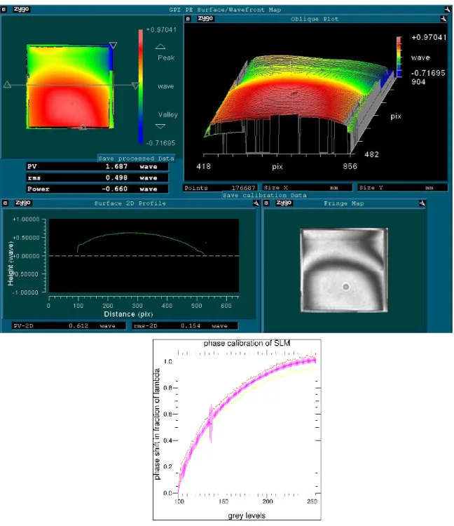
The tweeter corrector is a Meadowlark (formerly Boulder Nonlinear Systems i.e. BNS) liquid crystal spatial light modulator (SLM), 512×512 pixels on a 7.68 mm square grid. The XY nematic liquid crystal SLM is optimized to produce a full wave of phase stroke upon reflection at 632nm. It induces phase only modulation on a polarized input beam. As for the DM, the SLM has been first calibrated on the ZYGO interferometer (see Figure 5). The SLM is addressed with a linear ramp of modulation in one direction to cover the full 2 phase variation. Each pixel of SLM can be addressed with a grey level ranging from 0 to 255 in grey level. Below a threshold of 100 in grey level the SLM does not respond uniformly from one pixel to another. This calibration measurement has been done above this threshold.
Figure 5: Calibration of the SLM loaded with a phase ramp on the vertical direction, on the ZYGO
interferometer. Middle right: the interference pattern recorded on the ZYGO, Top pictures: 2D and 3D representation of the reconstructed phase, Middle left: Cut in the horizontal direction of the phase map. Bottom:
response of the pixels to the grey level ramp, average and standard deviation. One can see on all the pictures an artefact due to a dust in the ZYGO.
A further step in the calibration will be to build a pixel to pixel response of the SLM to improve the performance, and potentially use the SLM over the 2 phase correction if necessary. The SLM can also be calibrated directly on the Mach Zehnder. Here below on figure 6, one can clearly see the 2 phase shift induced by the SLM inside a square, on the Mach Zehnder pupils outputs.
Figure 6: Impact on the Mach Zehnder output images of the SLM loaded with a map
containing a squared shifted in phase by 2.
5. FIRST LOOP IMPLEMENTATION OF BOTH CORRECTORS
All active correctors being characterized, we have fed them with the Mach Zehnder error signal. On a first approximation as detailed in chapter 2 we have used the simple combination of the 2 outputs of the Mach Zehnder (I2–I1) / (I2+I1), to build our error signal. To do so, a spatial calibration of the 2 pupils recorded on the
camera has been implemented. A target is positioned on the input pupil, and an image with only one arm of the Mach Zehnder i.e. an image without interference is recorded. Each pupil is sampled with ~1200 pixels on its diameter. A matching program using the affine scale invariant matching method15 has been used. It matches key points from one pupil to the second one, it becomes then possible to retrieve the translation, rotation and magnification necessary to fit one pupil to the other. This method allows doing calculation on the pupils within the pixel accuracy, to properly compute the error signal.
Figure 7: Top part shows images not corrected whereas the bottom part are images after correction by the SLM,
signal (I2–I1) / (I2+I1) using the matched pupils, and on the right side is a cut of the error signal before and after
correction.
On Figure 7 one can see the phase correction achieved sending the error signal calibrated to the SLM size and phase. The phase residuals could be reduced improving the step of SLM size matching and using an inverse approach to compute the error signal.
The same simple correction has been implemented on the DM corrector and can be seen on Figure 8. Here also we can improve the correction signal using a more adapted influence function of the DM actuators and a better spatial matching.
Figure 8: Top part shows images not corrected whereas the bottom part are images after correction by the DM,
Left side are the raw pupils images at the output of the Mach Zehnder, on the middle are the computed error signal (I2–I1) / (I2+I1) using the matched pupils, and on the right side is a cut of the error signal before and after
correction.
These first results validate the use of a Mach-Zehnder to achieve very high strehl ratio (90% Strehl ratio has been obtained on our test bench).We foresee several improvements to make the measurements more accurate and to improve the robustness of this WFS in order to unable on sky use: We plan to implement and inverse approach to properly build the error signal to minimize residual errors. We plan to improve the spatial calibration for both SLM and DM. We can produce a pixel to pixel phase calibration for the SLM, and a better fitted influence function for the DM actuators. We also plan to upgrade our light source with a less coherent one like the broadband laser which will reduce the injection of high order fluctuations from interferences. Last but not least we plan to test the benefit of the fractal iterative method (FRiM)17, a fast iterative algorithm for minimum variance wavefront reconstruction and control.
6. CONCLUSION AND PERSPECTIVES
We have built an experimental WFS dedicated to ELTs to accurately estimate and correct the wavefront phase errors at small spatial scale, using a Mach Zehnder interferometer and a tweeter-woofer phase correctors architecture (DM and SLM) working in closed loop. The phase correctors were characterized using a Zygo interferometer, and directly on the Mach Zehnder interferometer. A simple method was used to build the error
signal. First results obtained with the MZWFS, with monochromatic light already show an improvement of the Strehl ratio up to 90%. But this can be improved with a better model of all elements from the error signal to the correctors calibration. The next steps are the use of adapted control algorithms like Frim among with the use of polychromatic light to reduce fringe effects.
ACKNOWLEDGEMENT
The authors are grateful to the LABEX Lyon Institute of Origins (ANR-10-LABX-0066) of the Université de Lyon for its financial support within the program "Investissements d'Avenir" (ANR-11-IDEX-0007) of the French government operated by the National Research Agency (ANR).
REFERENCES
[1] Hinkley, S., Oppenheimer, B. R., Zimmerman, N., et al., "A New High Contrast Imaging Program at Palomar Observatory," PASP 123, 74 (2011).
[2] Macintosh, B., Graham, J. R., Ingraham, P., et al., "The Gemini Planet Imager: First Light," PNAS 111, 12661-12666 (2014).
[3] Beuzit, J., Feldt, M., Dohlen, K., et al., "SPHERE: a planet finder instrument for the VLT," Proc. SPIE
7014, 701418-12 (2008).
[4] Fusco, T., Sauvage, J.-F., Petit, C., et al., "Final performance and lesson-learned of SAXO, the VLT-SPHERE eXtreme AO: from early design to on-sky results," Proc. SPIE 9148,91481U-15 (2014). [5] Guyon O., "Limits of Adaptive Optics for High-Contrast Imaging," ApJ 629, 592-614 (2005).
[6] Angel, J. R. P., "Ground-based imaging of extrasolar planets using adaptive optics," Nature 368, 203 (1994).
[7] Langlois, M., Angel, J. R. P., Lloyd-Hart, M., et al., "High Order, Reconstructor-Free Adaptive Optics for 6-8 meter class Telescopes," Proc. Beyond Conv. AO 58, 113-120 (2001).
[8] Dohlen, K., "Phase masks in astronomy: From the Mach-Zehnder interferometer to coronagraphs," EAS
Publications Series 12, 33–44 (2004).
[9] Zernike, F. "Diffraction Theory of the Knife-Edge Test and its Improved Form, the Phase-Contrast Method," MNRAS 94, 377 (1934).
[10] Bloemhof, E. E., & Wallace J. K., "Phase contrast techniques for wavefront sensing and calibration in adaptive optics," Proc. SPIE 5169, 309-320 (2003).
[11] Ragazzoni, R., "Pupil plane wave-front sensing with an oscillating prism," J. Mod. Opt. 43, 289–293 (1996).
[12] Langlois, M., Pasanau, C., Leroux, B., et al., "Progress with extreme adaptive optics test bench for ELT at LAM," Proc. SPIE 7015, 701544 (2008).
[13] Yaitskova N., Dolhen K., Dierickx P., Montoya L., "Mach-Zehnder interferometer for piston and tip-tilt sensing in segmented telescopes: theory and analytical treatment" J. Opt. Soc. Am. A 22, 1093–1105 (2005)
[14] Delacroix, C., Langlois, M., Loupias, M., et al., "Development of an ELT XAO testbed using a Mach-Zehnder wavefront sensor: calibration of the deformable mirror," Proc. SPIE 9617, 96170G-9 (2015). [15] G. Yu, J-M Morel, “ASIFT: An algorithm for Fully Affine Invariant Comparison”, Image Processing
On Line, 1 (2011) http://dx.doi.org/10.5201/ipol.2011.my-asift
[16] Lane, R. G., and Tallon, M., "Wave-front reconstruction using a Shack-Hartmann sensor," Appl. Opt.
31, 6902-6908 (1992).
[17] Tallon, M., Tallon-Bosc, I., Béchet, C., et al., "Fractal iterative method for fast atmospheric tomography on extremely large telescopes," Proc. SPIE 7736, 77360X (2010).