HAL Id: tel-01526678
https://pastel.archives-ouvertes.fr/tel-01526678
Submitted on 23 May 2017HAL is a multi-disciplinary open access archive for the deposit and dissemination of sci-entific research documents, whether they are pub-lished or not. The documents may come from teaching and research institutions in France or abroad, or from public or private research centers.
L’archive ouverte pluridisciplinaire HAL, est destinée au dépôt et à la diffusion de documents scientifiques de niveau recherche, publiés ou non, émanant des établissements d’enseignement et de recherche français ou étrangers, des laboratoires publics ou privés.
generation of Terawatt-class laser sources devoted to
attosecond physics
Hermance Jacqmin
To cite this version:
Hermance Jacqmin. Coherent combining of few-cycle pulses for the next generation of Terawatt-class laser sources devoted to attosecond physics. Optics [physics.optics]. Université Paris Saclay (COmUE), 2016. English. �NNT : 2016SACLX064�. �tel-01526678�
NNT : 2016SACLX064
T
HESE DE DOCTORAT
DE
L’U
NIVERSITE
P
ARIS
-S
ACLAY
PREPAREE A
“L’ECOLE
POLYTECHNIQUE”
E
COLED
OCTORALE N° 572
Ondes et matières
Spécialité de doctorat : Physique
Par
Mme Hermance Jacqmin
Coherent combining of few-cycle pulses for the next generation of
Terawatt-class laser sources devoted to attosecond physics
Thèse présentée et soutenue à l’ENSTA, le 07 octobre 2016 :
Composition du Jury :
M. F. Balembois, Professeur, IOGS, Président du Jury
M. C. Durfee, Professeur, Colorado School of Mines, Rapporteur M. E. Cormier, Professeur, CELIA, Rapporteur
M. M. Hanna, Chargé de recherche, IOGS, Examinateur Mme A. Jullien, Chercheuse, INLN, Encadrante M. Rodrigo Lopez-Martens, LOA, Directeur de thèse
Remerciements 2
Résumé 4
Abstract 7
General introduction 8
I Towards a relativistic laser source 11
1 Introduction 12
2 General view of a relativistic laser source 16
2.1 Main concepts of ultrashort pulses . . . 17
2.1.1 Description of an ultrashort pulse . . . 17
2.1.2 Temporal contrast . . . 18
2.2 Salle Noire 3.0 laser specifications . . . 18
2.3 Layout of the laser . . . 19
3 Front-end performance and characterization 21 3.1 Front-end description . . . 22
3.1.1 Oscillator . . . 22
3.1.2 CEP module . . . 23
3.1.3 First CPA - description . . . 25
3.2 CEP stabilization performances . . . 26
3.3 Spectro-temporal characterization . . . 27
3.3.1 Best performance in terms of coherent contrast . . . 27
3.3.2 Coherent contrast issues . . . 28
3.3.3 Degradation of the coherent contrast by nonlinear temporal diffraction . . . 29
3.3.4 Incoherent contrast measurement . . . 32
3.4 Spatio-temporal coupling . . . 32
3.5 Contrast enhancement of the front-end . . . 39
3.5.1 Setup description . . . 39
3.5.2 Preliminary experimental results . . . 40
3.5.3 Conclusion . . . 40
4 Technological challenges of the 2ndCPA 42 4.1 Stretcher-compressor design . . . 43
4.1.1 Technological choice for CEP stable operation . . . 43
4.1.2 Necessity to move from the scheme “Bulk stretcher - GRISM compressor” to “Öffner stretcher - TGC” . . . 44
4.1.3 Matlab calculations for devices setting . . . 45
4.1.5 First experimental tests with the Öffner-type stretcher . . . 52
4.1.6 Optical design of the TGC . . . 53
4.1.7 Conclusion . . . 54
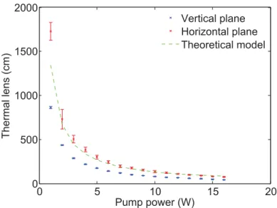
4.2 Thermal issues and diagnostics . . . 54
4.2.1 Analytical calculation of the heat rise in a pumped Ti:Sa crystal . . . 55
4.2.2 Thermal lens calculation from the heat rise map . . . 58
4.2.3 Thermal diagnostics . . . 60
4.3 Simulation of the amplification process in the power amplifier . . . 68
4.3.1 CommodPro Simulations . . . 68
4.3.2 Nonlinear temporal diffraction implies a compromise between contrast and energy stability . . . 70
4.4 Conclusion . . . 72
5 Towards Terawatt-class few-cycle pulses 73 5.1 Testing two metrology devices for ultra-short pulse measurement . . . 74
5.1.1 Wizzler-USP (Fastlite) . . . 74
5.1.2 D-scan (Sphere Photonics) . . . 74
5.1.3 Experimental results with sub-4 fs pulses . . . 74
5.2 The post-compression challenge . . . 77
II New post-compression techniques for intense pulses 78 6 Introduction 79 7 Exploring the high energy XPW setup 82 7.1 Theoretical background and state-of-the-art . . . 83
7.2 Numerical calculation with a 10 mJ, 25 fs Gaussian pulse . . . 84
7.3 Experimental implementation (10 mJ, 22 fs, 1 kHz) . . . 87
7.4 XPW generation with a hollow-fiber spatial filtering . . . 89
7.5 XPW generation with a glass-cone for spatial filtering . . . 93
7.6 Numerical results and comparison to the experimental ones . . . 97
7.7 Assessment of the two experimental runs . . . 98
8 Pulse dividing and combining in a hollow fiber compressor 100 8.1 Principle of pulse dividing and coherent combining . . . 102
8.2 Overview of the pulse dividing and combining implementations . . . 102
8.2.1 Pulse amplification . . . 102
8.2.2 Pulse synthesis in spectral domain . . . 103
8.2.3 Pulse nonlinear compression . . . 103
8.3 Implementing pulse division and combination in a hollow fiber post-compressor . . 104
8.3.1 Spatial pulse division . . . 104
8.3.2 Temporal pulse division . . . 105
8.4 Birefringent plate choice . . . 106
8.4.1 Material . . . 106
8.4.2 Crystallographic orientation . . . 106
8.4.3 Thickness . . . 107
8.5 Plates theoretical and experimental characterizations . . . 108
8.5.1 Identification of the plates crystallographic axes . . . 108
8.5.2 Spectrometer requirement . . . 109
8.5.3 Commercial specifications of the used calcite plates . . . 109
8.5.4 Theoretical calculation of the group delay introduced by the plates . . . 109
8.5.5 Group delay versus θi- Comparison between experimental data and theoret-ical values . . . 112
8.5.6 Delay chromatism . . . 114
8.6 Experimental implementation . . . 116
8.7 Numerical simulation tool . . . 119
8.8 Experimental results with two replicas in the optimal conditions . . . 119
8.9 Measurement of the residual relative phase . . . 125
8.10 Optimizing the process efficiency and the temporal fidelity of the combined pulse . 129 8.10.1 Polarization changes due to the mirrors before the fiber . . . 129
8.10.2 Differential GDD in the Combining Setup . . . 132
8.10.3 Ionization . . . 135
8.10.4 Cross-phase modulation (XPM) between the replicas . . . 136
8.10.5 Nonlinear interactions between the replicas pedestals . . . 138
8.11 Extending the experiment to 4 replicas . . . 150
8.11.1 Plates tuning and polarization of the combined pulse in an ideal configuration 150 8.11.2 Plates tuning when nonlinear interactions occur between the replicas . . . . 153
8.11.3 Differential GDD issues . . . 155
8.11.4 Experimental results with 4 replicas . . . 157
8.12 Conclusion . . . 158
9 N+ 2 air lasing experiments with combined pulses 159 9.1 Introduction . . . 159
9.2 Experimental setup . . . 160
9.3 Experimental results . . . 161
9.3.1 Air lasing when optimizing the combining efficiency . . . 161
9.3.2 Air lasing when optimizing the combined pulse duration . . . 162
9.3.3 Chirp scan coupled with Wizzler measurements . . . 164
9.3.4 CEP dependance of the air lasing signal: preliminary results . . . 165
9.4 Conclusion . . . 167
General conclusion 168
A Dispersion influence on a Gaussian pulse 170
B Layout of the FemtoPower 174
C Experimental analysis of the main CEP noise sources in Salle Noire 2.0 175
D Laser implementation in Salle Azzurra 178
Ces trois années de thèse ont été l’occasion de rencontrer de nombreuses personnes et je souhaite remercier tous ceux qui ont contribué à ce travail.
Je tiens tout d’abord à remercier Rodrigo Lopez Martens et Christophe Simon Boisson, qui ont mis en place le financement de cette thèse, et qui m’ont confié leur projet de développement d’une source laser. Cette thèse a été réalisée dans le cadre d’un contrat CIFRE avec Thales Optronique et a donc été l’occasion de rencontrer Olivier Chalus, que je remercie pour les échanges que nous avons eu, ainsi que Paul Jougla, que je remercie pour sa disponibilité et son aide précieuse alors que j’effectuais mes premières simulations en Zemax en début de thèse.
Je tiens ensuite à remercier Eric Cormier, Charles Durfee, Marc Hanna et François Balembois, qui ont accepté de faire partie de mon jury de thèse, et qui ont pris le temps d’évaluer mon travail. Ma thèse s’est déroulée au sein du groupe PCO (Physique du Cycle Optique) au Laboratoire d’Optique Appliquée. Un grand merci aux autres thésards de ma génération, Maïmouna Bocoum, Frédérik Boehle, Maxence Thévenet et Benoît Beaurepaire, toujours disponibles pour débattre de sujets divers et variés. Je tiens également à remercier Jean-Philippe Rousseau, qui m’a familiarisé avec les sources lasers femtosecondes en début de thèse, ainsi qu’Olivier Albert, qui était toujours d’excellent conseil. Enfin, je souhaite remercier Magali Lozano, avec qui j’ai eu la chance de tra-vailler lors de ma dernière année de manips, et qui reprend le flambeau de la chaîne laser 3.0.
Au cours de mes deux premières années de thèse, j’ai eu la chance de travailler avec une laseriste hors pair : Aurélie Jullien. Le poids d’un simple ’merci’ semble bien trop léger en com-paraison de tout ce que tu m’a transmis. Si j’ai pris goût à la femto, c’est bel et bien grâce à toi. J’ai également eu la chance de travailler avec Brigitte Mercier, qui m’a formée sur le logiciel Miro et appris à porter un regard critique, aussi bien sur les résultats expérimentaux que numériques. Grâce à vous, les expériences de combinaison cohérente d’impulsions ultracourtes furent une belle aventure ! Je n’oublierai pas votre soutien sans failles lors de la période de rédaction et de préparation de la soutenance, malgré nos situations géographiques et professionnelles respec-tives changeantes.
Le groupe PCO travaillant en étroite collaboration avec le groupe APPLI, j’ai interagi quotidien-nement ou presque avec Jérôme Faure, Geoffrey Galle, Diégo Guénot, Dominykas Gustas, Davide Boschetto et Aline Vernier. Je tiens à les remercier pour tous les échanges enrichissants que j’ai pu avoir avec les uns et les autres. Je tiens également à remercier Florian Mollica, pour m’avoir dévoilé les subtilités du SID4, mais avant tout pour son soutien indéfectible et ses bons plans de soirées.
J’ai eu la chance de pouvoir effectuer des expériences de filamentation dans l’air avec le groupe ILM. Un grand merci à Yi Liu et Andre Mysyrowicz, pour avoir pris le temps de me faire découvrir une physique riche et pleine de mystères, ainsi qu’à Pengji Ding, pour sa patience alors que la stabilisation de la CEP me donnait du fil à retordre. Je tiens également à remercier Yves-Bernard André, qui est venu à la rescousse en salle Azzurra un certain nombre de fois, que ce soit pour
des problèmes de mise à la terre ou de chillers. Merci à Guillaume Point et Alessandro Flacco, qui m’ont initié aux techniques de dépliements de phase 2D. Enfin, je tiens à remercier Amélie Jarnac, pour m’avoir fait renouer avec mon passé de cavalière.
Je tiens à remercier tout particulièrement l’équipe du secrétariat : Patricia Toullier, Sandrine Tricaud, Octavie Verdun, Lucie Huguet et Carole Gratpanche. Ayant commencé ma thèse dans une salle vide, j’ai dû passer un nombre conséquent de commandes et j’ai toujours pu compter sur leur efficacité et leur soutien. Un grand merci également au service mécanique : Jean-Lou Charles, Mickaël Martinez et Bernard Allali, ainsi qu’aux membres de SourceLab : François Sylla, Guillaume Bouchon, Cédric Sire et Aurélien Ricci. Enfin, je n’oublie pas de remercier Jean-Philippe Goddet pour son écoute dans les moments délicats.
Au cours de ces trois années, j’ai eu l’opportunité de collaborer avec des groupes de recherche extérieurs au LOA. Je tiens à remercier Frédéric Druon, Marc Hanna, Dimitrios Papadopoulos et Florent Guichard, membres du groupe lasers du Laboratoire Charles Fabry, pour leur contribution aux expériences de combinaison cohérente. Je tiens également à remercier Gustave Pariente, avec qui j’ai construit et testé un diagnostique TERMITES, ainsi que Fabien Quéré, pour les discussions intéressantes sur les résultats obtenus. Un grand merci à Antoine Dubrouil, qui est venu tester ses prototypes en salle Azzurra, et à qui je souhaite plein de réussite dans son projet d’entrepreunariat. Enfin, j’ai eu la chance de bénéficier de nombreux soutiens extérieurs, en particulier ma famille et mes amis. Je ne remercierai jamais assez mes parents, qui m’ont toujours soutenue dans tous les projets que j’ai entrepris. Je tiens à remercier Thibaut, pour m’avoir transmis son goût pour les sciences, ainsi que Camille, pour son aide précieuse dans les moments difficiles. Merci à Olivier, Christian, Mathilde et Cécile, d’avoir eu la curiosité de venir à ma soutenance, sachant pourtant d’emblée que mes propos ne leur seraient pas familiers. Un très grand merci à Gabriel, Erwan et Nicolas, qui sont toujours au rendez-vous dans les moments importants, et qui ont bravé le plateau de Saclay pour venir à ma soutenance. Merci à Marie-Christine et Vincent, dont le sens de l’accueil et la simplicité demeureront toujours un exemple pour moi. Un grand merci à Laurène, pour tous les bons moments passés ensemble. Un grand merci également à Rémi, pour tout ce que nous avons partagé, et qui a pris le risque de passer la nuit enfermé sur un parking en pleine campagne pour capter au mieux la 4G, et me faire répéter ma soutenance, avant de se lancer dans un débat 5h durant, comme à notre bonne habitude. Je ne remercierai jamais assez Elsa, avec qui je partage une amitié depuis quinze ans maintenant, et qui m’a tant apporté tout au long de ces années. Enfin, mes pensées se tournent vers mon compagnon de route, Jordan, avec qui j’ai partagé et construit tant de choses ces dernières années.
Ce travail de thèse s’inscrit dans le cadre du développement d’une source laser TW, de cadence élevée, stabilisée en phase, et délivrant des impulsions de quelques cycles optiques pour explorer la physique attoseconde. Ce type de source laser permet d’étudier la physique des plasmas à haute intensité, et plus particulièrement la génération d’ondes attosecondes par miroir plasma dont le principe peut être simplifié de la manière suivante : la focalisation d’une source primaire délivrant des impulsions IR femtosecondes sur une cible en verre entraîne la création d’un plasma. Dans le cas où les impulsions délivrées par la source primaire sont suffisamment intenses, le plasma se comporte comme un miroir et réfléchit le champ incident avec une forte distorsion : le champ réfléchi est alors constitué d’ondes attosecondes dont les composantes spectrales sont dans la gamme XUV. Ce type d’expérience est fortement lié aux caractéristiques de la source primaire IR, telles que l’intensité ou la phase des impulsions.
Une manière d’augmenter l’intensité crête des impulsions sur cible consiste à réduire autant que possible la durée des impulsions. Il est aujourd’hui possible de générer des impulsions de 5 fs à mi-hauteur et dont le spectre est centré à 800 nm. De telles impulsions contiennent seulement 4 oscillations du champ électrique ou cycles optiques, la période d’oscillation du champ électrique correspondant étant de 2,67 fs. On peut donc parler de régime du cycle optique. Dans le cadre de la génération d’ondes attosecondes par miroir plasma, le cahier des charges de la source laser peut être résumé comme suit :
• La durée des impulsions doit être de 5 fs pour atteindre un niveau d’intensité crête suff-isamment élevé sur cible et explorer un régime d’interaction lumière-matière qualifié de relativiste. Dans un tel régime, la vitesse des électrons atteint la vitesse de la lumière. • Le contraste des impulsions doit être suffisant pour éviter tout phénomène de pré-ionisation
de la cible.
• La phase entre le champ électrique et son enveloppe (Carrier Envelope Phase, CEP) doit être stabilisée tir à tir pour contrôler l’interaction laser-matière sur une échelle sub-femtoseconde. • Un taux de répétition élevé est souhaitable pour mesurer le rayonnement XUV avec un
rap-port signal sur bruit élevé.
La contrainte en terme de contraste implique une architecture laser à deux étages d’amplification à dérive de fréquence (Chirped Pulse Amplification, CPA), séparés par un étage de filtrage tem-porel. D’autre part, la stabilisation de la phase des impulsions contraint les schémas d’étirement et de compression. Une source laser avec ce type d’architecture a déjà été réalisée dans le cadre du projet de la Salle Noire 2.0 (Jullien et al, Opt. Lett., 2014). Mon travail de thèse a consisté à dévelop-per la Salle Noire 3.0, source laser délivrant deux fois plus d’énergie que la source précédente (Salle Noire 2.0). L’architecture retenue pour cette nouvelle source laser est la suivante : un oscillateur injecte un premier CPA qui délivre des impulsions de 30 fs avec une énergie de 1,6 mJ. Un étage de filtrage temporel permet alors d’augmenter le contraste des impulsions de plusieurs ordres de grandeur. La transmission de ce filtre étant de l’ordre de 20 %, un second CPA est nécessaire pour atteindre un niveau d’énergie de l’ordre de 25 mJ. A ce stade de la chaîne laser, les impulsions ont une durée de 25 fs. Pour réduire la durée des impulsions et atteindre le régime du cycle optique,
l’ajout d’un étage de post-compression est nécessaire. Il est prévu ainsi de générer des impulsions de 5 fs avec une énergie de 15 mJ.
La première partie de ce manuscrit est consacrée d’une part à la caractérisation expérimentale des premiers modules de cette chaine laser, et d’autre part aux études et simulations nécessaires à la définition et au dimensionnement des modules suivants. La caractérisation du front-end (os-cillateur et premier CPA) ainsi que de l’étage de filtrage temporel est détaillée au début de cette partie. Les performances en terme de durée, contraste et stabilisation de la CEP y sont présen-tées. La problématique de dégradation du contraste cohérent par effet de diffraction temporel non linéaire est abordée. Enfin, l’exploitation et la mise en place d’un diagnostique permettant de quantifier les couplages spatio-temporels de la source laser sont détaillés. Les différents choix technologiques et simulations de la suite de la chaine sont abordés en fin de partie. En particulier, le design de l’étireur et du compresseur du second CPA est discuté, les problèmes liés aux effets thermique dans les étages d’amplification sont mis en évidence au travers de simulations dont les résultats sont confrontés à des mesures expérimentales, et les résultats de simulation du proces-sus d’amplification au sein du second CPA sont présentés.
La deuxième partie de ce manuscrit est consacrée à la post-compression d’impulsions in-tenses. La réalisation de l’étage de post-compression constitue en effet une réelle difficulté en rai-son du niveau d’intensité crête des impulsions disponibles à la sortie du second CPA. Deux tech-niques sont proposées. La première technique consiste à exploiter un effet non linéaire d’ordre trois, la génération de polarisation croisée (Crossed Polarized Wave (XPW) generation), dans des cristaux de BaF2. Le dimensionnement et la mise en oeuvre d’un tel dispositif ont été réalisés dans le cadre de la Salle Noire 2.0. Les résultats de cette campagne d’expérience ont été confron-tés à ceux de simulations numériques. Les limites de cette technique, en partie liées au niveau d’intensité élevé des impulsions incidentes et aux caractéristiques de la source laser disponible, sont mises en évidence.
Une autre technique de post-compression efficace pour obtenir des impulsions de quelques cy-cles optiques consiste à élargir le spectre des impulsions laser par automodulation de phase dans une fibre creuse remplie de gaz, puis à compenser la phase spectrale introduite avec des miroirs chirpés. Cette technique convient à des impulsions dont l’énergie est inférieure au millijoule. Au-delà, la transmission et la stabilité du compresseur chutent fortement à cause d’effets non linéaires tels que l’autofocalisation et l’ionisation. Pour comprimer des impulsions énergétiques et dont la phase de l’enveloppe est stabilisée par rapport à la porteuse (stabilisation de la CEP), il est possible de diviser l’impulsion initiale en plusieurs répliques d’énergie moindre et de ré-duire ainsi l’intensité crête en entrée de fibre. Le spectre de chaque réplique est alors élargi in-dépendamment. Dans le cadre de cette thèse, la combinaison cohérente passive d’impulsions de quelques cycles optiques issues d’une fibre creuse remplie de gaz est démontrée pour la pre-mière fois. L’utilisation de lames biréfringentes (calcite) dont l’orientation est soigneusement déterminée permet de générer et combiner des répliques avec une efficacité élevée. Ainsi, dans le cas d’une division en deux répliques, des impulsions stabilisées en phase (CEP), de durée 6 fs et d’énergie 0.6 mJ ont été générées de manière fiable et reproductible. L’étude détaillée de cette technique, aussi bien théorique qu’expérimentale, a permis de mettre en évidence les conditions requises pour générer des impulsions de quelques cycles optiques et présentant un bon contraste temporel. Plus précisément, la phase spectrale relative entre les répliques peut être mesurée à l’aide d’une méthode interférométrique permettant de quantifier les déphasages résiduels dus à la lame qui recombine les répliques, ainsi que ceux induits lors de la propagation dans la fibre par d’éventuels effets de modulation de phase croisée ou d’ionisation. Les effets qui affectent le processus de combinaison des répliques, tels que les modifications des états de polarisation des répliques ou bien les interactions non linéaires entre les répliques, sont analysés en détail. Une méthode est proposée pour minimiser ces effets, même dans le cas plus critique de la division et
The framework of this thesis is the design and development of a TW-class, high-repetition rate, CEP-stabilized, few-cycle laser system devoted to attosecond physics. Few-cycle pulses includes only a few oscillations of the carrier wave (duration about 5 fs for 800nm central wavelength) and are not directly available at the output of typical femtosecond sources. One of the most popular techniques used for producing such pulses with high spatial quality is nonlinear spectral broad-ening in a gas-filled hollow-core fiber followed by temporal compression with chirped mirrors. However, as the input pulse energy approaches the milliJoule level, both the transmission and sta-bility of hollow fiber compressors rapidly drop with the onset of self-focusing and ionization. A way of overcoming this limitation is to divide the input pulse into several lower energy replicas that can be subsequently recombined after independent spectral broadening in the fiber. In this thesis, the passive coherent combining of millijoule energy laser pulses down to few-cycle dura-tion in a gas-filled hollow fiber is demonstrated for the first time. High combining efficiency is achieved by using carefully oriented calcite plates for temporal pulse division and recombination. Carrier-envelope phase (CEP)- stable, 6-fs, 800-nm pulses with more than 0.6 mJ energy were rou-tinely generated in the case of twofold division and recombination. A detailed theoretical and experimental analysis of this temporal multiplexing technique is proposed to explain the condi-tions required for producing few-cycle pulses with high fidelity. In particular, an interferomet-ric method for measuring the relative spectral phase between two replicas is demonstrated. This gives a measure of the phase mismatch in the combining plate, as well as that induced by eventual cross-phase modulation or ionization during propagation in the fiber. The effects degrading the combining process, as polarization change or nonlinear interactions between pulse replicas are analyzed in details. A method is proposed to overcome these limitations, even in the critical case of fourfold pulse division and combination.
Recent developments in ultrafast laser technologies over the two last decades enabled the gener-ation of extremely short laser pulses. Durgener-ations of a few femtoseconds can be now achieved (1 fs = 10−15s), with a few optical cycles of the electric field in the visible spectral range. Strongly focusing
such pulses allows to spatially and temporally concentrate the laser energy and to reach very high peak intensities, defined by I = E / (πr2τ) where E is the pulse energy, τ the pulse duration and r the radius of the focal spot.
Femtosecond lasers makes femtochemistry possible
The time feature for atoms motion is on the femtosecond scale. Pulses with similar durations make the vibration states of molecules measurable: femtosecond lasers offer the possibility to study ev-ery step of chemical reactions and to discover substances formed along the way from the original chemical product to the final one. A new research field has opened and leads to fruitful discov-eries: the Nobel Prize in Chemistry was attributed to Ahmed H. Zewail in 1999 for his studies of the transitions states of chemical reactions using femtosecond spectroscopy. To take our under-standing of matter further with the study of electron dynamics, femtosecond pulses are not short enough as the relaxation timescale of the electronic process is the attosecond (1 as = 10−18s).
Laser-matter interaction for attosecond pulse generation
Attosecond durations can be achieved in the XUV spectral range thanks to the High Harmonic Generation (HHG) process occurring via laser-atoms interactions. When a highly intense laser pulse is focused in a gas target (see Fig. 1), its electric field induces potential barrier curvature of atoms and leads to tunnel ionization of electronic wavepackets. Electrons bunches are accelerated by the laser electric field and acquire significant kinetic energies. The process is brief (a fraction one cycle of the electric field) and repeated every half-cycle of the driving pulse. Some electrons can recombine and convert their kinetic energy into coherent XUV photons. In the early 2000s, such a technique led to the generation of attosecond pulse trains [1, 2] and opened a new attrac-tive research domain [3, 4]. Attosecond pulses can indeed bring answers to the time removal of an electron from an atom or a molecule, the molecular orbitals rearrangement after an electron leaving, the electrons movement during chemical reactions, etc.
The femtosecond laser source intensity and the target properties determine the physical pro-cess involved in the laser-matter interaction. The HHG propro-cess does not occur in atomic gas tar-gets for laser intensities higher than 1014W.cm−2, when the ionization rate inside the gas is too
sig-nificant. Besides, the process efficiency is very low (10−6-10−5). As an alternative, plasma mirrors
are very promising because they allow HHG with laser intensities largely higher than 1014W.cm−2.
Their reflective surface is made of a dense plasma generated by an intense laser field via an ion-ization process of a solid target. This technology will permit to study ultra-intensity physics and to explore the relativistic regime achieved for laser intensities higher than 1018W.cm−2. In this
regime, the electric field makes a blanket of electrons on the mirror surface which oscillates at the laser frequency, with speeds close to the speed of light. This relativistic movement of the mir-ror surface induces HHG via Doppler effect. The reflected beam is made of not only the incident laser frequency but also of high order harmonics of the laser frequency. The highest harmonic
Extreme UV attosecond beam
IR few-cycle CEP-stable pulses
Off-axis parabola Rotating glass target Plasma mirror at focus
Figure 1 – Experimental setup for attosecond pulses generation (adapted from [5]). The IR beam is focused at a 1 kHz repetition rate onto a rotating glass target. The plasma created at the target surface emits a co-herent XUV radiation.
order that could be achieved is unknown but there is hope for generation of X rays. This regime is named relativistic because the electrons speed is about the light one, meaning that the mass variation of electrons must be taken into account, and that the magnetic force [-e v∧B] cannot be neglected. To date, the laws of linear and nonlinear optics are unknown in this regime. For all these reasons, plasma mirrors are considered as the second generation of attosecond sources [6]. They are able to provide attosecond sources with more intensity, lower pulse duration and shorter wavelengths than gas targets for instance. This considerably broadens the range of applications of attosecond sources, in addition to enabling the study of the behavior of matter under extreme light intensities. This last basic research project requires the development of laser sources deliv-ering pulses with enough intensity to reach the relativistic regime. Such laser systems are usually called relativistic laser sources.
Relativistic laser source specifications
The relativistic laser source specifications are very constraining. As explained previously, the pulse energy (resp. duration) must be high (resp. low) enough to reach relativistic intensities on target, always maintaining a good spatial and temporal pulse quality. Compromises must be done and there are two options. The pulse energy can be increased, but this implies a reduced laser repeti-tion rate [7]. It is also possible to decrease the pulse durarepeti-tion down to a few optical cycles, reduce the spot size on target and increase the laser repetition rate. In this case, the pulse energy is lim-ited. The PCO group chose this last option.
Attosecond pulse generation via plasma mirrors requires laser pulses with a high temporal contrast. Titanium Sapphire laser systems generate pulses which are surrounded by a pedestal of incoherent light on a nanosecond timescale (with a typical relative intensity between 10−6and
10−9) and by coherent parasitic pulses on a picosecond timescale (with a typical relative intensity
between 10−3 and 10−4). The incoherent temporal pedestal can be a limitation when focusing
intense laser pulses on a solid target. If its intensity is high enough to pre-ionize the target before the main pulse arrival, the plasma mirror cannot be created. The plasma induced by the laser pedestal spreads out before the interaction of the main pulse with the target. In the end, the main laser pulse interacts with a low density plasma, which is not of interest.
Working with few-cycle laser pulses necessitates that the phase between the electric field and its envelope, called Carrier Envelope Phase (CEP), be stabilized. The intensity of a pulse made of only two optical cycles is indeed strongly affected by a CEP shift. The variations of the CEP are in-fluenced by environment fluctuations (temperature, mechanical and acoustic vibrations, etc) and undesirable nonlinear effects experienced by pulses all along the laser chain. As a consequence, the CEP must be stabilized as close as possible to the target.
Finally, a repetition rate of 1 kHz is desirable to achieve significant XUV photon flux and to perform statistics. As a consequence, the thermal effects must be controlled in the amplification
stages, as well as in the compressor. A constant refreshment of the target consistent with the laser repetition rate is also required.
Motivation and outlines of the thesis
This thesis falls within the development of unique few-cycle laser sources by the PCO group. The first Salle Noire laser demonstrated for the first time HHG from solid targets at 1 kHz repetition rate in the few-cycle regime [8, 5]. The role of the CEP was specially highlighted.
An upgrade of this laser (Salle Noire 2.0) was aimed at increasing the available energy to 10 mJ, while implementing contrast enhancement in a double-CPA, CEP-stabilized system [9]. Some of the first associated results demonstrated the anti-correlated emission of HHG and electrons [10] and the role of the laser wavefront in the emission of fast electrons [11]. The reliable few-cycle pulse production from this laser source is still under process.
Based on these developments, the project presented here is devoted to further increase the energy on target. In this framework, this thesis aimed to conceive and develop a new high con-trast few-cycle CEP-stabilized Terawatt-class 1 kHz laser, which will be dedicated to attosecond pulses generation in the relativistic regime on solid target. This project draws its dynamism from the ELI project in Hungary, called ELI-ALPS (Extreme Light Infrastructure - Attosecond Light Pulse Source). Financial support was provided by Conseil Régional d’Ile-de-France and Thales Optron-ique.
The thesis manuscript is divided into two parts. The first part is dedicated to the dimensioning calculations I performed to design the entire laser chain. This involves optical design simulations of the key optical systems of the laser chain (stretcher and compressor), the amplification calcu-lations and a preliminary study on thermal issues. Some critical technological choices were made at the light of these calculations and the discussions with some suppliers. The experimental char-acterization of the front-end is also presented through temporal measurement, CEP stabilization and spatio-temporal coupling estimation.
The second part deals with the post-compression experiments performed in the framework of a research project founded by ELI-ALPS. This project was dedicated to the study of several options to post-compress multi-mJ pulses down to the few-cycle regime (< 10 fs). In this thesis, two differ-ent options were explored. I first presdiffer-ent a post-compression technique based on Cross-polarized wave generation (XPW) which was tested with a 10 mJ, 25 fs, 1 kHz laser source (Salle Noire 2.0). Another technique consisting in implementing a pulse dividing and combining setup in a hollow-core fiber post-compressor is then introduced and analyzed in details. This last setup was used to perform filamentation experiments with the ILM group, as shown in the last chapter.
Towards a high contrast few-cycle
CEP-stabilized Terawatt-class laser at
Introduction
The first femtosecond technology appeared in the 1970s with passively mode-locked dye lasers, delivering sub-1 ps pulses [12]. The dye laser principle is based on the use of organic molecules which are diluted in a solvent. The specificity of these molecules is their manifold energy levels. Their continuous emission in the spectral visible range allows the generation of short pulses via the use of mode-locking methods. In this way, a colliding-pulse mode-locking technique allowed the 100-fs barrier to be broken in the 1980s [13]. A few years later, 27 fs pulses were obtained thanks to a precise intracavity group-delay dispersion (GDD) management [14]. The shortest pulse du-ration obtained with a dye laser was 6 fs for energies about the nanojoule [15]. In this case, an extracavity pulse compression technique was used. The peak power upgrade of dye lasers could be then achieved thanks to kHz pump lasers. This is how tens of megawatts could be generated [16]. However, these laser sources require a constant dye circulation to avoid molecules breaking by the pumping process. This complicated implementation, in addition to the increasing demand for energies higher than the microjoule level, made this technology progressively outdated.
At the end of the 1980s, titanium-doped sapphire (Ti:Sa) crystals were identified as excellent candidates for broadband solid-state lasers [17]. The main reasons are listed below:
• These crystals can support a high thermal charge thanks to the excellent thermal conduc-tivity of sapphire.
• The very large gain bandwidth of Ti3+ions (≈ 650-1100 nm) is suited to ultrashort pulses generation.
• Ti:Sa exhibits a high saturation fluence so that significant energy can be extracted.
• High peak power can be achieved with this material, as it can be grown as large size crystals. The boundaries of Ti:Sa crystal-growth technology were pushed by the increasing demand for high peak power lasers, especially Petawatt lasers. As an example, the company Crystal Systems is now able to produce 170 mm diameter crystal boules with excellent properties. Further develop-ments are needed to meet the demand of the ELI platforms, consisting in 250 mm boules. In the end, Ti:Sa crystals are still at the front of the femtosecond lasers research area, although it became a proven technology a long time ago.
The successful career of Ti:Sa started in 1991, at the time of the first demonstration of a Kerr-lens mode-locked Ti:Sa laser oscillator [18], delivering 45 fs pulses thanks to extra-cavity disper-sion compensation with bulk. The advantage of these oscillators is their very fast response and the absence of saturable absorber medium. Further experimental work lead to a better understand-ing of the Kerr-lens mode-lockunderstand-ing process [19], showunderstand-ing that high spatial modes are not required to start and sustain mode-locking which is entirely due to self-focusing effect in the Ti:Sa rod.
In the first Kerr-lens mode-locked oscillators, pulse compression was managed with a pair of prisms. However, this compression device induces uncompensated high order dispersion. This is not the case of chirped multilayer mirrors, which introduce a constant negative dispersion over a
large frequency range. Such coatings were proposed by [20, 21] and exhibit negative dispersion on a 80 THz spectral bandwidth. Thanks to these innovative coatings, few-cycle pulses were routinely produced at the nanoJoule level, as demonstrated in [22]. Femtosecond Kerr-lens mode-locked Ti:Sa lasers became then a worldwide reference technology.
The amplification of pulses beyond the nanoJoule level is limited by the onset of self-focusing. The chirped-pulse amplification technique (CPA) proposed by [23] overcomes this limitation. Its principle relies on pulse temporal stretching before performing pulse amplification. The pulse peak power is thus strongly decreased in the amplifiers, avoiding the deleterious effects of self-focusing. At the end, high peak power is recovered via temporal compression. This is how pi-cosecond pulses were amplified from the NanoJoule to the Joule level [24]. Otherwise, 350 µJ, 55 fs compressed pulses were produced by implementing this technique with regenerative amplifiers operating at 1 kHz repetition rate [25].
The next purpose is dedicated to the progress of kHz laser systems. A recent paper overviews laser technologies with a similar repetition rate [26]. A survey of this state of the art with some additional references is summarized in Tab. 1.1. The best performance achieved with a dye laser, as well as performances of Ti:Sa rod kHz lasers, are gathered on Fig. 1.1. The Salle Noire 3.0 project follows on from the Salle Noire 2.0 one (10 mJ, 22 fs, 1 kHz) [9] and plans to deliver 25 mJ, 20 fs, pulses at 1 kHz repetition rate. These specifications correspond to a slight increase of both peak power and mean average power compared to the sources previously developed and based on the same technology (see Fig. 1.1). There are also additional constraints related to the contrast and CEP stability.
10
−110
010
110
210
−310
−210
−110
010
1Average power (W)
Peak power (TW)
Dye laser kHz Ti:Sa lasers Salle Noire 3.0Figure 1.1 – Summary of the key results in terms of average and peak power, obtained with dye lasers and Ti:Sa lasers these last decades.
The minimum pulse duration that can be obtained with a Ti:Sa-based laser system is about 20 fs. This is due to the limited spectral bandwidth of the gain in Ti:Sa crystals. To achieve the few-cycle regime, the femtosecond laser source must be completed by a post-compression stage. Nowadays, the most widespread method to spectrally broaden and temporally compress ampli-fied femtosecond laser pulses down to few-cycle duration is via self-phase modulation (SPM) in noble gas-filled hollow-fibers followed by chirped mirror compression. This technique was successfully implemented for the first time in 1996 [39]. A detailed overview of the main post-compression techniques is presented in Part 2.
To end this introduction, I should mention an another emerging technology suited to attosec-ond generation based on the OPCPA concept (Optical Parametric Chirped-pulse Amplification)
Ref. Year f E τ Ppeak Pmean Remark
[27] 1997 1 kHz 4 mJ 20 fs 0.2 TW 4 W Thermal lens managed through Ti:Sa crystal cooling to 125 K. [28] 1998 1 kHz 14 mJ 21 fs 0.66 TW 14 W Pulse compression managed
through a pair of prisms inserted in the regenerative amplifier.
[29] 2000 1 kHz 1.8 mJ 20 fs 0.09 TW 1.8 W Single multipass amplifier stage. Chirped mirrors provide compen-sation for gain narrowing and high-order dispersion.
[30] 2000 1 kHz 20 mJ 20 fs 1 TW 20 W A thermal lens imaging technique is preferred to Ti:Sa cryogenic cooling. [31] 2001 1 kHz 4 mJ 45 fs 0.09 TW 4 W
[32] 2001 7 kHz 1.3 mJ 24 fs 0.05 TW 9.1 W Single-stage laser amplifier. Ti:Sa crystal cryogenically cooled (77 K). [33] 2004 10 kHz 1.1 mJ 28 fs TW 11 W Single-stage amplifier with
cryo-genic cooling (73 K). The seed is negatively chirped so that compres-sion is achieved through bulk. [34] 2006 10 kHz 2.6 mJ 58 fs 0.045 TW 26 W
[35] 2009 1 kHz 6 mJ 30 fs 0.2 TW 6 W CEP noise = 90 mrad. [36] 2010 1 kHz 12 mJ 27 fs 0.44 TW 12 W
[37] 2011 1 kHz 13 mJ 40 fs 0.33 TW 13 W Cryo-cooling, CEP noise = 440 mrad.
[38] 2013 10 kHz 2 mJ 30 fs 0.067 TW 20 W Cryo-cooling, CEP noise = 320 mrad.
[9] 2014 1 kHz 8 mJ 22 fs 0.36 TW 8 W High contrast, CEP noise = 240 mrad.
Table 1.1 – State of the art of Ti:Sa rod lasers operating at kHz repetition rates and exhibiting 20-30 fs pulse durations. The last reference (2014) corresponds to the Salle Noire 2.0 performances.
[26]. In this case, the CPA technique is implemented together with optical parametric amplifiers. This technology is very attractive because there are no thermal issues unlike the Ti:Sa-based am-plifiers. Besides, the contrast requirement is easily achieved as the parametric gain occurs only within the duration of the pump pulse. The main disadvantages of OPCPA systems are: the limited aperture of the available nonlinear crystals, the synchronization issues between the pump and the signal, as well as the phase-matching issues. In general, many disadvantages of the Ti:Sa-based
General view of a relativistic laser source
Contents2.1 Main concepts of ultrashort pulses . . . 17
2.1.1 Description of an ultrashort pulse . . . 17
2.1.2 Temporal contrast . . . 18
2.2 Salle Noire 3.0 laser specifications . . . 18
In this chapter, I present the general concepts used to define and design the relativistic laser source. In a first step, I introduce the main characteristics of femtosecond laser pulses, restricted to the definitions extensively used in the manuscript. Next, I will present how the required laser specifications determine its architecture and the technical challenges that need to be overtaken.
2.1 Main concepts of ultrashort pulses
2.1.1 Description of an ultrashort pulse
Temporal domain
The electric field of a light pulse can be described as the product between a carrier wave, oscillating at the fundamental frequency of the laser ω0, and an envelope function. The oscillation period of
the electric field is determined by the central wavelength of the laser and is 2πω
0 = 2.7 fs for a 800 nm
centered pulse. Assuming a Gaussian shape and neglecting the spatial dependance, the electric field can be written as:
E(t) = E0exp · −t 2 τ2 ¸ exp£j(ω0t +Φ0+ΦNL(t))¤ (2.1)
whereΦ0is the phase-shift between the carrier wave and the envelope function andΦNL(t) the nonlinear temporal phase of the pulse. The quantityΦ0is usually called ’Carrier Envelope Phase’ (CEP) and is represented on Fig. 2.1(a). For pulses exhibiting ultrashort duration (typically ≤ 10 fs), the value of the electric fied at t = 0 is strongly affected by the value of Φ0. CEP control is thus necessary, as highlighted in [40]. The 1/e2width of the pulse intensity is 2τ and is defined as:
I(t) ∝ |E(t)2| = |E20| exp
· −2 t 2 τ2 ¸ (2.2) 4 2 0 2 4 1 0 1 Time (fs)
Temporal amplitude (a.u.)
0 0.5 1 1.5 2
0 0.5 1
Spectral amplitude (a.u.)
Frequency ( /
0)
0 0.5 1 1.5 21
0 1
Spectral phase (rad)
(a) (b)
0
Figure 2.1 – Fourier Transform limited pulse in temporal (a) and spectral (b) domain.
Spectral domain
The electric field can be expressed in the spectral domain via a Fourier Transform (FT) and is written as:
E(ω) = A(ω) exp£j φ(ω)¤ (2.3) where A(ω) is the spectral amplitude of the field and Φ(ω) its spectral phase. In the ideal case, Φ(ω) = 0 and the pulse is considered as Fourier Transform Limited (FTL) (see Fig. 2.1(b)), meaning that it has the shortest pulse duration for a given spectrum. When a pulse propagates through a dispersive medium,Φ(ω) 6= 0 and the temporal shape of the pulse is affected. In this case, φ(ω) can be decomposed into a Taylor series around the fundamental frequency of the laser ω0:
φ(z,ω) = k(ω) z = φ(ω0) + φ(1)(ω0)(ω − ω0) + 1 2φ (2)(ω 0)(ω − ω0)2+ 1 6φ (3)(ω 0)(ω − ω0)3+ ... (2.4)
The first term φ(ω0) corresponds to a CEP change. The first order is related to the temporal shift of
the pulse, without any deformation. φ(1)(ω0) is defined as the group delay of the pulse. The second
order, called Group Delay Dispersion (GDD), is responsible for the linear temporal spreading of the pulse frequencies (chirp). The effect of a quadratic spectral phase is detailed in appendix A: the amplitude and CEP of the chirped pulse electric field are analytically calculated, as well as the chirped pulse duration. The temporal chirp parameter, named b in the following, is also defined. Notions of pulse front and wavefront
The spectral phase can be expressed at different transverse locations r within the beam:
φ(r,ω) = φ(r,ω0) + φ(1)(r,ω0)(ω − ω0) +1 2φ (2)(r,ω 0)(ω − ω0)2+1 6φ (3)(r,ω 0)(ω − ω0)3+ ... (2.5)
• The first term of the spatio-temporal phase, φ(r,ω), characterizes the wavefront, which is the surface defined by³r, z = c ·φ(r,ω0)
ω0
´
. The wavefront propagates at the phase velocity vφ=
ω/k where k is the wave vector.
• The second term characterizes the pulse front, which is the surface defined by¡r, z = c · φ(1)(r,ω
0)¢.
The pulse front propagates at the group velocity vg = 1/k(1)(ω). φ(1)(r,ω0) can be defined as
a local group delay.
When these two surfaces are not coincident, the pulse is distorted, meaning that the arrival time of the pulse depends on the transverse coordinate, with respect to the wavefront taken as a reference. In other words, the CEP of the pulse varies spatially. The nature of the differences between the pulse front and the wavefront defines the nature of the spatio-temporal distortions.
2.1.2 Temporal contrast
Attosecond generation on a solid target requires a high temporal quality. Any parasitic pulse prior to the main pulse with an intensity higher than the ionization threshold of the target (typically 1010W.cm−2) will be detrimental to the laser-matter interaction. If the parasitic pulse creates a
plasma with a density close to the critical density, the ionized target behaves like a mirror and re-flects the main pulse, preventing its interaction with the target. In practice, the temporal profile of a pulse is characterized on tens of picoseconds timescale thanks to a high dynamic range (> 1010)
correlator.
The coherent contrast is defined on a picosecond timescale and reflects the imperfect pulse compression due to uncompensated residual high order terms in the spectral phase, as well as eventual spectral modulations or spectral cutoff. The pedestal surrounding the pulse on a nanosec-ond timescale is due to the Amplified Spontaneous Emission (ASE). The pump laser duration (≈ 150 ns) is indeed larger than the pulse one, allowing the amplification of the forward fluorescence emitted by the Ti:Sa crystal. The incoherent contrast, named CASE, is defined as the ratio between
the maximum intensity of the pulse and the ASE intensity level.
2.2 Salle Noire 3.0 laser specifications
• The intended energy level is 25 mJ, which is 2.5 times higher than the energy reached in Salle Noire 2.0. This energy level together with the high repetition rate will cause thermal issues, especially in the amplification stages. This makes also the post-compression stage development very challenging.
• The compressed pulse duration should be 20 fs, meaning that the pulse spectral bandwidth should be carefully managed all along the laser chain. The pulse duration can be then re-duced to 5 fs using a post-compression stage.
• To achieve an incoherent contrast better than 1012, a double CPA architecture is required [41]. The insertion of a nonlinear temporal filter between the two CPA can improve the con-trast by several orders of magnitude.
• Finally, the CEP drift of the final 5 fs pulses should be about 200 mrad RMS for several hours. This is one of the most constraining specifications. The CEP noise is indeed not only de-graded by the environment (air flow, mechanical and acoustic vibrations, thermal fluctu-ations), but also by the nonlinear effects occurring in the amplification and compression stages. This CEP stability requirement dictates the stretcher and compressor design.
Physical quantity Before PCS After PCS Requirement
Energy 25 mJ 15 mJ
Thermal effects management Repetition rate 1 kHz
Pulse duration 20 fs 5 fs
20 fs pulses will be achieved after the compressor if a large spectral band-width is maintained in the amplifica-tion stages and if the spectral phase is kept as smooth as possible. 5 fs pulses will be achieved via a post-compression stage.
Incoherent
contrast CASE> 10
12 A double CPA architecture with a
non-linear filtering stage are required.
CEP drift 200 mrad RMS
The nonlinear effects in the amplifica-tion and compression stages must be minimal. The stretcher and compres-sor devices must be free from fluctua-tions (thermal drift, air flow) and from mechanical and acoustic vibrations.
Table 2.1 – Salle Noire 3.0: Laser source specifications. PCS: Post-Compression Stage.
To summarize, the energy level aimed in Salle Noire 3.0 necessitates new developments com-pared to the current design of the Salle Noire 2.0 laser: a specific stretcher-compressor design, the thermal issues management and a post-compression setup suited to highly intense pulses. The first two issues are addressed in part 1, whereas the last one is studied in part 2.
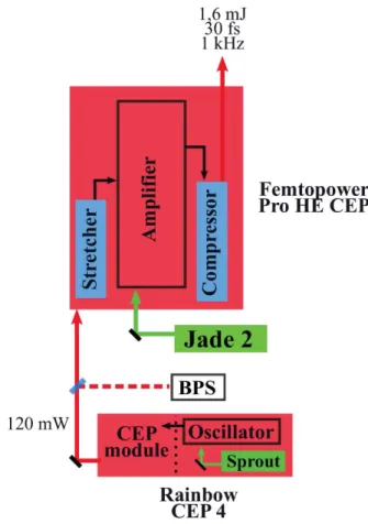
2.3 Layout of the laser
The future Salle Noire 3.0 will be set up in the Bâtiment P, according to the scheme given on Fig. 2.2. This building was not available during my PhD, so that the beginning of the laser chain was in-stalled in the Salle Azzurra.
The first CPA (Rainbow CEP 4 + FemtoPower Pro HE CEP) was bought from the company Fem-toLasers GmbH. This system delivers 1,6 mJ, 30 fs, CEP-stable pulses. Its description and perfor-mance are presented in detail in the next chapter. To enhance the temporal contrast of pulses
from the first CPA, an XPW (Crossed polarized wave generation) setup is inserted before the sec-ond CPA. This temporal filter allows a contrast enhancement of 3 to 4 orders of magnitude and is based on a third order nonlinear process in BaF2crystals. LOA (Laboratoire d’Optique Appliquée)
has a strong know-how with this device which was developed by Olivier Albert and Aurélie Jullien a decade ago [42].
The second CPA is composed of an Öffner-type stretcher [43], a Dazzler for dispersion manage-ment, a Booster which will be manufactured by FemtoLasers GmbH, a home made Power Ampli-fier (PA) and a Transmission Grating Compressor (TGC). This architecture choice will be justified in chapter 4. The post-compression stage, including a Hollow-Core Fiber (HCF) and chirped mir-rors, is supposed to provide 5 fs pulses. Based on our experience in Salle Noire 2.0, we want to totally avoid air propagation of the 25 mJ, 20 fs pulses. Vacuum chambers will be thus installed to house the compressor as well as the post-compression stage. The dashed grey line on Fig. 2.2 indicates the laser chain stages that should be under vacuum.
During my PhD, I have implemented the first CPA in the Salle Azzurra and worked on its exten-sive characterization. The XPW stage and Öffner stretcher were also installed in the framework of this thesis. Because of the undergone delay in other equipments delivery, this is the current status of the construction of the laser. However, I have prepared the implementation of the second CPA by dimensioning calculations and making the technological choices for the key elements of the laser system.
Figure 2.2 – Overview of the future Salle Noire 3.0 in the Bâtiment P. Grey dashed lines mark out the stages under vacuum. BPS: Beam Pointing Stabilization. XPW: Cross-polarized wave generation setup. DZ: Daz-zler.
Front-end performance and
characterization
Contents 3.1 Front-end description . . . 22 3.1.1 Oscillator . . . 22 3.1.2 CEP module . . . 23 3.1.3 First CPA - description . . . 253.2 CEP stabilization performances . . . 26 3.3 Spectro-temporal characterization . . . 27
3.3.1 Best performance in terms of coherent contrast . . . 27 3.3.2 Coherent contrast issues . . . 28 3.3.3 Degradation of the coherent contrast by nonlinear temporal diffraction . . 29 3.3.4 Incoherent contrast measurement . . . 32
3.4 Spatio-temporal coupling . . . 32 3.5 Contrast enhancement of the front-end . . . 39
3.5.1 Setup description . . . 39 3.5.2 Preliminary experimental results . . . 40 3.5.3 Conclusion . . . 40
This chapter is dedicated to the front-end description and characterization. I first describe the oscillator and its CEP stabilization scheme before showing the CPA 1 performances. The differ-ences between the CEP stabilization schemes of the Salle Noire 2.0 and 3.0 are highlighted. Oth-erwise, results from a spatio-temporal coupling characterization of the front-end are presented. To end this chapter, I mention some preliminary results obtained by implementing a nonlinear temporal filter to enhance the front-end contrast.
3.1 Front-end description
The oscillator together with the first CPA form the front-end. This section aims to give a general de-scription of the front-end of the Salle Noire 3.0, which was bought from the company Femtolasers GmbH. The oscillator model is a Rainbow CEP 4, a Kerr-lens mode-locked oscillator including a CEP stabilization device. The first CPA is integrated in a FemtoPower Pro High Energy CEP, includ-ing a stretcher, a multi-pass amplifier and a compressor. A scheme of the front-end is given on Fig. 3.1.
R inbow
CEP 4
Fem opo er
Pro H
CEP
Figure 3.1 – Scheme of the front-end. BPS: Beam Pointing Stabilization.
3.1.1 Oscillator
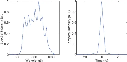
The oscillator delivers pulses with an energy of 3.7 nJ at 75 MHz repetition rate. Mode-locking is achieved by moving quickly an end-cavity mirror so that the continuous mode experiences high losses and the pulsed mode is favored. The oscillator output spectrum is shown on Fig. 3.2(a). The significant spectral modulations are the consequence of amplitude-to-phase coupling in the Ti:Sa crystal due to SPM (Spectral Phase Modulation) processes. Assuming that pulses are FTL, their duration can be estimated via a Fourier Transform, as illustrated on Fig. 3.2(b). The FWHM pulse duration is found to be about 4.6 fs, which is less than 2 optical cycles as the electric field period at 800 nm is 2.6 fs. A CEP measurement and control module follows the oscillator and is part of
the laser. The paragraph below explains in details how works this CEP module and highlights the differences with the conventional CEP stabilization scheme.
600 800 1000 0 0.2 0.4 0.6 0.8 1 Wavelength
Spectral intensity (a.u.)
−20 0 20 0 0.2 0.4 0.6 0.8 1 Time (fs)
Temporal intensity (a.u.)
Figure 3.2 – Typical oscillator output spectrum (a) and corresponding temporal profile calculated via a Fourier Transform (b). The intensity FWHM is 4.6 fs assuming FTL pulses.
3.1.2 CEP module
In a dispersive medium, the carrier wave and the pulses envelope propagate at different velocities. As a result, pulses are CEP-shifted. In a laser cavity, thermal, nonlinear and mechanical insta-bilities in the various dispersive components induce pulse-to-pulse CEP changes, meaning that the resulting pulse train is formed by pulses with different electric field structures. A significant contribution to the pulse-to-pulse CEP change is related to the intensity fluctuations of the pump laser. The CEP is indeed directly affected by the Kerr-induced nonlinear phase in the Ti:Sa crystal, meaning that the pump intensity fluctuations translate into CEP noise.
Carrier Envelope Frequency
A pulses train from an oscillator is described by a frequency comb in spectral domain, with an inter-frequency gap equal to the repetition frequency of the laser, fr ep. The phase noise translates
into a frequency offset according to:
fCE= fr ep
ΦCE
2π (3.1)
whereΦCEis the CEP shift per round-trip and fCEthe carrier envelope frequency. The absolute frequency of the spectral line n of the comb is given by:
fn= n fr ep+ fCE (3.2)
A CEP-shift in the temporal domain reflects thus in a shifted frequency comb in the spectral domain. CEP stabilization can be achieved via fCEmeasurement and stabilization.
CEP measurement in the Rainbow CEP 4
In practice, the CEP drift measurement is achieved in the spectral domain. Among the various existing methods to measure the CEP drift [44], second order nonlinear frequency mixing (Second Harmonic Generation (SHG) or Difference Frequency Generation (DFG)) is usually used. This method requires an octave spanning spectrum and the broadband spectrum from a Ti:Sa based oscillator can be easily extended to a full octave by SPM.
The second harmonic generation of a low-frequency n component of the broadened oscillator spectrum beats with the 2n high-frequency component of the oscillator spectrum. The beating frequency is fCE:
fbeati ng= 2 fn− f2n= 2[n fr ep+ fCE] − [2n fr ep+ fCE] = fCE (3.3)
The same information can be obtained with a DFG process. The only difference is the spectral range of the beat note: a SHG process produces a high-frequency beat note whereas a DFG pro-cess produces a low-frequency beat note. The choice between the two propro-cesses is driven by the highest quantum efficiency of the photo-detector in the considered spectral range [44].
The question of the optical implementation of the CEP measurement device is now discussed. Usually, the beam is split into two arms: one arm allows to measure the CEP drift and the other arm seeds the following of the laser chain or the experiment. However, any reliable phase-locking device will not compensate the phase jitter experienced by the laser pulses after the beam sample for the CEP measurement. A monolithic In-Loop (IL) interferometer scheme was proposed by [45] and has the main advantage of a unique common beam path. In this approach, the CEP measurement and control are performed directly in the beam which is used in the following of the laser chain (or for applications). Besides, using the full power of the oscillator makes the nonlinear process easier.
In the Rainbow CEP 4, the DFG process is achieved in a PPLN crystal inserted in a monolithic IL interferometer, as described above. The full power is used, meaning that the intensity on the PPLN is very close to its damage threshold. The oscillator delivers on a routinely basis between 270 and 290 mW and the maximum acceptable power on the PPLN is about 300 mW so that the seed power of the CEP module should be checked carefully. After the nonlinear wave mixing process, a dichroic mirror selects the infrared beam at the beating frequency fCEwhich is then coupled in a
photodiode.
Conventional stabilization scheme (Salle Noire 2.0 case)
In a conventional scheme, the CEP stabilization process is based on a Phase-Locked Loop (PLL) between fCE and a reference signal given by the oscillator itself. An Acousto-Optic Modulator
(AOM) allows the CEP adjustment via the modulation of the oscillator pump power [46]. This mod-ulation induces indeed a variation of the nonlinear phase-shift experienced by the femtosecond pulses and consequently their CEP. The PLL allows the fCE extraction and frequency-to-voltage
conversion, which is constrained by a maximum error margin and a minimum voltage step [47]. The first constrain makes the PLL not robust (a significant CEP drift will be translated into a voltage higher than the fixed margin, interrupting the PLL). The second constrain limits the PLL sensitiv-ity. A compromise must be found between precision and robustness. Moreover, performing a feedback on the pump laser degrades the oscillator performances in terms of output power, pulse duration and round-trip time. Finally, the PLL technique does not allow to achieve fCE= 0 as it
requires non-zero frequencies for phase comparison. Feed-forward scheme (Salle Noire 3.0 case)
The feed-forward CEP stabilization scheme was proposed in [48] and leads to the generation of a frequency comb at an arbitrary offset frequency fCEwith extremely weak residual phase jitter.
To do so, the free-running oscillator is focused in an Acousto-Optic Frequency Shifter (AOFS) of which the driving frequency corresponds to the amplified CE frequency, fCE(t). As a result, the
1st order diffracted beam at the AOFS output corresponds to a frequency comb down-shifted to exactly zero offset, which is a pulse train exhibiting identical electric field structures. Note that no servo-loop control is involved and the pulse train generation is totally decoupled from the stabi-lization process.
• The oscillator runs free, without any intervention on the intra-cavity power.
• The final frequency comb can be synthesized with an arbitrary offset. A zero offset is achieved feeding the AOFS with fCEfrom the IL interferometer.
• The achievable correction bandwidth is determined by the acoustic delay and is higher than the one in the conventional scheme.
The CEP stabilization of the Rainbow CEP 4 relies on a feed-forward scheme. As explained before, the infrared beam at the beating frequency fCEfrom the IL monolithic interferometer is
measured with a photodiode. Then the beat frequency signal experiences successive filtering and amplification electronic stages before being mixed with a fixed frequency from a RF generator, fRF.
The signal is frequency-shifted to decrease the 1/f noise (the CEP noise is close to zero frequency) and to make the detection easier. Finally, the driving frequency of the AOFS is given by:
fAOFS(t) = fCE(t) + fRF (3.4)
fAOFSis centered at 85 MHz and comprised in a 2 MHz band. A zero offset frequency comb will be
achieved if fRFis a multiple of the repetition frequency of the laser. To keep fCEin the bandwidth
acceptance of the AOFS, a slow feedback is performed by playing on the Ti:Sa crystal temperature. Finally, another slow feedback rectifies any significant CEP drop by playing on intra-cavity wedges. Because of this stabilization scheme, the beam pointing at the CEP module output fluctuates permanently, according to the fluctuations of fCE(t). The 1st order diffracted beam after the AOFS
is indeed orientated by the driving frequency of the AOFS. Therefore, a beam pointing stabilization (BPS) is required at the CEP module output. The front-end was bought without beam pointing stabilization in a first step and the beam deviation made the output power of the amplifier drop from day to day. Realignment was often necessary and the system was unreliable. The integration of a BPS solved this issue. Note that the output power of the CEP module is 120 mW.
3.1.3 First CPA - description
A FemtoPower Pro High Energy CEP is the first CPA, including a bulk stretcher, a 10-pass ampli-fier and a Transmission Gratings Compressor (TGC) (see Fig. 3.1). A detailed scheme is given in Appendix B. Pulses are amplified at 75 MHz repetition rate during the four first passes. Between the 4th and the 5th pass, a Pockels cell reduces the recurrence to 1 kHz. The pulse slicer is located inside the amplifier for contrast issues: seeding the amplifier with the full pulse train for the first passes leads to a more complete extraction of stored energy and so to a reduced ASE level. After the pulse slicer, the average power is reduced so that the Dazzler can be inserted for dispersion management.
The amplifier is pumped by a Nd:YLF-type laser (Jade 2, Thales) delivering 25 W at 1 kHz rep-etition rate. The typical spatial profile of the pump laser within the Ti:Sa crystal has a diameter about 700 µm (1/e2) (see Fig. 3.3). The pump power prior to the crystal chamber is 22 W.
Femtosecond CEP-stable lasers require specific stretcher and compressor designs. Both de-vices are composed of open-space dispersive components, making the propagation of each spec-tral component very sensitive to environment fluctuations. The optical path through both de-vices must be reduced as far as possible, by limiting the stretching ratio and improving their com-pactness. Although their low stretching ratio, bulk stretchers are stable against environmental variations and can efficiently transmit large spectral bandwidths. The GDD introduced by a bulk stretcher can be compensated by a Transmission Grating Compressor (TGC). However, the third order dispersion introduced by the TGC is added to the one introduced by the bulk stretcher, so that a Dazzler is required to manage the third order dispersion. In the FemtoPower, pulses are stretched in bulk to a ten of ps (see the schematic given in Appendix B) and compressed with a TGC. Pulse compression is achieved when the Dazzler settings are typically: 6709 fs, 10000 fs2, -261000 fs3and 290000 fs4. The separation distance between the gratings (1280 gr/mm, Littrow incidence) is 16 mm so that the TGC introduces -75000 fs2and 160000 fs3. In the last pass of the amplifier, the pulse duration is thus about 7 ps. The beam diameter is set to 10 mm before the TGC to avoid nonlinear effects in the gratings bulk. The typical energy of the 30 fs pulses at the FemtoPower output is 1.6 mJ and can be adjusted playing on the amplitude of the Dazzler acous-tic wave. The energy stability is about 2 %RMS and is limited by the pump laser fluctuations (the amplifier is not saturated).
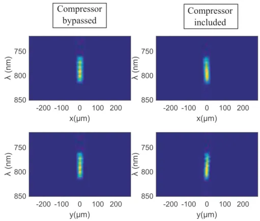
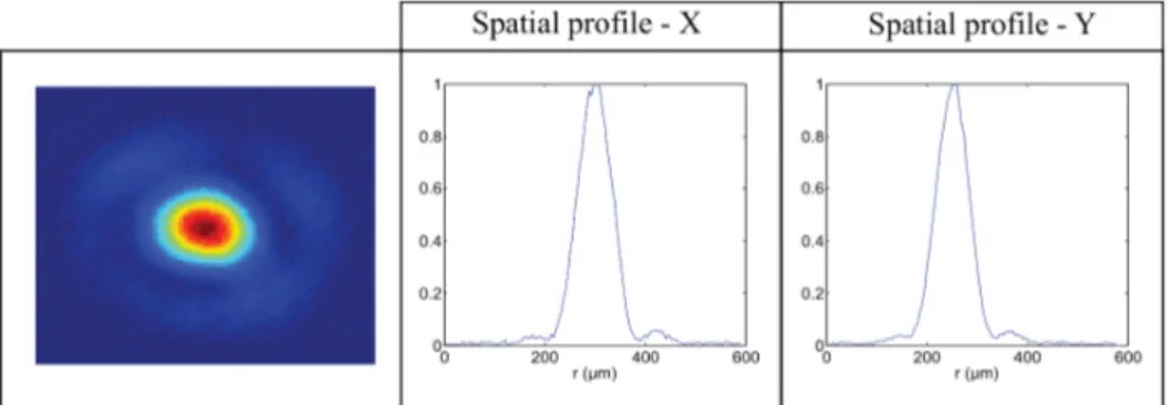
The far field beam profile at the FemtoPower output is shown on Fig. 3.4. A 1 m focal length mirror was used and lead to a beam diameter about 160 µm (1/e2) and an ellipticity of 0,9. This typical beam profile seeded the post-compression setup described in Part 2.
Figure 3.4 – Far-field beam profile at the FemtoPower output.
Finally, the CEP stabilization of the amplified pulses is ensured by the bulk stretcher of which one prism is mounted on piezo-motors (a scheme is given in Appendix A). A commercial f-2f in-terferometer and software (APS) supplied by MenloSystems enabled the CEP noise measurement and stabilization via a slow feedback on the bulk stretcher.
3.2 CEP stabilization performances
To confirm that CEP stability is preserved at the first CPA output, we measured the CEP noise at the FemtoPower output. Data obtained for an integration time of 1 ms and a slow feedback period on the bulk stretcher of 21 ms are shown on Fig. 3.5 and 3.6. The slow loop efficiency is highlighted: the phase noise is decreased by more than 1 order of magnitude for frequencies below 0.1 Hz. The CEP drift is about 190 mrad RMS and is related to the intensity fluctuations of the pump laser and probably also to the temporary thin optical tables.
The CEP stabilization process of the Salle Noire 3.0 laser should be more robust than the Salle Noire 2.0 one. The fast loop (responsible for the oscillator stabilization) provides a feedback on the AOFS which is external to the oscillator cavity, whereas the slow loop (responsible for the laser system stabilization) provides a feedback on the bulk stretcher in the pre-amplifier. The fast and slow feedback are thus decoupled.
This is not the case in Salle Noire 2.0 were both loops control over the oscillator pump power. Such a stabilization system works for limited CEP noises. When upgrading the laser output energy
20 40 60 80 100 −3 −2 −1 0 1 2 3 Time (s) A
veraged phase (rad)
No slow loop 50 100 150 −3 −2 −1 0 1 2 3 Time (s) A
veraged phase (rad)
Slow loop
193 mrad RMS
Figure 3.5 – CEP drift at the FemtoPower output when no loop is activated (left, red) and when a slow loop controls the bulk stretcher (right, blue).
10−2 10−1 100 101 10−1 100 101 102 103 Frequency (Hz)
Phase noise (rad.s)
No slow loop Slow loop
Figure 3.6 – Phase noise when the slow loop is activated or not.
with an additional power amplifier, the CEP noise due to the increased B integral may become too strong to be managed by such a feedback design. This was confirmed by systematic CEP measure-ments at different stages of the laser in Salle Noire 2.0 (this laser system is described in detail in [9]). The results of this CEP campaign are presented in Appendix C and underline the necessity to move to a new CEP stabilization scheme for the Salle Noire 3.0.
In the following, it is shown that B integral is also detrimental to the laser contrast and more generally to the pulse temporal quality, via the experimental spectro- and spatio-temporal char-acterizations of the front-end of the Salle Noire 3.0.
3.3 Spectro-temporal characterization
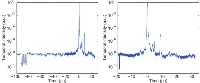
3.3.1 Best performance in terms of coherent contrast
The FemtoPower output pulses were daily measured with a Wizzler device (Fastlite). One of the best performances in terms of coherent contrast is shown on Fig. 3.7: the contrast is 10−4beyond
100 fs. The spectrum measured by the Wizzler device is smooth. A Wizzler-Dazzler loop made the spectral phase flat. In this case, the pulse duration is 33,5 fs.
The spectra recorded before and after the TGC are shown on Fig. 3.8. Both spectra have very similar shape, meaning that negligible nonlinear effects happen in the gratings bulk. Two reflective polarizers were inserted after the compressor to improve the polarization quality of the laser.