HAL Id: tel-02736291
https://pastel.archives-ouvertes.fr/tel-02736291
Submitted on 2 Jun 2020
HAL is a multi-disciplinary open access archive for the deposit and dissemination of sci-entific research documents, whether they are pub-lished or not. The documents may come from teaching and research institutions in France or abroad, or from public or private research centers.
L’archive ouverte pluridisciplinaire HAL, est destinée au dépôt et à la diffusion de documents scientifiques de niveau recherche, publiés ou non, émanant des établissements d’enseignement et de recherche français ou étrangers, des laboratoires publics ou privés.
Méthodologie pour la conception d’espaces de travail
sûrs, avec la collaboration de robot humain
Jose Saenz
To cite this version:
Jose Saenz. Méthodologie pour la conception d’espaces de travail sûrs, avec la collaboration de robot humain. Autre [cs.OH]. Ecole nationale supérieure d’arts et métiers - ENSAM, 2019. Français. �NNT : 2019ENAM0070�. �tel-02736291�
N°: 2009 ENAM XXXX
Arts et Métiers - Campus de Lille
Laboratoire d’Ingenierie des Systèmes Physiques et Numériques
2019-ENAM-0070
École doctorale n° 432 : Sciences des Métiers de l’ingénieur
présentée et soutenue publiquement par
José SAENZ
le 17. Décembre 2019
Méthodologie pour la conception d'espaces de travail sûrs, avec
la collaboration de robot humain
Doctorat
T H È S E
pour obtenir le grade de docteur délivré par
l’École Nationale Supérieure d'Arts et Métiers
Spécialité “ Automatique ”
Directeur de thèse : Olivier GIBARU Co-encadrement de la thèse : Pedro NETO
T
H
È
S
E
JuryM. Marcello PELLICCIARI, Professeur, Università di Modena e Reggio Emilia Président
M. Norbert ELKMANN, Professeur, Otto-von-Guericke Universität Magdeburg Rapporteur
M. Nazih MECHBAL, Professeur, École Nationale Supérieure d’Arts et Métiers Examinateur
M. Olivier GIBARU, Professeur, LISPEN, École Nationale Supérieure d’Arts et Métiers Examinateur
M. Pedro NETO, CORLUC, Universidade de Coimbra Examinateur
2
Methodology for Design of Safe Workspaces featuring
Human Robot Collaboration
byJosé F. Saenz
A dissertation submitted in partial satisfaction of the requirements for the degree of
Doctorate
École Nationale Supérieure d'Arts et Métiers in
Mechanical Engineering
Committee in charge: Professor Olivier Gibaru, Chair Professor Pedro Neto, Co-chair
4
Methodology for Design of Safe Workspaces
featuring Human Robot Collaboration
Copyright 2019 By
i
Abstract
Methodology for Design of Safe Workspaces featuring Human
Robot Collaboration
by
José F. Saenz
Doctorate in Mechanical Engineering École Nationale Supérieure d'Arts et Métiers
Collaborative robotics have a large potential for use in industrial applications. Nevertheless, this potential is currently unrealized and one of the reasons is the challenges in planning and designing while considering the safety requirements of these new types of applications. This thesis focuses on the development of a method for considering the safety aspects of industrial applications featuring human-robot collaboration (HRC applications) during the design phase based on systems engineering, ontologies, an Industry 4.0 concepts. Such HRC applications are characterized by their complexity due to the interdependencies between different system parameters (choice of hardware, parameterization of the system such as sensor range or robot speed) and can be considered system of systems. A review of the current practice for planning and designing HRC applications with a focus on the safety-related aspects was carried out to identify where the current challenges are from the designer’s point of view. An additional review of the state of the art of using systems engineering principles and methods for robotics and safety revealed a large number of past efforts focusing on software engineering, hazard and risk analysis, and ontological development (which underlies all that work). Nevertheless, there were no efforts up to now that focused on the issues that the designer faces with regard to the choice and parameterization of components for HRC applications featuring speed and separation monitoring.
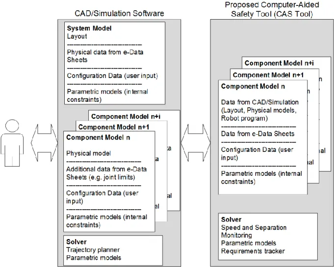
Requirements on a new approach to the consideration of safety based upon the needs of the designer and safety expert were formulated and guided the processes of architecture specification and component modeling that are the focus of this thesis. In particular, reusable models of sensors and robots are necessary in order to have digital information about the application in one place. This allows for easier use and execution of “what-if” analyses that are a part of the design process. An architecture that utilizes existing CAD/simulation tools that designers currently use was specified. The approach was implemented as a computer-aided safety tool (CAS Tool) and the design results were compared with traditional methods with two exemplary use-cases. The use-cases are adapted from real use-cases from the automotive industry.
With the CAS Tool it was possible to quickly make changes to the design, particularly the components such as the robot and safety sensors. The placement of the components and the process itself (i.e. the robot speed) can be easily adapted to achieve specific design goals such as minimum cycle time or minimal footprint of the application. The final outcome was validated against the original set of design requirements, which have been fulfilled. The safety zones calculated with the CAS Tool are up to 66% smaller than with traditional, worst-case methods.
ii
The overall methodology of modeling safety-related attributes of the complete system can have wide-reaching consequences for future robotics applications that are flexible and feature online changes to the program during run-time.
Keywords: human-robot interaction, collaborative robots, safety, systems engineering, industry 4.0
iii
Résumé
Méthodologie pour la conception d'espaces de travail sûrs, avec la
collaboration de robot humain
pour José F. Saenz
Doctorat Mécanique-Matériaux
École Nationale Supérieure d'Arts et Métiers
La robotique collaborative présente un grand potentiel d'utilisation dans les applications industrielles. Ce potentiel est cependant largement inexploité actuellement. L’une des raisons est liée aux difficultés de planification et de conception prenant en compte l’ensemble des des contraintes de sécurité pour ces nouvelles applications. Cette thèse propose le développement scientifique d'une méthode permettant de prendre en compte les aspects de sécurité pour les applications industrielles faisant intervenir la collaboration homme-robot (applications HRC). Cette méthodologie propose de prendre en compte ces enjeux de sécurité dès la phase de conception, sur la base des concepts d'ingénierie des systèmes, d'ontologies et d'Industrie 4.0. Ces applications HRC se caractérisent par leur complexité en raison des interdépendances entre différents paramètres du système (choix du matériel, paramétrage du système, telles que la plage d’utilisation des capteurs ou la vitesse du robot). Elles peuvent être considérées comme des systèmes de systèmes. Une analyse de la pratique actuelle en matière de planification et de conception d’applications HRC tout en mettant l’accent sur les aspects liés à la sécurité, a été effectuée afin de déterminer où se situent les défis scientifiques de conception. L’étude de l'état de l'art en matière d'utilisation des principes et méthodes d'ingénierie des systèmes pour la robotique et de la sécurité a révélé de nombreux efforts passés axés sur l'ingénierie logicielle, l'analyse des dangers et des risques et le développement ontologique. Cependant, aucun effort n'a été consacré au traitement des problèmes concernant le paramétrage des composants pour les applications HRC intégrant une surveillance de la vitesse et de la distance de sécurité.
Les exigences relatives à une nouvelle approche de la prise en compte de la sécurité basée sur les besoins du concepteur et de l'expert en sécurité ont été formulées et ont guidé les processus de spécification d'architecture et de modélisation des composants qui sont au centre de cette thèse. En particulier, des modèles réutilisables de capteurs et de robots sont proposés. Cela facilite l'utilisation et l'exécution d'analyses d’hypothèses faisant partie du processus de conception. Une architecture utilisant les outils de CAD / simulation existants utilisés par les concepteurs a été spécifiée. L'approche a été mise en œuvre sous la forme d'un outil de sécurité assisté par ordinateur nommé CAS Tool. Les résultats de la conception ont été comparés aux méthodes traditionnelles sur deux exemples d'utilisation. Ces cas sont adaptés de cas réels de l'industrie automobile.
Avec notre outil CAS, il est possible de modifier rapidement la conception, en particulier les composants tels que le robot et les capteurs de sécurité. Le placement des composants et le processus lui-même (c'est-à-dire la vitesse du robot) peuvent être facilement adaptés pour atteindre des objectifs de conception spécifiques, tels qu'un temps de cycle minimal ou un encombrement minimum de l'application. Le résultat final a été validé par rapport aux exigences de conception initiales. Les zones de sécurité calculées à l'aide de l'outil CAS sont réduites jusqu'à 66% par rapport aux méthodes traditionnelles les plus défavorables.
iv
La méthodologie globale de modélisation des attributs liés à la sécurité du système complet peut avoir de vastes conséquences pour les applications de robotique futures. L’outil proposé dans cette thèse, résultat de notre analyse scientifique, propose des modifications “en ligne” du programme. Ceci permet une plus grande flexibilité.
Mots clés: Interaction homme-robot, robotique collaborative, sécurité, ingénierie des systèmes, industrie 4.0
v
Table of Contents
1 Introduction ... 1
1.1 Overview of key enabling technologies for collaborative robots ... 2
1.2 Research objectives and contributions ... 3
1.3 Thesis structure ... 4
2 State of the Art... 6
2.1 State of the art for designing HRC applications ... 6
2.2 Example of planning process with current methods ... 10
2.2.1 Starting point: General idea of collaborative application ... 12
2.2.2 Safety oriented design ... 12
2.2.3 General and essential requirements ... 13
2.2.4 Model process, assign tasks ... 13
2.2.5 Define system limits and requirements ... 13
2.2.6 Hazard identification and risk evaluation ... 14
2.2.7 Hazard elimination and risk mitigation ... 14
2.2.8 Review of design ... 15
2.3 State of the art for systems engineering approaches to robotics ... 15
2.3.1 Overview of systems engineering ... 15
2.3.2 Model-based software engineering ... 16
2.3.3 Model-based risk analysis ... 16
2.3.4 SysML systems engineering modeling language ... 17
2.3.5 Ontologies for robotics... 18
2.3.6 Industry 4.0 Framework ... 19
2.4 State of the art for robotic safety and artificial intelligence ... 19
2.5 Discussion on current methods for planning HRC applications... 20
3 Specification of the new approach ... 22
3.1 Requirements specification ... 22
3.1.1 Validity of risk mitigation measures ... 24
3.1.2 Definition of required minimum separation distance ... 24
3.1.3 Validity of sensor positioning in environment ... 25
3.1.4 Changing process parameters to meet specific design targets ... 26
3.2 Architecture specification ... 26
3.3 Novelty of approach ... 28
4 Model development for speed and separation monitoring analysis ... 30
vi
4.2 Overview of available sensors for speed and separation monitoring .... 33
4.3 Model development of laser scanner ... 34
4.4 Model development of light curtain ... 37
4.5 Model development of safety floor mat ... 38
4.6 Model development of projection based workspace monitoring system 39 4.7 Recommendation for sensors to enable HRC ... 41
5 Introduction of exemplary applications ... 43
5.1 Example: de-palletizing robot ... 43
5.1.1 Task description ... 43
5.1.2 Design of de-palletizing HRC application ... 45
5.2 Example: Cleaning machined parts ... 49
5.2.1 General task description ... 50
5.2.2 Design of parts cleaning HRC application with traditional methods 52 6 Use-case studies with exemplary applications ... 59
6.1 Use-case Depalletizing robot ... 59
6.2 Use-case cleaning machined parts ... 64
6.3 Discussion of proposed method ... 69
7 Conclusion ... 73
8 References ... 75
9 Appendix – Example checklists for use during design process ... 81
9.1 Checklist for general and essential requirements ... 81
9.2 Checklist for system limits and requirements ... 82
Disclaimer - the software implementation of the CAS Tool is outside the scope of this thesis and was the work of the Robotic Systems Business Unit of the Fraunhofer IFF. This work makes no claims about the software implementation methods or software development tools used for that implementation.
vii
List of Figures
Figure 1: Examples of HRC applications with different safeguarding modes: A) Power and Force Limiting; B) Hand-guiding; C) Speed and separation monitoring. © Fraunhofer IFF ... 3
Figure 2: Planning industrial application featuring HRC today from the concept to operation ... 7
Figure 3: Flow model of different phases during concept (design) of a HRC application in manufacturing ... 9
Figure 4: Path to CE Mark according to Machinery Directive 2006/42/EC ... 10 Figure 5: Life Cycle Model for HRC applications, based on Generic Life Cycle Model from ISO/IEC/IEEE 15288:2015 ... 10
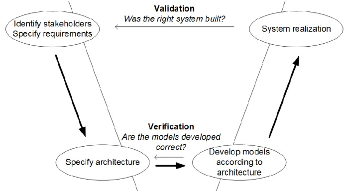
Figure 6: SysML diagram taxonomy [52] ... 18 Figure 7: Schematic overview of the structure of the work in this thesis in adherence to the Vee model ... 22
Figure 8: Schematic drawing showing connection between proposed engineering models, CAD/CAE for design, and real world implementations ... 23
Figure 9: Effect of proposed design and planning approach on workflow for HRC applications, avoiding iterations after the system has been integrated and built ... 24
Figure 10: Layout with robot, two pallets, and a table. The red lines represent the range and angle of view of the two laser scanners placed in the scene. The yellow polygon around the robot represents the required separation distance over the entire robot program. The designer should be able to visually check that the sensor configuration and position is valid. ... 26
Figure 11: Proposed architecture for approach with user interacting with CAD/simulation software and the CAS Tool in the background ... 27
Figure 12: Sequence diagram of the workflow of the designer using existing CAD/Simulation software tools and the proposed Computer-Aided Safety tool ... 28
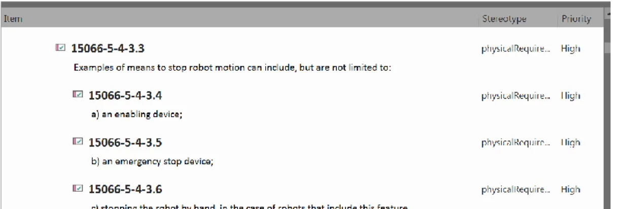
Figure 13: Excerpt of requirements modeled from the ISO-TS 15066 featuring stereotype and priority ... 31
Figure 14: Example of definition of quantity kinds and units in SysML model to ensure compatibility with existing ontologies and standards ... 32
Figure 15: Schematic diagram of projector-based workspace monitoring system 40 Figure 16: Example of the projection based workspace monitoring system: A) no intrusion into safety zone by the operator; B) the intruding hand is detected by the system. © Fraunhofer IFF ... 40
Figure 17: General layout of the depalletizing workspace. ... 44 Figure 18: Layout with robot with minimum required safety distance (R=2918mm) at three main positions for picking and placing with a KUKA KR22 robot operated at maximum speed and using two horizontally oriented laser scanners with a reaction time of 90 ms and a C-value of 850mm. ... 48
Figure 19: Review of the application with a robot and the calculated minimum separation distances using traditional worst-case calculations. The required safety areas reach well into the logistics area, where forklifts pass by. ... 49
Figure 20: General layout of the part cleaning workspace. ... 50 Figure 21: Pathways to bring pallet with parts to each cabinet ... 51 Figure 22: Size of minimum required protective distance for three discreet robot speeds (100% POV, 66% POV, and 33%POV) for a KUKA iiwa 14 robot using two horizontally oriented laser scanners as the safeguarding sensors. ... 56
Figure 23: The calculated safety zones for robots working at cabinets 2 and 3 and the floor space needed to load / unload cabinet 1. ... 57
viii
Figure 24: The calculated safety zones for robots working in cabinets 1 and 3 and the floor space needed to load / unload cabinet 2. ... 57
Figure 25: The calculated safety zones for robots working in cabinets 1 and 2 and the floor space needed to load / unload cabinet 3. ... 58
Figure 26: Screenshots from simulation of robot in application. The yellow polygon represents the minimum required separation distance over the entire programmed path. The red polygon represents the instantaneous required separation distance based on the robot’s current speed at that moment along the programmed path. .... 60
Figure 27: Comparison on separation distance calculated with worst-case assumptions (purple) as three circles at furthest reaching positions and with our approach (yellow polygon) for KR 22 robot with 100% POV and with laser scanner as safety sensor. ... 60
Figure 28: Required separation distance (yellow polygon) around the robot based on a simple program with robot moving to three extreme positions to empty the two pallets and place the parts on the table. ... 61
Figure 29: Final selected configuration with a KR22 robot, 2 light curtains, and 2 fences to limit access to the pallets and the table. ... 62
Figure 30: The designer moved the position of the pallets relative to the robot to reduce the maximum required robot extension. ... 63
Figure 31: The designer used the layout from Figure 29 with a KUKA KR 60 robot instead of the KUKA KR22. ... 63
Figure 32: Required separation distance (yellow polygon) around the robot based on a simple program with robot moving to two extreme positions in the cabinet and ending in its parked position for a laser scanner and 100% POV robot speed. ... 65
Figure 33: Pathway to access station 1, 2 and 3 with laser scanners as the safeguarding sensor and 100% POV robot speed ... 66
Figure 34: Required separation distance (yellow polygon) around the robot based on a simple program with robot moving to two extreme positions in the cabinet and ending in its parked position for the IFF projector based workspace monitoring system and 100% POV robot speed. ... 66
Figure 35: Required separation distance (yellow polygon) around the robot based on a simple program with robot moving to two extreme positions in the cabinet and ending in its parked position for the IFF tactile floor mat and 100% POV robot speed ... 67 Figure 36: Pathway to access station 1, 2 and 3 with projector-based workspace monitoring systems as the safeguarding sensor and 100% POV robot speed ... 68
Figure 37: Pathway to access station 1, 2 and 3 with tactile floor mats as the safeguarding sensor and 100% POV robot speed ... 68
ix
List of Tables
Table 1: Overview of the four modes for safeguarding HRC applications from the
ISO/TS 15066. ... 2
Table 2: Overview of essential components and elements of HRC applications. .. 6
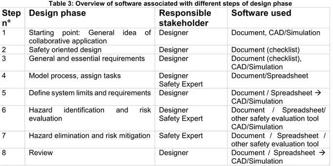
Table 3: Overview of software associated with different steps of design phase .. 21
Table 4. Types of requirements used in SysML, excepted from [63] A Practical Guide to SysML: The Systems Modeling Language. ... 30
Table 5: General attributes for sensors [20] ... 32
Table 6: Excerpt of laser scanner properties from sensor ontology SSN [81] ... 33
Table 7: Overview of attributes for generic laser scanner ... 35
Table 8: Overview of attributes for specific laser scanner SICK microScan3 ... 35
Table 9: Overview of attributes for specific safety laser scanner Hokuyo UAM-05LP ... 36
Table 10: Overview of attributes for a generic light curtain ... 37
Table 11: Overview of attributes for specific safety light curtain SICK C4000 Standard ... 38
Table 12: Overview of attributes for a generic safety floor mat ... 39
Table 13: Overview of attributes for IFF tactile floor mat ... 39
Table 14: Overview of attributes for generic projection based workspace monitoring system ... 41
Table 15: Tabular listing of process tasks for two exemplary processes: standard operation and w operator removal of packing material from the pallet. ... 45
Table 16: Tabular listing of process tasks and associated hazards. ... 47
Table 17: Parameters used to determine size of minimum protective area for a discreet robot position... 48
Table 18: Tabular listing of process tasks standard operation of parts cleaning for a single cabinet ... 53
Table 19: Tabular listing of process tasks and associated hazards. ... 54
Table 20: Parameters used to determine size of minimum protective area for a discreet robot position... 55
Table 21: Comparison of minimum protective distance for different robot speeds ... 55
Table 22: System parameters for four test configurations ... 62
Table 23: Cycle time and size of separation distance around robot for four tested configurations ... 62
Table 24: Comparison of three what-if analyses for depalletizing application ... 64
Table 25: System parameters for comparison of traditional methods and CAS Tool ... 65
Table 26: Horizontal distance between robot and furthest edge of minimum required separation distance for the tested configuration with traditional method and CAS Tool ... 65
Table 27: Comparison of three different safety sensors calculated with CAS Tool for cleaning machined parts use-case ... 67
Table 28: Overview of software used by responsible role during the design phases of an HRC application in manufacturing according to the proposed methodology .... 71
Table 29: Validation of final thesis results against the requirements on the methodology for design of safe HRC applications ... 71
x
Acknowledgements
This work began in 2016 with the idea that there has to be a better way to design collaborative robotics applications than the existing methods. The H2020 funded project “ColRobot” was underway and the planning of the safety-related aspects was slow, iterative, and time-consuming. It was within this project that I first collaborated with Prof. Gibaru and Prof. Neto.
It has since been a long journey from this first idea to the conclusion of this thesis. This work has been the result of close collaborations with my colleagues at the Fraunhofer IFF in Magdeburg, Germany as well as with with Prof. Gibaru and Prof. Neto.
I would like to extend my heartfelt thanks to the IFF team, who aren’t afraid to argue with me and challenge assumptions. I would also like to extend special thanks to Prof. Norbert Elkmann for his support and for creating the working conditions so that I could pursue a doctoral thesis alongside normal work.
I would like to give thanks to Prof. Gibaru and Prof. Neto for their time, their reviews of my work, their patience and motivating words. You both offered the right mix of support and hard deadlines and have pushed me harder than I thought possible. I look forward to future collaboration with you both.
This work is dedicated to my wife and three children who also supported me in this endeavor, gave me time alone to work, and helped me regenerate in our time together. I love you and I promise I won’t try this again.
José Saenz
xi
Acronyms
CAD computer-aided design software is used to design and create mechanical structures
CE mark is a certification mark that indicates conformity with, safety, and environmental protection standards for products sold within the European Economic Area (EEA)
ECAD electronic computer-aided design software is used to design and create electronic structures
EU European Union
FMEA Failure Mode and Effect Analysis
FMECA Failure Modes, Effects and Criticality Analysis HAZOP HAZard Operability
IFR International Federation of Robotics PLC programmable logic controller
POV program override (%) – it is the velocity of the robot motion as a
percentage of the programmed speed vs the maximum possible speed. ROI return of investment
SE systems engineering
SysML systems modeling language is a general-purpose modeling language for systems engineering applications
Résumé Chapitre 1 – Introduction
Récemment, la robotique collaborative a fait des progrès impressionnants, travaillant en toute sécurité côte à côte avec les humains. Cependant, malgré toute l'attention médiatique accordée à ce sujet, il y a relativement peu de robots collaboratifs dans les applications industrielles par rapport aux applications des robots industriels standard [39]. En 2015, les ventes de robots collaboratifs ne représentaient que 1,6 % des 239 000 robots industriels vendus dans le monde [29]. En 2017, dernière année pour laquelle des statistiques sont disponibles, ce pourcentage est passé à environ 4 % des 381 000 robots industriels installés dans le monde [30]. Cela indique qu'en dépit de leur croissance rapide au cours des dernières années, leur potentiel n'a pas encore été pleinement atteint.
Il existe un grand potentiel dans le monde entier pour la réalisation d'applications industrielles faisant appel à la collaboration homme-robot (applications HRC), donnant aux fabricants un moyen d'accroître la productivité, d'améliorer l'ergonomie et la santé des travailleurs et d'améliorer la qualité des composants. Néanmoins, la robotique collaborative n'en est qu'à ses débuts. Ce n'est que maintenant que des limites sont définies en ce qui concerne les collisions entre les humains et les robots [83]. Une fois ces limites mieux connues, les risques seront présentés plus clairement aux travailleurs d'usine et au grand public dans le but de les faire accepter par le plus grand nombre. L'acceptation des travailleurs dans les usines est une question à laquelle les fabricants et les intégrateurs de robots sont très sensibles. Il existe un risque important de réaction défavorable du public si des blessures et/ou des décès surviennent en raison de considérations de sécurité insuffisantes d'un robot collaboratif. C'est pourquoi de nombreux experts de la sécurité dans les usines ont un état d'esprit conservateur.
Pour en revenir à la question du nombre relativement faible de nouvelles installations de robots collaboratifs, l'une des raisons possibles de cette situation est que, malgré la publication récente de normes de sécurité pour la robotique industrielle, les exigences de sécurité strictes posent un défi difficile aux intégrateurs de systèmes et aux concepteurs d'applications robotiques. La planification des applications HRC faisant appel à la collaboration homme-robot (applications HRC) suit actuellement un processus non linéaire et hautement itératif qui présente souvent des inconvénients inattendus. En conséquence, les systèmes complets sont souvent coûteux et leur conception, leur construction et leur validation demandent beaucoup de temps. En outre, l'incertitude qui règne pendant la phase de conception conduit souvent à des situations où un prototype est d'abord construit et validé afin d'arriver à des estimations réalistes des paramètres du processus, ce qui entraîne des coûts supplémentaires.
Un certain nombre de facteurs technologiques importants ont eu lieu qui permettent aux robots de devenir collaboratifs. L'augmentation de la puissance et de la vitesse de calcul, ainsi que les capteurs permettant de détecter l'environnement autour d'un robot ont été des facteurs déterminants. Alors que la première génération de robots industriels était constituée de lourds géants de l'acier déplaçant de grandes masses à grande vitesse mais pratiquement aveugles au monde réel, les robots peuvent utiliser des capteurs de plus en plus sensibles et dotés d'une grande puissance de calcul pour prendre des décisions judicieuses en fonction des images des caméras et d'autres données des capteurs.
L'introduction récente de normes de sécurité pour les robots collaboratifs a contribué à faciliter leur utilisation. Les normes les plus pertinentes pour la sécurité des applications HRC sont les normes ISO 10218-1 et -2, ainsi que la norme ISO-TS 15066. La norme ISO 10218-1 décrit les exigences générales de conception pour la
sécurité des robots industriels destinés à être utilisés dans des applications collaboratives et spécifie la nécessité de systèmes de contrôle de sécurité, qui permettent l'arrêt et la reprise contrôlés des mouvements du robot. L'ISO 10218-2 s'adresse aux intégrateurs de systèmes et décrit les dangers spécifiques à un système complet, les moyens de s'en prémunir et les exigences à respecter lors de la mise sur le marché d'un système. Selon la norme ISO/TS 15066, l'homme doit être protégé contre les dangers dans le cadre d'une opération de collaboration par un mode de protection spécifique. Il existe actuellement quatre modes de protection différents définis dans la spécification technique. Chaque mode comporte des exigences de sécurité spécifiques et une spécification détaillée des mesures de protection obligatoires et des fonctions de sécurité
L'approche adoptée par les trois normes est une acceptation du fait que chaque application est différente et que les questions concernant le processus, le choix des composants de sécurité et leur impact sur l'homme et son travail doivent trouver une réponse spécifique à chaque cas. En aucun cas, les robots collaboratifs ne doivent causer de blessures aux humains travaillant à proximité ou avec eux.
L'objectif général de ce travail est d'étudier comment mieux concevoir, évaluer et assurer la sécurité des applications HRC protégées par la surveillance de la vitesse et de la séparation (SSM). Cela inclut des méthodes pour simplifier la manière de garantir la sécurité lors de la conception, de la planification, de l'évaluation et de la validation de ces applications. Actuellement, il peut s'écouler des années entre la première idée et la validation finale du système, et le processus n'est pas toujours simple.
Les applications comportant un contrôle de la vitesse et de la séparation seront au centre de ce travail en raison de leur pertinence industrielle actuelle. Une étude récente de l'IFR [30] a indirectement souligné l'importance de la MSS en reconnaissant que la majorité des applications du CRH mises en œuvre se caractérisent par une coopération séquentielle. En séparant le robot, ses outils et la pièce de l'homme, le concepteur d'une telle application dispose de plus d'options concernant la géométrie de la pièce, la charge utile du robot et la portée du robot.
Le processus de conception, qui commence dès la première esquisse et se termine avec l'application en cours d'exécution, exige un effort important pour répondre aux exigences de sécurité spécifiées par les normes et réglementations pertinentes. Les intégrateurs de systèmes et les utilisateurs finaux de robots collaboratifs doivent prendre en compte les aspects de sécurité lors de la planification ou après avoir apporté des modifications à leurs systèmes. Les interdépendances entre les opérateurs humains, les composants technologiques (robot, outils, capteurs), l'application (le processus, l'environnement, le rôle de l'homme) et les normes de sécurité sont complexes. Par conséquent, les sous-questions abordées dans cette thèse comprennent:
· Quel est le processus actuel de conception et de prise en compte de la sécurité
des applications HRC?
· D'où viennent les lacunes de ce processus (du point de vue de la sécurité)? · Ces lacunes peuvent-elles être comblées par une nouvelle approche
méthodologique et/ou de nouveaux outils d'ingénierie?
· Quelles sont les exigences relatives à cette nouvelle approche et à quoi peut
ressembler une mise en œuvre?
· Quelles sont les interdépendances entre les différentes parties du système
(homme, robot, outil, environnement, processus, etc.) et comment s'influencent- elles les unes les autres?
· Comment puis-je utiliser cette connaissance des interdépendances pour
· Ces connaissances peuvent-elles être mises à profit?
· Définir sur quoi la recherche future sur les capteurs de sécurité devrait se
concentrer?
Cette thèse est composée de plusieurs chapitres qui présentent l'état de l'art et expliquent ensuite la méthodologie développée pour la prise en compte de la sécurité lors de la planification et de la validation des applications HRC. Le travail est divisé comme suit :
1. État de l'art
2. Exigences et spécification de l'architecture de la nouvelle méthodologie 3. Développement de modèles de capteurs pour la surveillance de la vitesse
et de la séparation
4. Introduction d'applications industrielles exemplaires de CRH
5. Études de cas d'utilisation avec des applications exemplaires et comparaison
État de l'art
Les processus de planification et de prise en compte des exigences de sécurité des applications industrielles faisant appel à la collaboration entre l'homme et le robot comprennent la connaissance des réglementations et des normes pertinentes en matière de robotique, les méthodes d'attribution des tâches entre l'homme et le robot travaillant en collaboration, et les méthodes d'identification des dangers et d'atténuation des risques. L'approche proposée applique des méthodes d'ingénierie des systèmes basées sur des modèles, il sera donc également important de discuter de l'état de l'art pour l'utilisation de l'ingénierie des systèmes en robotique.
Spécification de la nouvelle méthodologie
Dans cette section, les exigences relatives à la nouvelle méthodologie seront définies du point de vue des parties prenantes qui sont actuellement impliquées dans les processus de conception et de mise en service. Ces exigences sur la méthodologie seront utilisées dans une évaluation finale de la méthodologie pour valider si les objectifs de cette thèse ont été atteints.
Sur la base des exigences de la nouvelle méthodologie et en utilisant les concepts d'ingénierie des systèmes, l'architecture de la nouvelle méthodologie sera spécifiée. Cela comprend l'identification des principales composantes et la manière dont elles fonctionneront ensemble afin d'atteindre les résultats souhaités.
Développement de modèles de capteurs pour la surveillance de la vitesse et de la séparation
Un aspect particulièrement important de la méthodologie globale est l'adaptation des modèles de capteurs existants pour inclure des informations liées à la sécurité. Après une première description des aspects de sécurité pertinents en liaison avec le mode de sauvegarde Surveillance de la vitesse et de la séparation, après un aperçu des capteurs qui peuvent être utilisés pour la surveillance de la vitesse et de la séparation, les descriptions des modèles pour un groupe sélectionné de capteurs seront dérivées et expliquées.
Introduction d'applications exemplaires
Dans cette section, deux applications industrielles exemplaires qui sont actuellement réalisées entièrement manuellement seront présentées. L'un des cas d'utilisation comprendra un robot industriel traditionnel avec une charge utile > 15 kg,
et l'autre emploiera un robot léger avec une charge utile <15 kg. Après la description des cas d'utilisation, le processus de conception selon les méthodes traditionnelles sera expliqué pour les deux cas d'utilisation. Ces résultats serviront de référence à laquelle les résultats de la nouvelle méthodologie seront comparés dans la section suivante.
Études de cas d'utilisation avec des applications exemplaires
La méthodologie proposée et la mise en œuvre initiale des outils d'ingénierie qui en découlent seront utilisées pour examiner les deux applications exemplaires présentées dans la section précédente. Une comparaison des résultats et une discussion de la nouvelle méthodologie concluront cette section.
1
1 Introduction
Recently collaborative robotics have been making impressive gains. There have been many reports of new applications featuring them in industrial production, working safely side by side next to humans [25] [26] [27] [28]. However, despite these headlines and all the media attention paid to the subject, there are relatively few collaborative robots in industrial applications compared to standard industrial robots applications [39]. In 2015, sales of collaborative robots were only 1.6% of the 239,000 industrial robots sold worldwide [29]. In 2017, the latest year for which statistics are available, that percentage has risen to approximately 4% of the 381.000 industrial robots installed globally [30]. This indicates that despite their fast growth in the last few years, their full potential has not yet been reached.
Robotics is an important part of manufacturing today, as reflected in the attention and public funding initiatives from different nations worldwide. In Europe, the SPARC Public-Private Partnership [31] was the largest civilian robotics innovation program at the time of its initial contractual agreement on December 2013, with over €700M in funding from the European Commission for the period from 2014-2020. The Made in China 2025 (MIC2025) initiative, announced in 2015, was a strategic plan put forth by the Chinese government [21]. It focused on moving Chinese manufacturing capabilities towards the production of higher value products and services. This covered a large number of fields, from pharmaceuticals to aerospace, automotive, semiconductors, IT, and robotics, and committed roughly $300 billion US dollars to achieve this plan.
There is a large potential worldwide for realizing industrial applications featuring human-robot collaboration (HRC applications), giving manufacturers a means to increase productivity, improve worker ergonomics and health, and improve component quality. Nevertheless, collaborative robotics are still in a very early state. Only now are limits being defined regarding collisions between humans and robots [83]. Once these limits are better known, the risks be more clearly presented to factory workers and the general public with the aim of gaining widespread acceptance. Worker acceptance in factories is an issue that robotics manufacturers and integrators are very sensitive towards. There is a large risk of a public backlash were injuries and/or fatalities to occur due to poor safety considerations of a collaborative robot. This puts many safety experts in factories in a conservative mindset.
Returning to the topic of relatively low numbers of new installations of collaborative robots, one possible reason for this situation is that, despite the recent publication of safety standards for industrial robotics, the strict safety requirements pose a difficult challenge for system integrators and robotics applications designers. Planning HRC applications featuring human-robot collaboration (HRC applications) currently follows a nonlinear and highly iterative process that often features unexpected drawbacks [41, 36, 34, 33, 53, 71]. As a result, the complete systems are often costly and require large amounts of time to design, build, and validate. Furthermore, uncertainty during the design phase often leads to situations where a prototype is first built and validated in order to arrive at realistic estimates for the process parameters, leading to additional costs.
2
1.1 Overview of key enabling technologies for collaborative robots
A number of important technological factors have taken place which allow for robots to become collaborative. Increases in computing power and speed, as well as sensors for detecting the environment around a robot have been driving factors. Where the first generation of industrial robots were heavy steel giants moving large masses at high speeds but practically blind to the real world, robots can use increasingly sensitive sensors with large amounts of computing power to make meaningful decisions based on camera images and other sensor data.
The recent introduction of safety standards for collaborative robots has helped facilitate their usage. The most relevant standards for the safety of HRC applications are the ISO 10218-1 and -2, as well as the ISO-TS 15066. The ISO 10218-1 describes the general design requirements for safety of industrial robots for use in collaborative applications and specifies the need for safety-rated control systems, which allow for controlled stopping and restarting of robot motion. The ISO 10218-2 addresses systems integrators and describes the hazards specific to a complete system, the means for safeguarding against them, and the requirements when introducing a system to the market. According to ISO/TS 15066, the human in a collaborative operation must be protected against hazards through a specific safeguarding mode. Currently there are four different safeguarding modes defined in the technical specification. Each mode has specific safety requirements, and a detailed specification of mandatory protection measures and safety functions. Table 1 offers a brief summary of the four safeguarding modes and Figure 1 shows a few examples of how these safeguarding modes look in practice.
Table 1: Overview of the four modes for safeguarding HRC applications from the ISO/TS 15066.
SAFEGUARDING
MODE DESCRIPTION Safety-rated
monitored stop In this mode, the robot stops before the operator enters the collaborative space. The operator can then enter the collaborative workspace to carry out their intended task. The robot resumes non-collaborative operation and continues its working process only after the operator has exited the collaborative space.
Speed and
separation monitoring The robot system and operator may move concurrently in the collaborative space. Risk reduction is achieved by maintaining a minimum separation distance between operator and robot at all times. This distance is dependent on the speed of the approaching human and the robot, and the robot speed can be varied to maintain the minimum separation distance. When the separation distance decreases to a value below the minimum value, the robot system must in the final instance stop its motion.
Hand-guiding Hand guiding refers to a mode in which motion commands of a hand-operated device are directly transformed into robot motion. In this mode, the robot carries out a safety-rated monitored stop before the operator enters the collaborative space. Then, the intended task is carried out by actuating an appropriate guiding devices manually that is located at or in close proximity to the robot tool.
Power and force
limiting In this mode, physical contact between the robot (and including any physically connected components such as eventual tools and work pieces) and the human is allowed and even necessary to carry out the process properly. Risk reduction is achieved either through inherently safe means or through a safety control system. Collaborative operation with limited robot power and force requires specifically designed robot that are designed for this particular kind of safeguarding mode.
3
Figure 1: Examples of HRC applications with different safeguarding modes: A) Power and Force Limiting; B) Hand-guiding; C) Speed and separation monitoring. © Fraunhofer IFF
The approach taken by all three standards is an acceptance of the fact that every application is different and questions regarding the process, the choice of safety components, and their impact on the human and their work need to be answered specifically for each case. Under no circumstances should collaborative robots cause injuries to humans working near or with them.
1.2 Research objectives and contributions
The overall aim of this work is to investigate how to better design, evaluate and ensure the safety of HRC applications safeguarded by speed and separation monitoring (SSM). This includes methods to simplify how to ensure safety when designing, planning, evaluating, validating such applications. This currently can take years from the first idea to the final system validation and is not always a straightforward process.
Applications featuring speed and separation monitoring will be the focus of this work due to their current industrial relevance. A recent study from the IFR [30] indirectly highlighted the importance of SSM through the recognition that the majority of HRC applications implemented feature sequential cooperation. By separating the robot, its tools and the workpiece from the human, the designer of such an application has more options regarding part geometry, robot payload, and robot reach.
The design process, starting from the first sketch and finishing with the application running, requires a large effort in order to meet the safety requirements as specified by the relevant standards and regulations. System integrators and end-users of collaborative robots need to consider safety aspects when planning or after implementing changes to their systems. The interdependencies between the human operators, the technological components (robot, tools, sensors), the application (the process, the environment, the role of humans) and the safety standards are complex. Therefore, sub-questions addressed in this thesis include:
What is the current design process for designing and considering safety of HRC
applications?
4
Can these shortcomings be addressed through new methodological approach
and/or new engineering tools?
What are the requirements on such a new approach and how can an
implementation look?
What are interdependencies between individual parts of the system (human,
robot, tool, environment, process, etc.) and how do they affect each other?
How can I use this knowledge of the interdependencies to make better designs
and compare alternate designs?
Can this knowledge be leveraged:
- Define where future research on safety sensors should be focused? 1.3 Thesis structure
This thesis is made up of several chapters that present the state of the art and then explain the methodology developed for consideration of the safety during the planning and validation of HRC applications. The work is divided as follows:
1. State of the art
2. Requirements and specification of the architecture of the new methodology 3. Model development of sensors for speed and separation monitoring
4. Introduction of exemplary industrial HRC applications
5. Use-case studies with exemplary applications and comparison
State of the art
The processes of planning and considering safety requirements of industrial applications featuring human robot collaboration includes knowledge of relevant robotics regulations and standards, methods for assigning tasks between humans and robots working collaboratively, and methods for identifying hazards and mitigating risks. The proposed approach applies model-based systems engineering methods, therefore it will also be important to discuss the state of the art for the use of systems engineering in robotics.
Specification of the new methodology
In this section the requirements on the new methodology from the perspective of the stakeholders who are currently involved in the design and commissioning processes will be defined. These requirements on the methodology will be used in a final evaluation of the methodology to validate whether the goals of this thesis have been met.
Based upon the requirements of the new methodology and using systems engineering concepts, the architecture of the new methodology will be specified. This includes the identification of the major components and how they will work together in order to achieve the desired results.
Model development of sensors for speed and separation monitoring
A particularly important aspect of the overall methodology is adaptations to existing models of sensors to include safety-related information. After an initial description of the relevant safety-related aspects in conjunction with the safeguarding mode Speed and Separation Monitoring, After an overview of sensors that can be used for speed and separation monitoring, the model descriptions for a selected group of sensors will be derived and explained.
5
Introduction of exemplary applications
In this section, two exemplary industrial applications that are currently manually executed will be introduced. One use-case will feature a traditional industrial robot with a payload > 15 kg, and the other will employ a lightweight robot with a payload < 15 kg. Following the use-case descriptions, the design process according to traditional methods will be explained for both use-cases. These results will serve as a baseline against which results from the new methodology will be compared in the following section.
Use-case studies with exemplary applications
The proposed methodology and the initial implementation of the engineering tools based upon them will be used to consider the two exemplary applications introduced in the previous section. A comparison of the results and a discussion of the new methodology will conclude this section.
Résumé Chapitre 2 – État de la technique
Dans cette thèse, le terme "robot collaboratif" sera dérivé de la définition de l'ISO 10218 pour le fonctionnement collaboratif, ce qui signifie "...un état dans lequel des robots spécialement désignés travaillent en coopération directe avec un humain dans un espace de travail défini". Un robot collaboratif est donc tout robot industriel utilisé dans le cadre d'une opération collaborative. Cette définition n'impose aucune restriction quant à la forme, la charge utile ou d'autres caractéristiques physiques du robot, mais se concentre sur la manière dont ce robot est utilisé.
Les applications faisant appel à la collaboration homme-robot (applications HRC) consistent en un ensemble spécifique de composants et d'éléments interdépendants. Parmi les plus importants, on trouve l'homme, le robot, le processus, l'environnement, les outils utilisés par le robot, ainsi que des détails concernant l'intégration du système. Ces composants et leurs relations les uns avec les autres constituent l'espace de conception dont disposent les ingénieurs lorsqu'ils créent de nouvelles applications.
Cette section commence par décrire comment les applications HRC sont conçues dans la pratique industrielle actuelle. Le processus de conception, conformément à la directive Machines 2006/42/CE, peut être décrit par un flux de travail qui commence par un concept initial pour une application HRC, et se termine par une description du concept de sécurité final. Les différentes étapes du processus de conception sont les suivantes :
· Idée générale de fonctionnement en collaboration · Conception axée sur la sécurité
· Évaluation des exigences générales et essentielles
· Modéliser le processus, assigner des tâches à l'homme et au robot · Définir les limites et les exigences du système
· Identification des dangers et évaluation des risques · Élimination des dangers et atténuation des risques · Examen de la conception
Cette approche est très itérative et combine l'expertise d'une série de disciplines d'ingénierie distinctes, notamment l'ingénierie mécanique, électrique et de contrôle, ainsi que la santé et la sécurité au travail. Un certain nombre d'outils logiciels sont utilisés, notamment des programmes de CAD ou de simulation, des documents et des feuilles de calcul, avec un flux de données qui n'est pas géré de manière cohérente (par exemple, les données doivent souvent être transférées manuellement d'un système logiciel à un autre, ce qui augmente la marge d'erreur). Certains objectifs de design clés, notamment la dimension au sol, le temps de cycle et les coûts globaux, sont présentés et expliqués.
Après cette description du processus de conception, l'état de l'art des approches d'ingénierie des systèmes en robotique en généralDet de la tâche de conception des applications HRC est examiné. Les principaux thèmes de recherche également étudiés sont l'ingénierie des systèmes, l'ingénierie des systèmes, l'ingénierie des systèmes basée sur des modèles, l'analyse des risques basée sur des modèles pour la robotique, les ontologies et l'industrie 4.0.
L'ingénierie des systèmes (SE) est un domaine largement défini, qui cherche à comprendre les systèmes créés par l'homme en se concentrant sur l'ensemble du système par opposition aux parties [51, 49]. Elle commence par la définition des besoins à un stade précoce et par le rassemblement de différentes disciplines d'ingénierie pour concevoir et valider une solution tout en tenant compte de l'ensemble du problème. Cette approche a été utilisée avec succès pour un certain nombre
d'autres industries présentant un niveau de complexité élevé, notamment la défense [55], l'aérospatiale [56] et l'industrie automobile. Les exemples montrent clairement que la SE est particulièrement bien adaptée à l'analyse d'un système complexe tel que les applications HRC. Dans ce cas, l'application peut être considérée comme un système de systèmes, car les composants de l'application HRC comprennent le robot, ses outils, les senseurs de sécurité et le système de contrôle de sécurité, les opérateurs humains, l'environnement et d'autres systèmes de production (y compris d'autres applications HRC), dont beaucoup peuvent eux-mêmes être représentés comme des systèmes complexes. L'application de la SE peut contribuer à réduire la complexité, permettra une meilleure réutilisation des artefacts d'ingénierie, y compris les programmes. Bien qu'il existe quelques exemples d'application de l'ingénierie des systèmes à la robotique [58], il n'existe aucun exemple connu de son application dans le but de soutenir le développement et la mise en service de la robotique collaborative dans l'industrie dans les phases de conception et de développement du cycle de vie.
Comme les travaux de ce doctorat ont également des implications pour les robots contrôlés par intelligence artificielle, l'état de l'art en matière de sécurité de la robotique industrielle et intelligence artificielle est également brièvement abordé. Les normes les plus importantes pour la sécurité des robots industriels sont analysées pour comprendre comment les robots contrôlés par intelligence artificielle seraient manipulés. L'une des normes harmonisées de type A les plus pertinentes pour la robotique est la norme EN ISO 12100, qui spécifie les principes généraux pour l'évaluation et la réduction des risques. Le concept de comportement déterministe joue ici un rôle important, car l'évaluation des risques doit être concrète et tenir compte des spécifications et des paramètres de fonctionnement du système robotique. Par exemple, la charge utile, la géométrie de la pièce et les conditions environnementales jouent toutes un rôle important dans l'analyse des risques. Un robot transportant des objets tranchants représente un risque différent de celui d'un robot transportant des pièces lourdes ou de petits objets contondants. D'autres paramètres tels que le programme du robot, qui comprend l'enveloppe opérationnelle ainsi que les vitesses du robot, ont une incidence directe sur les paramètres liés à la sécurité, comme la taille de la distance de protection minimale ou la puissance et la force appliquées à une personne en cas de collision.
Les normes ISO 10218-1 et -2, ainsi que la norme ISO/TS 15066 précisent ce qui doit être validé par une mesure après la mise en place physique du système. Les exigences relatives à la validation des fonctions de sécurité, telles que le respect des limites de force et de puissance pour des parties spécifiques du corps, s'appliquent à un programme spécifique. Cette validation se fonde sur le concept de système robotique déterministe, où tous les paramètres et configurations pertinents sont documentés dans l'évaluation des risques. En résumé, les méthodes actuelles pour assurer la sécurité de la robotique collaborative reposent sur le concept de comportement déterministe du robot qui a été programmé par un humain et validé pour fonctionner correctement dans des conditions opérationnelles spécifiques. Ceci est en opposition diamétrale avec les possibilités offertes par l'intelligence artificielle et l'apprentissage machine pour les tâches de perception et de prise de décision. L'approche proposée dans cette thèse cherche à améliorer cette situation en fournissant un moyen de valider en simulation la sécurité d'applications spécifiques. Un effet secondaire de cette approche est que la validation pourrait également être utilisée pour les applications HRC qui impliquent des programmes définis par l'IA.
· Différents outils logiciels d'analyse. L'outil de CAD / simulation est le principal moteur du processus de développement, mais du point de vue de la sécurité, de nombreuses questions restent sans réponse. Passer d'un outil logiciel à l'autre (voir la vue d'ensemble dans le tableau 3) implique le transfert manuel de données de l'un à l'autre, ce qui entraîne des erreurs et des incohérences dans les données du système.
· Le processus est extrêmement itératif, en raison de la complexité et des options dont dispose le concepteur. Cela signifie qu'il n'y a aucun moyen de savoir si la solution est la meilleure, et la comparaison des solutions implique de nombreux ensembles de données différents qui deviennent difficiles à manipuler. Si le concepteur décide d'utiliser une combinaison de clôtures et de scanners, ou de clôtures et de rideaux lumineux, tous les calculs et hypothèses faits lors des phases de conception précédentes doivent être revus. Cela implique de s'entretenir avec des collègues ayant des compétences différentes (par exemple, en parlant avec des experts en capteurs, des experts en sécurité). Un changement à un endroit peut avoir de graves conséquences du point de vue de la sécurité.
· Les méthodes de calcul de la distance minimale de séparation requise sont limitées. Les calculs actuels sont basés sur les hypothèses les plus pessimistes et ne reflètent pas la réalité du système. La validation des hypothèses nécessite des mesures, ce qui signifie que le matériel doit être mis en place avant que le concepteur puisse être sûr que les objectifs de conception ont été atteints. En outre, les hypothèses peuvent facilement changer et les interdépendances peuvent facilement être négligées. Enfin, l'utilisation des hypothèses les plus pessimistes pour l'ensemble du programme de robot, bien que facile à gérer et à comprendre, peut conduire à de faibles performances et à des vitesses de robot plus faibles que nécessaire.
Le travail décrit dans cette thèse est basé sur l'approche de l'ingénierie des systèmes. Cette approche a été choisie parce que l'ingénierie des systèmes est capable de soutenir différentes disciplines d'ingénierie pour concevoir et valider des solutions. Elle se concentre sur l'ensemble du système. Elle a été appliquée avec succès à une série d'industries comportant des systèmes complexes (par exemple, l'aérospatiale, le secteur militaire, l'automobile) et est applicable aux applications HRC. Celles-ci peuvent être considérées comme un système de systèmes, car elles consistent en une combinaison de composants individuels comprenant le robot, ses outils, les capteurs de sécurité et le système de contrôle de sécurité, les opérateurs humains, l'environnement et d'autres systèmes de production (y compris d'autres applications HRC), dont beaucoup peuvent eux-mêmes être représentés comme des systèmes complexes.
6
2 State of the Art
The term collaborative robotics itself has become a source of confusion. The International Federation of Robots distinguishes between two types of collaborative robots, namely those that were specifically designed for collaborative operation in compliance with the ISO 10218-1, and those that were not [30]. Often the term “cobot” is used in popular science articles to refer to a class of lightweight robots that typically a low payload (max. 14 kg) and that were designed for allowing contact with humans under certain circumstances. In this thesis the term collaborative robot will be derived from the ISO 10218 definition for collaborative operation, meaning “…a state in which purposely designed robots work in direct cooperation with a human within a defined workspace.” A collaborative robot is therefore any industrial robot used in collaborative operation. This definition does not place restrictions on the form, payload, or other physical characteristics of the robot, but focuses on how it is used.
2.1 State of the art for designing HRC applications
In general, a HRC application consists of a specific set of the components and elements as shown in Table 2.
Table 2: Overview of essential components and elements of HRC applications.
COMPONENT /
ELEMENT DESCRIPTION
Human This refers to any human who could be involved in the collaborative working area, from the operator to logistics personnel or bystanders passing through. Robot The robot working in the HRC application, regardless of how it is
safeguarded.
Tool The tool used by the robot to fulfil its intended tasks. This can range from a gripper for material handling to tools for processing mechanical parts and also includes tool-changers
Environment The environment includes elements belonging to the working space such as fixtures, building structures, pathways, etc.
Process The process refers both to the parts used in the intended tasks as well other aspects for the execution of the intended robot action such as required robot speeds or forces.
System
integration The term system integration refers to all components that are required for the implementation of the HRC application, including safety sensors, and PLCs.
These components and elements represent the design space that an engineer has available when designing a new HRC application. These components and elements exhibit a large number of interdependencies on each other, i.e. a change to one component can have a large effect on other elements. Additionally, the HRC applications designer needs to respect a number of requirements and constraints on the task, the environment, and human health and safety.
In industry, there are a number of domain specific tools for designing collaborative robotics applications. The standard method consists of a project manager working with mechanical and electrical engineers. The mechanical engineers work in CAD, possibly with a robotics simulation environment. They model the overall layout, the material flow, and define the type of collaboration with the human by also defining the human’s tasks. They check that the initial requirements are met and choose the robot type based on a few criteria such as payload, reach, and specific customer preferences. The electrical system can be designed in an electrical computer aided design (ECAD) program. There is usually no direct digital connection between the mechanical and electrical domains. Electrical components are physically modeled and the cable paths are considered by the mechanical engineers. Logical pathways, communication, and
7
electrical energy can be modeled in the ECAD. Once the system is physically ready, the programmer can begin the process of programming the robot. They rely on a variety of tools and middlewares, and can sometimes use the simulation built beforehand for their purposes.
The project manager oversees all sides and ensures that the status is compatible and that any updates or changes are communicated so that each individual team can update their individual models.
Usually the safety for a collaborative robotic application is important, and either an extra safety expert is brought into regular meetings or a member of one of the existing teams (electrical or mechanical). There are a number of dedicated tools such as Sistema [73] which support the choice of the electrical components and help ensure conformity according to functional safety standard ISO 13849-1.
Looking at this, we can see that the engineering tools are fragmented. Any questions regarding “what-if” scenarios involve teams of people with competing interests, unclear requirements, and unclear means of ensuring that an optimal goal is reached. This is a particular challenge with HRC applications, which feature a large number of actors and components with many interdependencies that cannot be easily managed.
Figure 2 illustrates the planning process as it is carried out today. Starting from a concept and moving to productive operation with the HRC application, the iterative nature of the step “replanning” due to unfulfilled safety requirements can insert uncertainty into the process of designing, building, and operating an application featuring HRC, both in terms of time to completion and outcome.
Figure 2: Planning industrial application featuring HRC today from the concept to operation
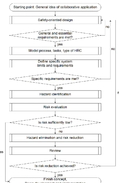
Figure 3 takes a closer look at the individual steps involved in the planning phase. In this diagram, the starting point is a general idea of collaborative application, meaning that the industrial application, which will feature a collaborative robot is well known, and that there is a rough idea of how the robot should assist the human operator. This also means that an initial choice for the type of robot (type, payload, size, position) has been made, as well as an initial layout plan for how the robot should be positioned in the environment. Previous work [17, 48] describes a decision-making framework for generating the layout of an HRC application and allocating tasks between robots and humans, with the aim in reducing the time and effort for generating a process plan. While these questions are valid and the methods they propose are sound, their work is less relevant for the safety-related considerations of the layout. Other research in this field [45] focuses on describing robot motions as small building blocks and then combining these for planning assembly tasks. While this work provides an interesting overview of the state of the art for robot assembly planning, this approach does not consider safety in the sense of ISO 10218-1 and -2 and is only peripherally relevant for this work.
8
Following this starting point, a safety oriented design is carried out. The concrete details of the design are then cross-references to ensure that the general and essential reqirements are met (e.g. do all safety components have Performance Level “d”, Category 3, etc.). Only once the general requirements (from the 10218-1) are met, does it make sense to look deeper at the process and to start detailing it, defining specifically which are done by the robot and which by the human, and what kind of HRC is envisioned (as well as the corresponding safeguarding mode) for different steps. Following this, the system limits need to be defined (e.g. where are no-go areas for the robot, what are max robot speeds, etc.), and then a check whether the specific application requirements are met (is the system fast enough to complete it in the cycle time). After the requirements have been met, a hazard identification and risk evaluation are carried out. By this time, the design is quite advanced and it is possible to identify real, specific hazards. Therefore, instead of high-level hazard such as “Possible clamping of human body parts between robot and environment”, a specific one would be “Possible clamping human hand and upper arm between robot gripper and part carrier during process x, and again during process y.” Should certain risks be considered too high, a hazard elimination and risk reduction needs to be carried out. This can be achieved for example through additional safety sensors, through changes to the process, the environment, and/or the material flows. Here quite a lot of work has focused on applying different safeguarding techniques [16, 34, 44], and on methods for calculating the required safety distances [50, 34, 16, 33, 10]. Due to the sheer number of options the designer has at their disposal to adapt an HRC application, there are a large number of possible variations for a given application. Furthermore, as indicated in the flow chart, if the final system still poses significant safety risks to the humans, the designer has to start all over again. The concept is only complete once the risk has been sufficiently reduced, opening the path for further development for implementation.
9
Figure 3: Flow model of different phases during concept (design) of a HRC application in manufacturing
In addition to the tasks involved in planning the HRC application, the designer also needs to consider the required steps to attain a CE mark [11]. Figure 4 shows the typical steps involved in this process. The engineering tools proposed in this thesis support designers in these tasks specifically during the steps “verify product specific requirements,” as well as “test the product and check its conformity”.


![Table 6: Excerpt of laser scanner properties from sensor ontology SSN [81]](https://thumb-eu.123doks.com/thumbv2/123doknet/2856834.71107/66.891.118.524.345.715/table-excerpt-laser-scanner-properties-sensor-ontology-ssn.webp)
