TH `ESE
TH `ESE
En vue de l’obtention du
DOCTORAT DE L’UNIVERSIT´E DE TOULOUSE
D´elivr´e par : l’Universit´e Toulouse 3 Paul Sabatier (UT3 Paul Sabatier)
Pr´esent´ee et soutenue le 21/07/2015 par : Yingying GU
Membranes polym`eres fonctionnalis´ees par des poly(liquide ionique)s et des nanoparticules de palladium: applications au captage de CO2 et aux
membranes catalytiques
JURY
Eric Favre Professeur des Universit´es
(LRGP, ENSIC, Nancy) Rapporteur Laurent Djakovitch Directeur de recherche CNRS
(IRCELYON) Rapporteur
Th´eodore Tzedakis Professeur des Universit´es
(LGC, U. Toulouse III) Président du Jury Jean-Christophe Remigy Maitre de conférences, HDR
(LGC, U. Toulouse III) Membre du Jury Montserrat G´omez Professeur des Universit´es
(LHFA, U. Toulouse III) Invitée Richard D. Noble Professeur de University of
Colorado, Boulder, USA Invité
´Ecole doctorale et sp´ecialit´e :
MEGEP : G´enie des proc´ed´es et de l’Environnement
Unit´e de Recherche :
Laboratoire de G´enie Chimique - CNRS (UMR 5503)
Directeur(s) de Th`ese :
Acknowledgements
In the very first place of this thesis, I would like to give my sincere acknowledge-ments to all those who have made contributions or support for this work. There are just too many people to thank to.
I express my deep gratitude to my supervisor Jean-Christophe Remigy for his en-lightening guidance and great support throughout the whole thesis project and for the enough freedom that he accorded to me to explore the subject. I would also like to deliver my most sincere thankfulness to all the co-supervisors : Jean-François Lahitte, Montserrat G´omez, Richard D. Noble and Douglas L. Gin for their valuable instructions, availability, huge support and personal help. Without them, this project coud not be a success.
I deeply appreciate Professor Eric Favre and Laurent Djakovitch, research director at IRCELYON for having accepted to evaluate this thesis and for their valuable advices. I’m also grateful to the Ministère de l’Enseignement Supérieur et de la Recherche for providing financial support for the thesis.
My warm thanks also go to Pierre Aimar, Jean-Christophe Rouch, Sandrine De-sclaux, Laure Latapie, Isabelle Favier, Emmanuelle Teuma, Christian Pradel, Patrice Bacchin and Hans H Funke for their useful help on the research work and their willing-ness to do so. I would like to thank Patrice Bacchin again, Hélène Roux-de Balmann, Régine Legoff and Naïma Khoujane as well for giving supports and helps on all the ad-ministrative work. Besides, I owe my thanks to Christel Causserand for her constructive comments on the 2nd year report and to Catherine Stasiulis for her great help on the application of carte de séjour.
In addition, I would like to address my gratefulness to Clélia Emin, Elsa Lasseuguette, Faouzi Chahdoura, Thibaut Savart, Marta Rodriguez Rodriguez, Antonio Reina Tapia, Marcelo, Lee Miller, Nathaniel Urban, Matthew Cowan, William McDanel, Blain Carter, Phuc Tien Nguyen, Lilly Robertson, Sarah Dischinger and my friends for their friend-liness, their help in the research and for having created the warm and joyful ambience around.
At last, I would like to dedicate this thesis in memory of my parents. Their love and support are beyond expression.
Contents
General introduction 5
1 Bibliographic study 9
1.1 General introduction on synthetic membranes . . . 12
1.1.1 Membrane classification and corresponding separation processes concerned . . . 12
1.1.2 Membrane performance evaluation . . . 13
1.1.3 Transport mechanism through membranes . . . 17
1.1.4 Filtration mode and module configurations . . . 20
1.2 Preparation of composite polymer membranes . . . 22
1.3 Membrane for CO2 capture . . . 25
1.3.1 Basic types of CO2 capture . . . 25
1.3.2 Polymer membranes for CO2 capture . . . 25
1.3.3 CO2 plasticization and competitive sorption in polymer membranes 31 1.4 Process intensification . . . 34
1.4.1 Microreactors . . . 36
1.4.2 Catalytic membrane reactors . . . 36
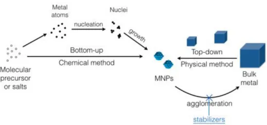
1.5 Metallic nanoparticles (MNPs) in catalysis . . . 39
1.5.1 Synthesis of MNPs . . . 40
1.5.2 Mechanisms of nanoparticle formation . . . 41
1.5.3 Stabilization of MNPs . . . 42
1.5.4 Polymer swelling by solvent and mass transfer inside polymer ma-trices . . . 44
1.6 Ionic liquids for CO2 capture and MNP stabilization . . . 47
1.6.1 RTILs for MNP stabilization . . . 47
1.6.2 RTILs for CO2 capture . . . 49
1.7 Conclusions . . . 50
2 Materials and methods 53 2.1 General . . . 56
2.1.1 Materials . . . 56
2.2 Modification of hollow fibers by room temperature ionic liquids for CO2
capture . . . 57
2.2.1 Composite hollow fiber preparation . . . 57
2.2.2 Gas permeance test for composite hollow fibers . . . 59
2.2.3 Experimental conditions for tensile test . . . 60
2.3 Preparation of colloidal palladium systems and their catalytic performance 60 2.3.1 Synthesis of colloidal palladium nanoparticles in ionic liquid . . . . 60
2.3.2 Synthesis of colloidal palladium nanoparticles in glycerol . . . 60
2.3.3 Catalytic tests on the colloidal systems . . . 61
2.4 Preparation, characterization and performance of the catalytic membrane 62 2.4.1 Synthesis of ionic liquids a and b . . . 62
2.4.2 ICP-OES analyses . . . 64
2.4.3 Preparation of the catalytic membrane . . . 65
2.4.4 Permeability test . . . 65
2.4.5 Reactions performed on the catalytic membrane . . . 66
2.4.6 Colloidal palladium stabilized in glycerol served as reference for more challenging reactions . . . 68
3 Preparation of composite hollow fiber with a thin polyRTIL-RTIL gel layer for CO2 capture 69 3.1 Introduction . . . 72
3.2 General Information . . . 73
3.2.1 Ionic liquids concerned and their gas permeability . . . 73
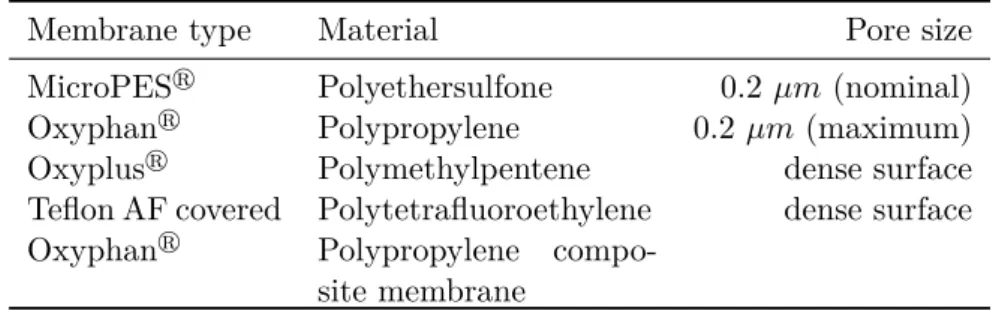
3.2.2 Support membranes . . . 74
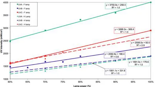
3.2.3 UV Lamp and optical filter type . . . 75
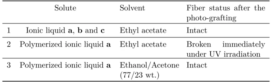
3.3 Influential factors in photo-grafting and composite membrane performance 75 3.3.1 Compatibility between the support membrane and the grafting solution — General considerations on solvent choice . . . 76
3.3.2 Diffusion of the monomers into the support membrane pores — Oxyphanr as support membrane . . . 80
3.3.3 Wetting of the support membrane surface — Teflon AF covered Oxyphan as support membrane . . . 85
3.3.4 Gas separation performance and influence of monomer concentra-tion and fiber velocity — Oxyplusr as support membrane . . . 89
3.3.5 IL monomer type . . . 99
3.4 Conclusions . . . 101
4 Study of the catalytic behavior of palladium nanoparticles dispersed in liquid phase 105 4.1 Introduction . . . 108
4.2 Synthesis of colloidal PdNPs . . . 108
4.3 Catalytic study in [MMPIM][NTf2] under batch conditions . . . 112
4.3.1 Pd-catalyzed hydrogenation reactions . . . 112
4.3.3 Pd-catalyzed cross-coupling/hydrogenation sequential process . . . 121
4.4 Catalytic study in glycerol — Exploration of other solvents with physico-chemical properties close to RTILs . . . 122
4.5 Conclusions . . . 123
5 Catalytic polymeric membrane containing palladium nanoparticles 125 5.1 Introduction . . . 128
5.2 Preparation and characterization of the catalytic membrane . . . 129
5.2.1 Choice and synthesis of imidazolium-based ionic liquids . . . 129
5.2.2 Preparation of the catalytic membrane . . . 129
5.2.3 Characterization of the catalytic membrane . . . 130
5.3 Comparison of catalytic activity between the catalytic membrane and the colloidal PdNPs in batch reactor on Suzuki-Miyaura cross-coupling reaction137 5.3.1 Catalytic performance of the colloidal PdNPs in the batch reactor 137 5.3.2 Performance of the catalytic membrane . . . 140
5.4 Catalytic performance of the catalytic membrane on other reactions . . . 150
5.4.1 Hydrogenation . . . 150
5.4.2 More challenging reactions . . . 152
5.5 Conclusions . . . 154
6 Extrapolation of the catalytic membrane for exothermic reactions and industrial-scale applications 157 6.1 Introduction . . . 162
6.2 Fluid dynamics and concentration profile inside membrane pores . . . 162
6.3 The catalytic membrane for exothermic reactions . . . 164
6.3.1 Reactor model . . . 165
6.3.2 Heat transfer coefficient and Nusselt number . . . 169
6.3.3 Flow rate and heat transfer P´eclet number . . . 170
6.3.4 Temperature profile and Stanton number . . . 170
6.3.5 Reactor temperature and external Stanton number . . . 172
6.3.6 Case study . . . 173
6.4 Potential for industrial-scale production . . . 175
6.4.1 Reactor configurations and corresponding working points . . . 176
6.4.2 Considerations on boundary layer and filtration mode . . . 179
6.4.3 Production capacity of the membrane reactor and estimation on the cost of palladium . . . 181
6.5 Conclusions . . . 184
Conclusions and perspectives 187 References . . . 192
Background and research interest
Systematic studies of membrane phenomena can be traced to the eighteenth century philosopher scientists. For example, Abb´e Nolet coined the word ‘osmosis’ to describe permeation of water through a diaphragm in 1748 [1]. By 1960, the elements of mod-ern membrane science had been developed, but membranes were used in only a few laboratory and small, specialized industrial applications (e.g. desalination, dairy indus-try) [2,3]. While nowadays, membranes and membrane processes have gained important lace in chemical technology and are used in a broad range of applications. The fast development of membrane based processes in the last few decades are undoubtedly re-lated to their attractive properties such as low energy cost and environment impact, low weight and space requirements and good modularity, etc. Those unique characteristics permit membrane processes to achieve extraordinary levels of process intensification, a possible solution to the crucial challenges currently facing the world: sustainable indus-trial growth [4].
Our research lies within the concept of process intensification and sustainable devel-opment, with major interest in the advanced functionalization of polymer membranes. The work presented in the thesis concerns the development of two membrane processes: one for CO2 capture (contributing to global climate change mitigation), one for
cata-lytic membrane (in the pursuit of high productivity/reactor volume ratio and energy efficiency).
Motivations and objectives
Membrane based CO2separation processes have advantages mainly in terms of high
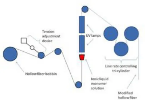
energy efficiency over other gas separation processes. And the use of room temperature ionic liquids (RTILs) in/as membranes are receiving growing attention. Two major ap-proaches are involved: Supported ionic liquid membranes (SILMs) and dense membranes made form polyRTILs. Recently, a new approach combining the two above – polyRTIL containing RTILs, has witnessed substantial research interest [4–9]. However, most of the studies concerning polyRTIL-RTIL composite membranes are based on lab-scaled flat sheet membranes of small surface area. One of the objectives of this work is to fab-ricate continuously hollow fibers functionalized by a thin top layer of polyRTIL-RTIL. This modification can further increase the gas permeance and membrane area/surface ratio and thus improve the overall gas separation performance of the membrane. But this modification is generally not feasible using coating or extrusion processes. Herein, we seek to prepare such a composite hollow fiber using photo-grafting process. Success in doing so will be a step further for the innovative lab made membrane materials towards industrial-scale applications.
Concerning catalytic membranes, the most studied up to now are based on inor-ganic materials (metals or ceramics). Much less attention has been paid to polymeric membranes. Although largely cheaper than inorganic counterparts, polymeric mem-branes suffer from limited thermal stability (They can only be used at temperatures inferior to 200 ¶C). It’s true that inorganic catalytic membranes are more adapted for
is unnecessary? What advantages can polymeric catalytic membranes bring out? How efficient can they be? We try to find answers to those questions in this work. In this pursuit, we prepared a polymeric catalytic membrane (containing palladium nanoparti-cles (PdNPs) as catalyst) and studied its catalytic performance in order to figure out its mechanism (mass transfer, reactivity) and to compare its performance with that of batch reactors.
Organization of the thesis
Chapter 1 provides a bibliography background of the study. Basic notions and state-of-art of CO2capture and of catalytic membrane reactors are introduced. Chapter
2 assembles all the experimental analysis and protocols involved. Chapter 3 deals with the results on polyRTIL based composite hollow fibers for CO2/N2separation. Study on
the obtained fiber permeation performance and on the influence of various experimental parameters are presented. Criteria on the choice of materials (i.e. support membrane, solvent). Chapter 4 describes the preparation of an active palladium nanoparticle col-loidal system (NPs dispersed in ionic liquid) and their catalytic activity under batch conditions. This colloidal system was used later on to compare with the catalytic mem-brane, particularly in terms of activity. Chapter 5 comprises a comprehensive study on the catalytic membrane: from preparation methods, study of the NPs dispersion inside the membrane to its catalytic performance. Theoretical calculations were effectuated to understand the origin of the efficiency of the catalytic membrane. Chapter 6 explores through calculations the potential of the catalytic membrane for exothermic reactions and industrial applications.
Chapter 1
R´esum´e du Chapitre
Ce chapitre donne le contexte de l?étude et l’état de l’art qui servent à faciliter la compréhension de cette thèse. Les notions sur les membranes et leurs préparations sont présentées en premier, suivi par les procédés membranaires appliquées au captage de CO2. Les membranes catalytiques et les principes d’intensification correspondantes sont
ensuite discutées. La synthèse et la stabilisation des nanoparticules métalliques sont également élaborées. Pour terminer, une brève revue sur des applications des liquides ioniques à température ambiante pour le captage de CO2 et leur utilisation pour
sta-biliser les nanoparticules métalliques est présentée.
Ces travaux combinent les avantages des procédés membranaires (compacité élevée), des liquides ioniques à température ambiante (avec nombreuses applications et un grand potentiel) et des nanoparticules métalliques qui sont très actives, afin d’obtenir une intensification remarquable des procédés. Notre étude bibliographique est basée non seulement sur des connaissances existantes mais aussi sur leur évolution récente pour le captage de CO2 par des membranes fibres creuses (décrit dans Chapitre 3) et pour les
This chapter provides a background and state-of-art study that serves as a fun-damental basis for the understanding of the thesis. Notions on membranes and their preparation are introduced in the first place, followed by membrane-based applications on CO2 capture. Then the classification of catalytic membranes and the corresponding
intensification principles are discussed, succeeded by elaborations on the synthesis and stabilization of metallic nanoparticles (MNPs). Brief reviews on applications room tem-perature ionic liquids in CO2 capture and MNP stabilization are given in the last part.
This thesis combines the ‘membrane processes’ (featuring a high compactness), room-temperature ionic liquids (with wide applications and enormous potential) together with the highly active MNPs in the pursuit of outstanding process intensification. This research is based on the existing knowledge and recent developments as illustrated in this chapter for the realization of the innovative CO2 capture hollow fiber membrane
(elaborated in Chapter 3) and a polymeric catalytic membrane (Chapter 5 and 6).
1.1 General introduction on synthetic membranes
1.1.1 Membrane classification and corresponding separation processes concerned
A membrane can essentially be defined as a barrier that separates two phases and se-lectively restricts the transport of various chemicals [2]. Membrane based processes have found their wide applications in various domains such as chemical, food, and pharmaceu-tical industries, biotechnology, and the treatment of toxic industrial effluents, etc [2,10], thanks to the following advantages [11]:
- Appreciable energy savings - Environmentally benign
- Clean technology with scale-up and operational ease
- Substitution of conventional processes such as filtration, distillation, ion-exchange and chemical treatment systems
- High quality products
- Greater flexibility in system design.
Membranes can be classified by the type of material (organic, polymeric, inorganic, metallic, etc.) the membrane is made from and also according to the pore size. Accord-ing to the IUPAC classification, porous membranes with average pore diameters larger than 50 nm are classified as macroporous, and those with average pore diameters in the intermediate range between 2 and 50 nm as mesoporous; microporous membranes have average pore diameters which are smaller than 2 nm. Current membrane processes (classified by pore size) include: [12]
1. Microfiltration (MF, pore sizes ranging from 0.03 to 10 µm) : mainly used for the removal of large particulates, colloids, and bacteria from feed streams; especially popular in the food and beverage industry for treating wastewater before discharging it
to a municipal sewer.
2. Ultrafiltration (UF, pore sizes ranging from 0.002 to 0.1 µm): used in rejecting viruses and polypeptides, and are widely used in protein concentration and wastewater treatment.
3. Nanofiltration (NF, pore size on the order of 1 nm): Nanofiltration membranes are similar to reverse osmosis membranes in that they contain a thin-film composite layer (<1 µm) on top of a porous layer (50 to 150 µm) for small ion selectivity. NF membranes are able to reject multivalent salts and uncharged solutes, while allowing some monovalent salts to pass through. It is often used to soften hard water.
4. Reverse osmosis (RO, pore size around 0.1 nm or dense membranes ): Reverse osmosis membranes are even tighter than nanofiltration membranes, and are able to reject all monovalent ions while allowing water molecules to pass through in aqueous solutions. They can also remove viruses and bacteria found in feed solutions. Common applications for reverse osmosis filtration include seawater desalination and industrial water treatment. It is important to note that since the operating pressure for RO and NF is much higher than the pressure applied by MF and UF, the overall yield is rela-tively lower than that of MF and UF membranes.
5. Pervaporation (PV, dense membranes in general): Pervaporation is recognized as a separation process in which a binary or multicomponent liquid mixture is separated by partial vaporization through a dense membrane. During pervaporation, the feed mixture is in direct contact with one side of the membrane whereas the permeate is removed in a vapor state from the opposite side into a vacuum or sweeping gas and then condense. Pervaporation is unique among membrane separations, involving the liquid-vapor phase change to achieve the separation [13].
6. Gas and vapor separation (GS, dense membranes in general): Gas membranes are now widely used in variety of applications, as shown in Table 1.1.
In addition to the above membrane separation processes, a number of specialty mem-brane applications also exist, namely electrodialysis, dialysis and memmem-brane distillation, etc. Fig.1.1 illustrates the type and molecular size of species typically separated by these different processes. For porous membranes, the molecular size of the species to be separated plays an important role in determining the pore size of the membrane to be utilized, and the related membrane process. The choice of a porous vs. a dense film, and of the type of material used for manufacturing depends on the desired separation process, operating temperature, driving force used for the separation and thermal and mechanical stability requirements.
1.1.2 Membrane performance evaluation
The ability of a membrane to effectuate separation of mixtures is evaluated by two parameters, its permeability and permselectivity.
For liquid phase separation, the liquid permeability is defined as the ratio of flux density (molar or volumetric flow rate per unit membrane area) to the driving force. In
Table 1.1: Gas separation membrane applications and suppliers [14]. Common gas
separa-tion Application Supplier
O2/N2
Oxygen enrichment Permea(Air Products)
nitrogen generation Generon (IGS), IMS(Praxair) Medal (Air Liquide)
Parker Gas Separation, Ube H2/Hydrocarbons Refinery hydrogen re-covery Air Products, Air Liquide
Praxair, Ube H2/N2 Ammonia Purge gas as above
H2/CO Syngas ratio
adjust-ment as above
CO2/CH4
Acid gas treatment Cynara (NATCO) enhanced oil recovery Kvaerner, Air Products landfill gas upgrading Ube
CO2/N2 CO2 capture from flue
gas GKSS, MTR, Air liquide H2S/Hydrocarbons Sour gas treating as above
H2O/Hydrocarbons Natural gas
dehydra-tion Kvaerner, Air Products Hydrocarbons/air Pollution controlhydrocarbon recovery Borsig, MTR, GMTNKK Hydrocarbons from
process streams monomer recovery SIHI
Figure 1.1: Membrane processes differing in pore size and corresponding molecules in-volved in the separation. (a) dense and ultramicroporous, (b) microporous, (c) meso-porous, (d) macroporous [15]
the case where transport is due, for example, to a partial pressure gradient, the unit of the liquid permeability is mol (or m3) · m≠2· P a≠1· h≠1. (Eq. 1.1)
Lp=
J
P (1.1)
where Lp is the liquid permeability, J is the flux density and P is the transmembrane
pressure.
The analogy of the liquid permeability however, is referred to as permeance (P e) in gas separation, frequently expressed in GPU (gas permeation unit, Eq.1.2, the gas flux is given at standard temperature and pressure (STP)):
1 GP U = 10≠6 cm3(ST P ) · cm≠2· s≠1· cmHg≠1 (1.2)
The gas permeability (P ) is defined as the amount of gas permeating per second through a material with a surface area of 1 cm2 and a thickness of 1 cm normalized for the driving
force (pressure) in 1 cmHg. It is therefore the product of the gas permeance (P e) and the membrane thickness (L)(Eq.1.3), generally given in the unit of barrer (Eq.1.5). Gas permeability is an intrinsic property of the membrane material and gas permeance is an apparent, directly measurable value that depends on the membrane thickness. The conversion between barrer and GP U can be made via Equation 1.5.
P = P e · L (1.3)
10 barrer/0.1 µm = 100 GP U (1.5) Another important parameter to evaluate the membrane performance is the perm-selectivity (–ij), which characterizes the ability of the membrane to separate two given
species (i and j). In the case of gas separation, the ideal permselectivity is defined as the ratio of the individual permeability for the two species (Eq. 1.6).
–ij =
Pi
Pj (1.6)
Both high permeability and permselectivity are desirable for membrane perfor-mance. However there is a trade-off between the two parameters. In 1991, the now well-known Robeson plot for polymeric membranes was published (Fig. 1.2) [16], widely used later for gauging the progress of polymer gas separation membranes. These log-log charts plot ideal permselectivity for a gas pair against the ideal permeability of the more permeable gas. The “upper bound” can be viewed as a target for researchers to exceed in the development of new membranes. The further to the upper right a material lies, the more potential it has for industrial implementation [17].
The Robenson plot is used to evaluate the performance of the polymer material
Figure 1.2: Robeson plot for CO2/CH4 selectivity versus CO2 permeability [16].
from which the membrane is made of. For multilayer composite membranes, at least two materials are involved. Change in the thickness of sub-layers can lead to a change of the overall permeance, even when the total membrane thickness is kept the same. It is therefore impossible to deduce the intrinsic permeability value, the permeation property of the membrane can thus only be interpreted in terms of permeance. As a result, those membranes, (including the polyRTIL based composite membrane) can not be positioned in the Robeson plot. The gas separation composite membranes studied in the thesis are evaluated based on permeance.
1.1.3 Transport mechanism through membranes
Driving forces
In order to obtain mass transfer across a membrane, a driving force (i.e. a potential difference) must be applied. Hence the components are transported from the high po-tential side to the low popo-tential side. The driving force can be a pressure difference ( P) or a partial pressure difference ( Pi), a concentration difference ( c), a temperature
difference ( T) or an electrical potential difference ( E). In a steady-state membrane process, energy is dissipated continuously and this energy is required for the transport to occur (Fig.1.3) [18]. In Table 1.2, membrane processes are classified according to their driving forces.
Figure 1.3: Schematic representation of a membrane process under driving force [18]. Table 1.2: Classification of membrane processes according to
driving forces. P Pi T C E MF, UF, NF, RO GS Thermo-osmosis, Membrane distillation Dialysis Electrodialysis, Membrane electrolysis
* MF=Microfiltration; UF=Ultrafiltration; NF=Nanofiltration; RO=Reverse Osmosis; GS=Gas Separation.
Transport of liquid through membranes
A simple model to describe liquid flow through porous membranes is to consider the membrane as a series of parallel cylindrical capillary pores of diameter d (m) (Fig.1.4). The liquid flux density through the membrane (J, m3· m≠2 · s≠1) is given by
Figure 1.4: Schematic of symmetrical cylinder pore geometry assumed for Hagen-Poissueil law
Poiseuille equation as:
J = ‘· d
2
32 · µ · ·o ·
P
L (1.7)
where ‘ is the membrane surface porosity; µ is the liquid dynamic viscosity (P a · s); ·o
is the membrane tortuosity; P is the transmembrane pressure difference (P a); L is the membrane thickness (m).
Mechanisms for gas separation
Various mechanisms for gas transport across membranes have been proposed de-pending on the properties of both the permeant and the membrane.
When it comes to transport of gas molecules through porous membranes, different mechanisms (or a combination of them) are involved as listed below [19, 20]. Those transport mechanisms in the membrane pores are visualized in Fig.1.5.
1. Poiseuille flow (pore size larger than the gas molecule mean free path, no sepa-ration occurs)
2. Knudsen diffusion (pore size smaller than the gas molecule mean free path) 3. Selective adsorption followed by surface diffusion across the pore
4. Capillary condensation
5. Molecular sieving (pore size smaller than molecules)
Figure 1.5: Schematic presentation of transport of gas through porous membranes (black and white dots represent two different gases)
Gas transport in dense membranes (membranes with no visible pores, also called nonporous membranes) is best described by the solution-diffusion model, proposed by Lonsdale et al. in 1965 [21], with flux based on Fick‘s law. Gas permeability (P ) is directly proportional to the product of solubility (S) and the diffusion rate (D) of the gas (Eq.1.8).
P = S · D (1.8)
The transport mechanism of gases through nonporous membranes involves the following steps (Fig.1.6): [11]
- adsorption of the gas at one surface of the membrane - solution of the gas into the membrane
- diffusion of the gas through the membrane
- release of the gas from solution at the opposite surface - desorption of the gas from the surface (permeate).
Figure 1.6: Schematic presentation of gas transport through dense membranes: solution-diffusion mechanism
For polymer dense membranes, the spaces between the polymer chains (free volume) in these membranes are less than 5 ˚A in diameter and so are within the normal range of thermal motion of the polymer chains that make up the membrane matrix [1]. Molecules permeate the membrane through free volume elements between the polymer chains that are transient on the timescale of the diffusion processes. The non-porous structure of the polymer is hence related to the non-continuous passages present in the polymer chain matrix. These passages are created and destroyed due to thermally induced motion of the chains. Therefore, the transport of a penetrant is based on its movement through these passages. The effects of penetrant activity (driving force) and operating conditions then play an important role in governing the gas transport rate and separation property of the membrane. In fact, the major physicochemical factors influencing the gas permeability and permselectivity of polymers are (1) the mobility of polymer chains (as reflected in many cases by glass or sub-glass transition temperature of the polymer); (2) the intersegmental spacing, which is taken as a measure of the mean free volume of the polymer, and (3) the penetrant-polymer interactions (as reflected by the solubility of the
penetrant gases in polymers) [22]. Various free volume models [23–26] and molecular models [27–29] have been proposed to describe the gas diffusion processes in polymers.
1.1.4 Filtration mode and module configurations
Filtration mode
There are mainly two basic modes for liquid phase filtration: dead-end filtration and crossflow filtration [1], as shown in Fig.1.7:
Figure 1.7: Schematic representation of (a) dead-end and (b) cross-flow filtration with porous membranes.
In dead-end filtration, the entire fluid flow is forced through the membrane under pressure (Fg. 1.7-a). As particles accumulate on the membrane surface or in its interior (membrane fouling), the pressure required to maintain the required flow increases. Hence backwashing needs to be performed periodically and/or filter medium has to be replaced at some point. The energy loss is less than when a cross-flow filtration is applied. This filtration mode is particularly effective when feed water carries low level of foulants.
It was in the 1970s that cross-flow filtration began to be used. In cross-flow systems, feed moves parallel to the filter medium to generate shear stress to scour the surface (Fig. 1.7-b). Extra energy is required to generate crossflow, but cake layer thickness can be controlled. Pseudo steady-state may exist, where scouring effect and particle deposi-tion find a balance and cake layer hardly grows. This filtradeposi-tion mode is particularly effective when feed water carries high level of foulants such as suspended solids and macromolecules. The equipment required for cross-flow filtration is more complex, but the membrane lifetime is longer than with dead-end filtration. The fluid speed of the feed fluid flow parallel to the membrane is relatively high. The cleaning of cross-flow installations still needs to be applied from time to time.
Module configurations
Membranes are manufactured as flat sheets, capillaries, or in tubular shapes and are applied in various module configurations. The following membrane modules are com-monly used for industrial applications [1,2]:
(a) Plate and frame module
The plate-and-frame modules (Fig. 1.8-a) were one of the earliest types of membrane system, but because of their relatively high cost and low specific surface area they have been largely replaced in most applications by spiral-wound modules and hollow-fiber modules. Plate-and-frame modules are now used only in electrodialysis and pervapora-tion systems and in a limited number of reverse osmosis and ultrafiltrapervapora-tion applicapervapora-tions with highly fouling conditions.
(b) Spiral wound module
Industrial-scale modules contain several membrane envelopes, each with an area of 1 to 2 m2, wrapped around the central collection pipe. Multi-envelope designs minimize
the pressure drop encountered by the permeate travelling toward the central pipe. The standard industrial spiral-wound module is 20 cm in diameter and 1 m long. The module is placed inside a tubular pressure vessel. The feed solution passes across the membrane surface, and a portion of the feed permeates into the membrane envelope, where it spirals towards the centre and exits through the collection tube as shown in Fig. 1.8-b. Four to six spiral-wound membrane modules are normally connected in series inside a single pressure vessel. A typical 20 cm diameter tube containing 6 modules has 100 to 200 m2
of membrane area.
(c) Tubular membrane module
Tubular modules are now generally limited to ultrafiltration applications, for which the benefit of resistance to membrane fouling due to good fluid hydrodynamics outweighs their high cost. Typically, the tubes consist of a porous paper or fiberglass support with the membrane formed on the inside of the tubes, as shown in Fig. 1.8-c.
(d) Hollow fiber membrane module
Hollow-fiber modules are characteristically 10-20 cm in diameter and 1.0-1.6 m long. Hollow-fiber units are almost always run with the feed stream on the outside of the fi-bre. Fluid passes through the membrane into the inside or “lumen” of the fiber. A number of hollow-fibers are collected together and “potted” in an epoxy resin at both ends and installed into an outer shell. An example is shown in Fig.1.8-d. These so-called capillary fibers are used in ultrafiltration, pervaporation, and some low to medium pres-sure gas applications. The single greatest advantage of hollow-fibre modules is their high compactness (ability to pack a very large membrane area into a single module). Hollow fiber modules also benefit from a long life span: degraded or broken fibers can be easily isolated and the module can thus continue functioning. Low cost is another major advantage of hollow-fiber modules. Production costs are sensitive to volume, but
in a hollow-fiber spinning plant operating on an around-the-clock basis, they are in the range $2-5/m2. This is much less than the production costs of equivalent spiral-wound
modules, which are in the $10-100/m2 range [17].
The hollow fibers must be homogeneous distributed in the housing so that prefe-rential paths, which generate detrimental effects on mass transfer, can be avoided. The techniques to obtain this uniform display of the bundle differs among manufacturers. Two common techniques used are: the adaptation of the fiber geometry by “wings” on the outer diameter or by “structuring” the fiber bundle, either by knitting (knitting and rolling the fibers) or by simply cross-winding the fibers (cross-winding + rolling) [30].
Figure 1.8: Schematic representation of the four principle membrane modules: (a) plate-and-frame; (b) spiral-wound; (c) tubular; (d) hollow-fiber. [31].
1.2 Preparation of composite polymer membranes
Composite membranes emerged right after the discovery of asymmetric RO mem-branes [32]. This development opened the door for tailor-made memmem-branes to a much wider range of applications. The membrane surface properties play an important role on their performance in many branches of industrial applications (e.g., separation of gas, liquid mixtures, bonding, coating, adhesion, etc.). The most frequently practiced me-thods used to prepare composite polymer membranes and to realize membrane surface modifications include [33–35]:
Dip coating: The membrane surface can be modified by dipping the polymeric mem-brane (A) into a a bath containing a dilute solution of another polymer (B). A thin layer of polymer (B) is left on top of the support membrane (A) after solvent evaporation. This technique has been applied in anti-fouling of ultrafiltration membranes [36]. Prepa-ration of CO2 capture membranes using dip-coating has also been reported [37,38]. The
dip coating is limited to non-crosslinked modifying polymers since cross-linked polymers can not be dissolved to prepare a dipping solution.
cowor-kers of Film Tech in the 1970s [39,40] and is currently most widely used to prepare high performance reverse osmosis and nanofiltration membranes. When reactive monomers are dissolved in two different solvent phases and these two phases are brought into con-tact, polymerization occurs only at the interface between the two phases, creating a thin polymer film.
Co-extrusion: Co-extrusion is a straight forward fabrication method to make a multi-layer configuration in the form of film, sheet, or fiber by simultaneous extrusion of two or more polymers through a single die [41]. Co-extrusion avoids many of the manufacturing steps required by conventional lamination and coating processes, such as making and handling of individual films, application of coating primers, and solvent drying. However, there are also limits of the co-extrusion process. For example, lower durometer materials tend to be ‘sticky’ or have a tackiness that requires the application of coatings to reduce surface friction. A solution to this problem is the use of PTFE liners; however, this is a more expensive process and also limits the sterilization options, durability and resistance to abrasion. It also can be too stiff for some applications that require high flexibility [42]. In co-extrusion, polymers are often dissolved in a solvent to form a polymer solution. Hence another limit imposed on this method is that the poly-mers used should be soluble in organic solvents. Co-extruded dense membranes include dialysers [43] and gas separation membranes [44–47].
Graft polymerization: Grafting is a method wherein monomers are covalently bonded onto the membrane. The techniques to initiate grafting comprise: (i) chemical, (ii) pho-tochemical and/or via high-energy radiation, (iii) plasma, and (iv) enzymatic initiation (relative new technique) [48]. The choice for a specific grafting technique depends on the chemical structure of the membrane and the desired characteristics after surface modifi-cation. This method has advantages over other methods in several points, including easy and controllable introduction of graft chains with a high density and exact localization of graft chains to the surface with the bulk properties unchanged. Furthermore, covalent attachment of graft chains onto a polymer surface avoids their delamination, and assures the long-term chemical stability of introduced chains, in contrast to physically coated polymer chains.
Chemical grafting:
In general, chemical grafting is a simple and cheap technique, leading to membranes that are claimed to be less sensitive to fouling due to the presence of the hydrophilic grafted monomers, but it is a harsh treatment.
Photo grafting:
When a chromophore on a macromolecule absorbs light, the molecule is brought in an exited state, and one or more chemical bonds may dissociate into radicals that can act as initiators for the radical polymerization. Radicals that are generated in this manner on the membrane surface can react with the monomer to form the grafted copolymer. UV irradiation and UV-assisted graft polymerization are techniques that can selectively alter membrane surface properties without affecting the bulk polymer.
Plasma grafting:
mo-dification of the molecular structure of the surface, or atomic substitution. Plasma polymerization process is a technique that allows us to obtain highly crosslinked poly-mers from nonfunctional monopoly-mers that are not used in conventional polymer synthesis. The disadvantages of plasma grafting include high investment and operation costs, bulk structure change when treating thin surface layers, etc. [49]. The applications of plasma grafting have penetrated other domains as well, e.g. gas separation, pervaporation, etc [50,51].
In our research work, the photo graft polymerization is employed for membrane mo-dification. Coating a poly(ionic liquid) - ionic liquid gel (polyIL-IL) onto a hollow fiber support (for CO2 capture) would be difficult or more complicated using other modifying
methods (Chapter II). The polyIL-IL gel was coated onto the hollow fiber via in-situ photo polymerization. For photo-inertia support membrane materials, there may not be covalent bonds formed between the top layer and the support membrane. Hence, it’s in reality a coating process (realized by photo polymerization using a monomer solu-tion), differing from the dip coating technique where the modifying solution is a polymer solution. While for photo sensitive support membranes such as polysulfone, which ge-nerates radicals under UV irradiation, the monomers were covalently grafted onto the support membrane. This is the case for the catalytic membrane elaborated in Chapter V. The polysulfone membrane follows a photo polymerization mechanism as shown in Fig.1.9 [52]. Polyethersulfone (PES) membrane, whose structure is given in Fig. 1.10 contains the same functional groups. It follows therefore the same photo initiation me-chanism [53,54].
Figure 1.9: Photo polymerization mechanism of polyarylsulfone (PS) [52].
1.3 Membrane for CO
2capture
1.3.1 Basic types of CO2 capture
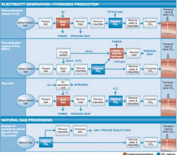
Carbon capture and storage (CCS) is a potential means of mitigating the contribu-tion of fossil fuel emissions (from power generacontribu-tion) to global warming [55,56] and ocean acidification [57]. Depending on the process or power plant application in question, there are three main approaches to capture the CO2 generated from a primary fossil fuel (coal,
natural gas or oil), biomass, or mixtures of these fuels:
Post-combustion systems separate CO2 from the flue gases produced by the
com-bustion of the primary fuel in air. It concerns mainly the separation of the small fraction of CO2 (typically 3-15% by volume) from the main constituent N2 (from air).
Pre-combustion systems process the primary fuel in a reactor with steam and air or oxygen to produce a mixture consisting mainly of carbon monoxide and hydrogen (“synthesis gas”). Additional hydrogen, together with CO2, is produced by reacting the
carbon monoxide with steam in a second reactor (a “shift reactor”). The resulting mix-ture of hydrogen and CO2 can then be separated into a CO2 gas stream, and a stream
of hydrogen. Although the initial fuel conversion steps are more elaborate and costly than in post-combustion systems, the high concentrations of CO2 produced by the shift
reactor (typically 15 to 60% by volume on a dry basis) and the high pressures often encountered in these applications are more favourable for CO2 separation.
Oxyfuel combustion systems use oxygen instead of air for combustion of the primary fuel to produce a flue gas that is mainly water vapour and CO2. This results in a flue
gas with high CO2 concentrations (greater than 80% by volume). Oxyfuel combustion
requires the upstream separation of oxygen from air, with a purity of 95-99% oxygen assumed in most current designs. Further treatment of the flue gas may be needed to remove air pollutants and noncondensed gases (such as nitrogen) from the flue gas before the CO2 is sent to storage. The oxyfuel combustion systems are still in the
demonstra-tion phase [58].
The schematic presentation of the above CO2capture processes are demonstrated in
Fig.1.11. Besides the above systems, CO2 capture is also used in large-scale production
of hydrogen (ammonia and fertilizer manufacture, petroleum refinery operations) and in natural gas sweetening (separation mainly from CH4). Generally speaking, the
separa-tion of CO2 from N2 , CO2 from CH4 , and CO2 from H2 are three distinct separation
challenges faced by the electrical energy, natural gas, and syngas production sectors, respectively.
1.3.2 Polymer membranes for CO2 capture
Membrane-based technology is under development aiming at advancing towards sustainable systems that minimize CO2 emissions. Three main approaches are mainly
under study (Fig. 1.12): (i) non-dispersive contact via a microporous membrane (mostly focused on postcombustion capture); (ii) gas permeation, mainly by using dense
mem-Figure 1.11: Schematic presentation of CO2capture in post-combustion, pre-combustion,
branes (mostly for pre-combustion capture); and (iii) supported liquid membranes (pre-combustion and post-(pre-combustion capture are both targets).
Figure 1.12: Schema of mass transfer in the systems: (a) non-dispersive contact via a microporous membrane (membrane contractor); (b) gas permeation through a dense membrane; (c) support liquid membrane [60]
Non-dispersive Contact via a Microporous Membrane
Non-dispersive absorption using a gas-liquid contactor presents interesting advan-tages compared to the conventional absorption towers and also, they may be strong com-petitors to the use of dense membranes and supported liquid membranes. It is mainly applied in post-combustion capture. Regarding the traditional absorption performed in scrubbers, the use of membrane-based absorption has more operational flexibility due to the independent control of gas and liquid flow rates, a controlled and known interfacial area, a linear scale-up thanks to the modularity of membrane contactors; it is compact and less energy consuming and does not suffer from dragging of drops of solvent since the gas and liquid phases are kept separated in the two compartments of the contactor (the shell and tube sides) and the mass transfer takes place through the membrane pores. The mass transfer of CO2 from the gas to the liquid phase does not have a significant
impact on the gas flow because of the low concentration of CO2 in the gas stream [61].
In addition, compared to other membrane systems, the membrane pores are filled (in theory) with gas and the mass transfer through the membrane should be favoured in
comparison to using dense membranes or membranes with pores filled by liquid (sup-ported liquid membranes). The membrane does not provide selectivity to the separation since its role is to act as a barrier and to increase the surface for mass transfer exchange between both phases but the morphology of the membrane has a non-negligible influence on the process performance [62]. The pore size and porosity of the membrane are key factors to consider since the contact between the gas and liquid phase occurs in the pores of the membrane and higher membrane porosity leads to a better performance [63–66]. However, the selection of the absorption liquid determines the selectivity of the separa-tion; also, it is critical to have good chemical compatibility between the solvent and the membrane contactor (i.e., membrane, potting material and housing) and the prevention of membrane wettability is essential to ensure a long-term application.
Faced to current challenges to develop this technology in an industrial scale, it can be stated that there are four main aspects to consider and solve [67, 68]: (i) wetting of the membrane, which increases the resistance to mass transfer and decreases the process efficiency dramatically (Favre et al. have prepared a membrane contractor with a dense layer to effectively prevent wetting [69]); (ii) limited long-term stability, mainly related to the chemical resistance of the membrane material (many solvents may react chemi-cally with the polymer) and to the effect of temperature on the membrane structure; (iii) volatility of the solvent, which is an issue of concern from an economic and environmen-tal point of view and promotes the use of non-volatile solvents such as ionic liquids; and (iv) presence of other compounds in the gas stream, acting as competitors and limiting the mass transfer of the target compound. All these considerations are strongly linked with the selection of the membrane-solvent system.
Gas Permeation
In gas permeation, the membrane is responsible for the separation since it deter-mines the permeability and selectivity of the process. Thus, no liquid is involved. This approach is mainly focused on pre-combustion capture (H2/CO2mixture) but also many
studies try to develop membranes for post-combustion separations (CO2/N2 mixture).
Although the upper bound of the Robeson plot has been revisited over the last years [70–72], contributing to the experimental and theoretical upper bounds for poly-meric membranes, the trade-off between the selectivity and the permeability is still the challenge to face in synthesis of membranes for gas permeation. The Robeson plot re-visited in 2008 is shown in Fig. 1.13 [71].
The driving force of gas separation membranes for CO2 permeation is the partial
pressure difference between the feed and the permeate side. Consequently, the major challenge that has to be faced for their implementation in the industry is the scale of the process due to the high volume of gas stream to be treated and the low concentration (i.e. low driving force) of CO2 (e.g. 3-15 vol.% CO2 in post-combustion processes),
leading to the requirement of large membrane areas to perform the separation. The use of hollow fibers is hence particularly interesting.
Figure 1.13: Robeson plot 2008 for CO2/N2 [71].
The plasticization effect has to be also considered in the development of polymeric membranes. High solubility of CO2 (and other compounds that can be present in the
gas stream such as H2S, SO2, NH3, water, etc) in the polymer may induce plasticization,
causing the polymer to swell with disruption of the polymer matrix, with an increase in the mobility of the polymer chains, thereby adversely changing the membrane perme-ation characteristics [73,74]. (see Section 1.3.3)
The effect of water in the gas stream has significant influence in the process per-formance. For example, Liu et al. studied the gas permeation through water-swollen hydrogel membranes. They found that the permeability of CO2 and N2 increased with
an increase in the water content in the membrane and tended to level off when the wa-ter content was sufficiently high (with gas permeability lower than the gas permeability in pure water). The corresponding CO2/N2 selectivity did not vary substantially with
water content. Reijerkerk et al. [73] observed that the presence of water vapour had a stronger influence on the N2 permeability in polyethylene oxide-based membranes and
the CO2/N2 selectivity increased with increasing water vapour activity. Since flue gas
contains water (usually in saturation levels), those systems can be used for the simulta-neous removal of CO2 and water.
Facilitated transport membranes (also in ionic liquid-based structures) have received a lot of attention in gas separation because they can improve significantly the permse-lectivity, making the membrane go far beyond the upper bound shown in Robeson’s plot. There are different approaches but the basis is the incorporation of a carrier agent into the membrane (linked structurally, immobilized into the pores or supported on the membrane), which reacts reversibly with the penetrating species [75]. The permeating species (e.g. CO2) diffuses across the membrane until released to the permeate side
and the presence of the carrier enhances significantly the selectivity towards the target compound and also, the permeability.
Supported Liquid Membranes
The development of supported liquid membranes (SLMs) has taken a great impulse in the last years thanks to the use of ionic liquids as solvent. The basis of this approach consists of a liquid supported on the surface of the membrane or introduced inside the pores of the membrane (in this last case, a more appropriate denomination would be immobilized liquid membranes).
The main technical challenge of SLMs is the stability of the membrane since the solvent in the pores can evaporate or be ‘washed out’ after long time of operation.
In addition, the driving force needed to perform the separation is the pressure diffe-rence between the feed and the permeate side, which means that the permeation of CO2
through the membrane will be enhanced when the feed gas is compressed [76] (since flue gases are normally at low pressures, such as 1 atm) or the permeate side works under vacuum conditions. However, the first situation increases the cost of the overall process and the second option promotes the instability of the membrane over time due to solvent volatilization.
In contrast, there is an important effect of the concentration of CO2 in the feed
stream. But it is important to distinguish the increase of CO2 partial pressure due to an
increase of the total pressure and due to an increase of the CO2 concentration since their
effects on the membrane performance are not the same. Gorji et al. observed that the CO2 capture performance through amine solution membranes decreases with increasing
CO2 partial pressure of the feed at constant total pressure [77]. This means that high
concentration of CO2penalizes the overall performance, although better separation may
be obtained for low concentration of CO2 in the gas stream in contrast with the use of
porous membranes and liquid flowing inside the contactor [78].
Membrane stability and solvent viscosity can be considered as the bottlenecks of this technology. An increase of the concentration of the reagent should involve a better CO2 removal since the selectivity and permeability are given by the interaction with
the solvent. However, when the viscosity of the solvent becomes high, CO2
diffusiv-ity through the SLM decreases. Using ionic liquids eliminates the problem of solvent evaporation that may occur in conventional SLMs, aiming at high stability. Their high CO2 solubility, selectivity of ionic liquids are also appreciable. However, viscosity and
pressure stability are pending issues [79,80].
The addition of carriers to the SILMs to promote the facilitated transport is being studied by several authors [81, 82]. Nevertheless, it was observed that there was not a large potential for an overall improvement of performances.
Also, as same as non-dispersive absorption and gas permeation, the effect of ope-rating conditions on the process efficiency is large enough to promote the study under real conditions.
1.3.3 CO2 plasticization and competitive sorption in polymer
mem-branes
Plasticization phenomenon
Gas separation through dense membranes is generally more effective using glassy polymers, which can differentiate gases based on their different diffusivities. Theoreti-cal models for the permeability coefficients of gases through glassy polymers distinguish between the behavior below and above the glass transition temperature [83]. Above the glass transition temperature, the permeability coefficient of a (rubbery) polymer is constant for low pressures and increases eventually at elevated feed pressures. Be-low the glass transition temperature, the plasticization effect is often observed when highly sorbing gas such as CO2 is fed at a large partial pressure. A typical effect of
plasticization is that the permeability versus pressure curves go through a minimum, as illustrated in Figure 1.14. Initially, there is a decrease in permeability as the pres-sure is increased, due to a faster decrease in solubility than an increase in diffusivity with increasing pressure [84]. At a certain point, the high sorbing gas concentration disrupts the chain packing, leading to an increase in free volume and an enhanced seg-mental mobility. At this point, the increase in diffusivity is stronger than the decrease in solubility, and thereby the permeability increases with pressure. The pressure cor-responding to the minimum permeability is called the plasticization pressure (Fig. 1.14).
Figure 1.14: Schematic presentation showing plasticization effects on membrane sepa-ration performance: plasticization causes an increase in permeability and decrease in selectivity as pressure of sorbed penetrant increases [85].
In membrane science and in particular in gas separation, the phenomenon of penetrant-induced plasticization is generally considered as an undesired, ‘negative’ feature since it represents losses in membrane performance [86–89]. The increase in local segmental motion of the polymer chains results in enhanced transport rates of all penetrants to be separated. Since the transport rate of a ‘slow’ penetrant is more affected than that of a ‘fast’ component, plasticization typically results in a loss of membrane selectivity when gas mixtures are fed to the membrane (Fig.1.14). Plasticization can be suppressed by various chemical means to mitigate or to prevent membrane selectivity loss. The most widely used methods include annealing, cross-linking and polymer blending. Thermal
annealing induces a densification of the polymer. Cross-linking increases chain packing and inhibits the intrasegmental and intersegmental mobilities. Polymer blends involves the blending of a polymer affected by the sorbed molecules with one that is hardly af-fected.
Competitive sorption in gas mixtures
Another factor that influences the mixed gas separation membrane performance is the competitive sorption: the presence of one gas species can affect the solubility of another gas species. Competitive sorption can affect both rubbery and glassy polymers to varying extents. For rubbery polymers, the effects can be described by Flory-Huggins theory. The competitive sorption of one gas can lead to an increase or to a decrease in the solubility of another. For glassy polymers, the permeabilities of penetrants are al-ways decreased due to the competition effects between penetrants on Langmuir sorption sites (which are associated with the non-equilibrium free volume in glassy polymers), according to the dual mode sorption model [90]. Different from plasticization, competi-tive sorption is related to intrinsic material properties and cannot be tailored.
Researches on plasticization behavior and competitive sorption of room tem-perature ionic liquids (RTILs) and poly(RTILs)
Concerning the plasticization and mixture gas competitive sorption in ionic liquids, several papers were published. F. Karadas et al. studied CO2 absorption on
1-butyl-3-methylimidazolium hexafluophosphate, 1-ethyl-3-1-butyl-3-methylimidazolium bis(trifluoromethyl-sulfonyl) imide, and 1-butyl-3-methylimidazolium bis(trifluoromethylbis(trifluoromethyl-sulfonyl) imide ionic liquids and observed a remarkable swelling effect upon CO2from pressures higher than 10
MPa, which led to an apparent decrease of the CO2 absorbed amount [91]. M. Wessling
and R. D. Noble reported the plasticization behavior of poly(ionic liquid) (synthesized from styrene-based imidazolium bis(trifluoromethane)sulfonamide RTIL monomers) at pressures above 10 bar (the gas mixure used was CO2/CH4) [92]. They discovered that
although poly(RTILs) are glassy in nature, poly(RTILs) do not show a minimum in permeation rates for CO2: the permeability increases continuously with increasing feed
pressure. Another distinctly different phenomenon of poly(RTILs) opposed to regular glassy polymers such as polyimides, polysulfones or polycarbonates is the full reversibility of the diffusional processes on the time scale. Those unique properties were attributed to the strong ionic interactions counter-balancing the volume dilation induced by the sorbed CO2 as poly(RTILs) with short side chains are less vulnerable than those with longer
side chains. Hert et al. discovered experimentally the competition sorption between CO2 and O2 (50/50 mol%) in 1-hexyl-3-methylimidazolium bis(trifluoromethylsulfonyl)
imide. The CO2solubility in the mixed gas system was less than the CO2solubility in the
pure gas system [93]. This is coherent with the CO2permeability decrease observed by Li
(which was attributed to the competitive sorption). According to them, CO2-induced
plasticization dominated the competitive sorption at 20 atm and the CO2 permeability
in the mixed gas became higher than pure CO2 permeability. Concerning thin polymer films
Another interesting point to mention is that the behavior of integrally thin-skinned (” < 0.5 µm) or thin dense (” < 3 µm) polymer films may be different from thick dense polymer films, as the physicochemical properties are different from polymer bulk pro-perties. One example is the thickness dependence of the glass transition temperature in thin polymer films. Forrest and Dalnoki-Veress [94] observed a Tg-reduction with
decreasing polymer film thickness (” < 0.3 µm), which was explained by polymer chain confinement [95]. In membrane gas separation experiments also evidence was found for difference in polymer properties between thick and thin polymer films. Jordan et al. [96] used CO2 as a conditioning agent to enhance the transport of O2and N2in thick
dense films and asymmetric hollow fibers and recognized that lower CO2 pressures were
needed to induce swelling effects for asymmetric hollow fibers than for thick dense films. They hypothesized that the dense skin of an asymmetric hollow fiber consists of layers of nodules that are interconnected by polymer chains. These loosely packed chains are susceptible to movement and structural change by the highly sorbing CO2. However,
Shishatskii et al. [97], who investigated the effect of film thickness on material density, showed that a decreasing thickness resulted in an increase of cohesive energy density (CED) and consequently a higher gas solubility and lower gas diffusivity for the thin material. This was verified by Dorkenoo and Pfromm [98], who characterized physical aging by gas permeation experiments in poly[1-(trimethylsilyl)-1-propyne] films. The activation energies for permeation were often significantly higher for thin-skinned mem-branes, implying higher cohesive energy densities (CED), due to a lower free volume in comparison to the bulk polymer. Besides that, Pfromm et al. [99] observed an increased permselectivity for O2 and N2 in asymmetric PSF films compared to the isotropic
pro-perties due to increased activation energies for permeation. Besides physical ageing and other physicochemical properties, also plasticization behavior is thickness dependent, as observed by Wessling et al. [100]. They showed that the CO2 permeability in
compo-site membranes, consisting of PI top layers (thickness between 1.5 and 4 µm) and a PDMS (polydimethylsiloxane) support film continuously increased with feed pressure, and became more pronounced with decreasing polyimide (PI) layer thickness. It was hy-pothesized by Pfromm and Koros [98] that, due to elimination of Langmuir sorption sites as a consequence of accelerated aging (the polymer may be locally more ordered due to aging), there is less CO2 needed to induce plasticization. On the other hand, Shishatskii
et al. [97] reported an increasing solubility with increasing density (as a consequence of decreasing film thickness). They suggested that this was due to increases in the CED. The inverted pressure dependence on CO2 permeability was also found by Pfromm et
al. [99] in an asymmetric poly(ester carbonate) film. A combination of factors would explain the unusual shape of this curve, such as a different distribution of free volume,
a different orientation of the polymer molecules in the skin layer, a lower free volume in the skin layer and a smaller number/size of hypothetical Langmuir sites.
Researchers also found that plasticization may also be suppressed in skin layered polymers by using a gas mixture (besides the conventional chemical methods). Kapan-taidakis [101] and Barsema [102] found that plasticization of integrally skinned asym-metric hollow fibers of polyethersulfone/polyimide (Matrimid 5218) and P84 (co-PI, Lenzing) seems to be suppressed when CO2/N2 mixtures of 55/45 and 80/20 wt.% are
used. The CO2 and N2 permeability decreased slightly as a function of the CO2 partial
pressure over the whole pressure range 1-20 bar studied, both in the same order, leading to a constant separation factor. This observed phenomenon was hypothesized to be based on competitive sorption. The same explanation was given by Vu et al. [103] for the observed depression of the CO2 permeance as a function of pressure 7-55 bar using
Matrimid polyimide hollow fibers in a 10% CO2/90% CH4gas mixture. Their CO2/CH4
separation factor kept nearly constant up to 40 bar. Yoshino et al. [104] performed gas separation experiments in integrally skinned asymmetric hollow fibers with 50/50 mol% binary mixtures of C3H6/C3H8 and C4H6 /C4H10 and observed no plasticization effects
for the first mixture, but strong plasticization effects for the second (pressure range, 1-5 bar). Wessling et al. found that when an inert gas (N2 or CH4) was introduced
to a binary gas mixture of CO2 plasticization was suppressed. Based on the mixed gas
permeation model they consider that there exists a subtle balance between competi-tive sorption and plasticization, which means that plasticization effects such as polymer network dilation are masked during mixed gas experiments [105]. On the other hand, Wang et al. [106] investigated the true separation performance of 6FDA-based polyimide hollow fiber membranes in a binary (40/60 mol%) gas mixture of CO2 and CH4 and did
observe plasticization effects. They hypothesized that plasticization, which increased the permeability, offsets the combined effects of competitive sorption and non-ideal gas behavior (especially in a gas mixture), which normally both decrease the permeability. However, their gas permeation results were reported at one partial CO2 pressure, 13.9
bar and were compared to pure gas permeation results at the accompanying partial pres-sure, 5.5 bar.
1.4 Process intensification
The birth of process intensification as a chemical engineering discipline was marked by the paper published in 1983 by Colin Ramshaw, describing process intensification as “devising an exceedingly compact plant which reduces both the ‘main plant item’ and the installation’s costs” [107]. While according to Heggs, process intensification is con-cerned with order-of-magnitude reductions in process plant and equipment [108]. In one of his subsequent papers, Ramshaw writes about typical equipment volume reduction by two or three orders of magnitude [109].
The philosophy of process intensification has been traditionally characterized by four words: smaller, cheaper, safer, slicker [110]. And indeed, equipment size, land use
costs, and process safety are among the most important process intensification incentives. But the motivation for developing and applying process intensifying equipment and me-thods is finally not only given by the prospect of dramatic cost reductions, but also by increasing the sustainability of chemical production [111]. Today, process intensification represent one of the most promising strategies believed to bring drastic improvements in manufacturing and processing, substantially decreasing equipment-size/production-capacity ratio, reducing raw materials, saving energy input, replacing and reducing ha-zardous waste, recycling waste materials (Fig. 1.15).
Figure 1.15: Main benefits from process intensification [110]. In general, the process intensification can be classified as following:
- Novel reactors as well as intensive mixing, heat-transfer and mass- transfer devices (static mixers, monolithic catalysts, microreactors, rotating devices);
- Integration of reaction and one or more unit operations (separation, heat exchange, or phase transition) into so-called multifunctional reactors (reverse-flow reactor, reactive distillation, membrane reactors, reactive extrusion, fuel cells);
- Development of new or hybrid separations (membrane absorption and stripping, membrane distillation, adsorptive distillation);
- Use of alternative forms and sources of energy for processing (centrifugal fields, ultrasound, solar energy, microwaves, electric fields, gliding arc);
- New process-control methods (like intentional unsteady-state operation).
The reactor concept investigated in the work at hand is a flow-through catalytic membrane reactor. It can be regarded a part of the process intensification family, closely related to microreactors due its small characteristic dimensions. Hereinafter, concepts on both microreactors and catalytic membranes are briefly introduced as the similari-ties and differences between them help to better understand the concept and potential benefits of the flow-through membrane reactor.

![Figure 1.27: Some cations and anions constituting room temperature ionic liquids (RTILs) [248]](https://thumb-eu.123doks.com/thumbv2/123doknet/2087212.7289/51.892.171.680.525.711/figure-cations-anions-constituting-temperature-ionic-liquids-rtils.webp)