UNIVERSITE DE SHERBROOKE Faculte de genie
Departement de genie Mecanique
Caracterisation du transport fluidique et thermique dans
les mousses metalliques capillaires en cuivre
Characterization o f fluid and thermal transport in copper
metal foam wicks
These de doctorat Specialite: genie mecanique
Mahmood Reza Salim Shirazy Jury: Luc. G. Frechette (directeur)
Marcel Lacroix Raymond Panneton Yoav Peles
1+1
Library and Archives Canada Published Heritage Branch Bibliotheque et Archives Canada Direction du Patrimoine de I'edition 395 Wellington Street Ottawa ON K 1A0N 4 Canada 395, rue Wellington Ottawa ON K1A 0N4 CanadaYour file Votre reference ISBN: 978-0-499-00424-6 Our file Notre reference ISBN: 978-0-499-00424-6
N O TICE:
T he auth or has granted a non
exclusive license allow ing Library and A rch ive s C anada to reproduce, publish, archive, preserve, conserve, com m u n icate to the public by
te le co m m un ica tion or on the Internet, loan, distrbute and sell theses
w orldw ide, fo r com m ercial o r non com m ercial purposes, in m icroform , paper, e le ctron ic a n d /o r any o ther form ats.
AVIS:
L 'auteur a accorde une licence non exclusive perm e tta nt a la B ibliotheque et A rch ive s C anada de reproduire, publier, archiver, sauvegarder, conserver, tra nsm ettre au public par te le co m m un ica tion ou par I'lnternet, preter, d istrib ue r e t vendre des the se s partout dans le m onde, a des fins co m m e rcia le s ou autres, sur su pp o rt m icroform e, papier, e lectronique et/ou autres form ats.
T he auth or retains copyright o w nership and m oral rights in this thesis. N either the thesis nor substantial extracts from it m ay be printed or o therw ise reproduced w ith o u t the author's perm ission.
L'auteur conserve la propriete du dro it d 'a ute ur et des droits m o ra u x qui protege cette these. Ni la these ni des e xtraits su bsta ntie ls de celle-ci ne d oiven t etre im prim es ou autre m e n t
reproduits sans son autorisation.
In com pliance w ith the C anadian P rivacy A c t som e supporting form s m ay have been rem oved from this thesis.
W hile these form s m ay be included in the d o cu m e n t page count, the ir rem oval does not re p re sen t any loss o f co nte nt from the thesis.
C o n fo rm em e n t a la loi canadienne sur la protection de la vie privee, quelques
form u la ire s secon d aires ont ete enleves de cette these.
Bien que ces form u la ire s a ient inclus dans la pagination, il n'y aura aucun contenu m anquant.
A ma fam ille et mon adorable epouse,
RESUME
La gestion thermique de l'electronique constitue un defi majeur dans la fabrication et la production de circuits electroniques de haute performance. La hausse constante de la puissance de calcul necessite toujours plus d'energie, qui doit ensuite etre evacuee (sous forme de chaleur) de l'ordinateur. Parmi les diverses solutions, les caloducs sont proposes comme un moyen de transferer et finalement eliminer ce surplus de chaleur. La partie principale d’un caloduc typique est la meche qui foumit un milieu pour la capillarite et l'evaporation a l'interface liquide-vapeur. Differents materiaux sont proposes comme meche pour un caloduc et parmi eux, les mousses metalliques recemment inventees (Metafoam) presentent une performance tres significative et des limites de transport elevees par rapport aux materiaux concurrents. Par une approche essentiellement experimentale, les proprietes capillaires, de mouillage et d'evaporation des mousses metalliques en cuivre avec des porosites differentes ont ete etudiees. Une etude approfondie de caracterisation de surface est effectuee sur les mousses afin d'identifier le role de la mouillabilite de la surface sur la performance capillaire. On a demontre pour la premiere fois que la perte d’hydrophilicite des materiaux poreux en cuivre expose a l'air est provoquee par l'adsorption de composes organiques volatils et non par l'oxydation du cuivre. II est egalement deduit que la raison pour la haute limite de transport des mousses par rapport a d'autres materiaux est leur micro structure unique qui a deux niveaux de porosite. Cette micro structure bi-poreuse foumit des chemins pour le transport de liquide avec de faibles pertes de charge tandis que les plus petits pores favorisent l'evaporation par couches minces et produit une haute pression capillaire. La permeabilite et le rayon effectif des pores, deux parametres cles qui definissent la capacite de pompage, sont mesures experimentalement par le taux de montee de liquide. II est constate que le taux d'evaporation dans un materiau poreux est plus faible pendant la montee du liquide par rapport au meme materiau mais completement sature de liquide (regime stationnaire). Cela permettra d’ignorer l'evaporation naturelle dans cette methode et d’utiliser des modeles simplifies pour mesurer le rayon effectif des pores et la permeabilite. Le role de la recession du menisque dans le pompage capillaire et dans le taux d'evaporation est caracterise pour la premiere fois et un modele est propose pour mesurer le rayon de pore effectif de materiaux poreux dans des conditions d'operation. II est montre que le rayon de pore effectif peut diminuer jusqu'a 50% a cause de l'evaporation forcee. D ’une perspective plus generate, les differentes experiences ont demontre qu'il existe un couplage entre la capillarite et l'evaporation. Ce couplage est etabli par la variation de forme du menisque qui affecte a la fois la capillarite et l'evaporation. Cette these contribue done a faire la lumiere sur la capillarite, l'evaporation et leur interdependance dans les meches capillaires pour les appareils biphasiques de gestion thermique.
ABSTRACT
Thermal management o f electronics has become a major challenge in manufacturing and production o f high performance electronic chips. Constant rise o f computation power requires higher amount o f energy and subsequently this energy (in the form o f heat) should be transferred out o f the computer. Among other solutions, heat pipes are proposed as a means to transfer and eventually remove this excess heat. The main part o f a typical heat pipe is the wick which provides a medium for transport o f capillary driven flow and evaporation at the vapor-liquid interface. Different materials are proposed as wick for a heat pipe and among them, recently invented Bi-porous metal foams exhibit a very significant performance improve, i.e. high transport limit in comparison with competing materials. By a mainly experimental approach, capillary, wetting and evaporation properties o f copper metal foams with different porosities have been investigated. An in depth surface characterization study is done on the foams to identify the role o f surface wettability on the capillary performance. It is found for the first time that the hydrophilicity loss o f the copper based porous materials when exposed to air is caused by the adsorption o f volatile organic compounds and not by copper oxidation. It is also inferred that the reason for high transport limit o f the foams compared with other materials is their unique microstructure which has two levels o f porosity. This biporous microstructure provides paths for liquid transport with low pressure drop while the smaller pores provide for thin film evaporation and produce high capillary pressure. Permeability and effective pore radius, as two key parameters defining the pumping capacity, are measured experimentally by the rate o f rise method. It is also found that the evaporation rate o f a rising liquid in a porous material is lower compared with that o f the same material while saturated with stationary liquid. This will allow ignoring natural evaporation in the rate o f rise method and using simplified models to capture permeability and effective pore radius. The role o f meniscus recession in capillary pumping and evaporation rate is characterized for the first time and a model is proposed to measure the effective pore radius o f porous materials in operating conditions. It is shown that the effective pore radius can decrease up to 50% due to forced evaporation. In a more general perspective, through different experiments, it is shown that there is a coupling between capillarity and evaporation. This coupling is established through variation in meniscus shape which will affect both capillarity and evaporation. The findings o f this thesis will shed light on the capillarity, evaporation and their interconnected nature in the capillary wicks in two phase thermal management devices.
ACKNOWLEDEGMENTS
I am not sure how many students have the chance and opportunity in their graduate studies to work with people so influential that can profoundly change their attitude and understanding o f the whole life. Fortunately I was one o f them and I really wish more students have this opportunity like me! The most influential person throughout this life changing journey is my supervisor Professor Luc, G. Frechette. I would like to extend my gratitude to him, for teaching me not only the scientific concepts and the true meaning o f research but also for his human, ethical, patient and flexible attitude towards me. In my case, these qualities could mean the success or failure o f my PhD. Luc acted as a true mentor and friend during my PhD and working with him was certainly a turning point in my life. I would also like to thank the committee members, Professors Marcel Lacroix, Raymond Panneton and Yoav Peles for their valuable inputs and support regarding this research.
This work could not have been completed without the help, guidance and support o f Dominic Pilon, founder o f Metafoam Technologies Inc. Sebastien Labbe and others in Metafoam Technologies fabricated and provided the copper metal foam samples, whom I would like to thank. I would like to thank Professor Hugues Menard for insightful discussions on the surface chemistry o f the foams. I am also grateful to Sonia Blais, Irene Kelsey and Stephane Gutierrez o f the centre de caracterisation des materiaux (CCM) for their invaluable help in the characterization o f the foam samples. Sonia Fortin at the department o f mechanical engineering helped much by ordering and buying the many pieces required for different test setups used in this project. The help o f Sebastien Rioux, Claude Dugual and Real Dubuc in the fabrication o f the different components o f the test setups is highly appreciated. I would also like to thank Alexandre Landry- Blais and Louis-Simon Malo who during their internship in the Micros research group contributed to different activities related to this project.
My sincerest thanks go to all my past and present lab mates and friends, especially Selin, Mokhtar and Etienne. And last but not least, I wish to thank my parents, my brothers, and my wife Sanaz for their unconditional love and support during this journey.
TABLE OF CONTENTS
RESUME... ii ABSTRACT...iii ACKNOWLEDEGMENTS...iv LIST OF FIGURES... x LIST OF TABLES...xiii 1 Introduction...11.1 Need for thermal management...1
1.2 Heat pipes... 2
1.3 Copper metal foam wicks... 3
1.4 Thesis outline...5
2 State o f art...7
2.1 Heat pipe transport lim its... 7
2.1.1 Capillary and wetting properties of wicks... 10
2.2 Heat pipe thermal resistance...13
2.3 Project definition...15
2.4 Objectives o f the th esis...15
2.4.1 Capillary action...15
2.4.2 Evaporation... 16
2.5 Original contribution... 16
chapitre 3 Avant-Propos...18
3.1 A bstract... 20
3.2 Introduction... 20
3.3 Nomenclature...23
3.4 Operating limit correlations...25
3.4.1 Capillary lim it... 25
3.4.2 Boiling limit...27
3.4.3 Sonic lim it... 27
3.4.4 Entrainment lim it...28
3.4.5 Viscous limit... 28
3.5 Transport limits for a circular heat pipe...29
3.5.1 Results for different wick types... 29
3.5.2 Results for the Capillary limit... 31
3.5.3 Results for the boiling lim it...32
3.6 Parametric study o f capillary limit in a flat heat pipe... 33
3.6.1 Mathematical model...33
3.6.2 Heat pipe and wick dimensions... 37
3.6.3 Results o f the parametric study o f the capillary lim it... 38
3.7 A non-dimensional parameter for capillary lim it... 40
3.8 Design metrics for FH P... 42
3.9 Discussion and Conclusion... 42
3.10 Acknowledgments... 44
4 Mechanism o f wettability transition in copper metal foams: from superhydrophilic to hydrophobic... ;... 47 4.1 A bstract... 47 4.2 Introduction...47 4.3 Experimental M ethods... 51 4.3.1 Sample preparation... 51
4.3.2 Reduction process by hydrogen...52
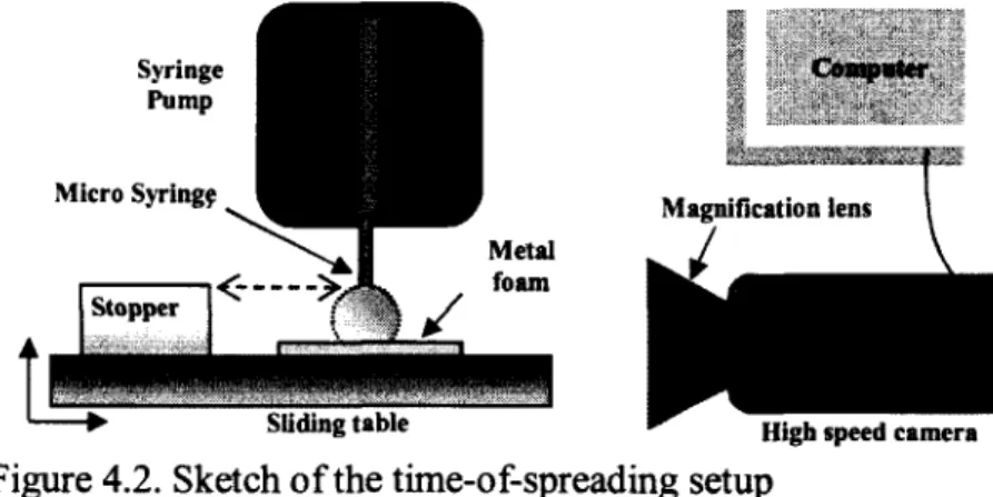
4.3.3 Time-of-spreading test setup... 53
4.3.4 Characterization techniques... 55
4.4 Hydrophobicity mechanism...55
4.5 Experimental R esults...58
4.5.1 Effect o f ambient atmosphere on the time-of-spreading... 58
4.5.2 X P S ... 60
4.5.3 TOF-SIMS...64
4.6 Discussion on wettability o f the foams and the carbon content...66
4.6.1 Effect o f an organic compound, a-Pinene... 67
4.7 Conclusions... 68
4.8 Acknowledgments... 69
chapitre 5 Avant-Propos... 70
5 Capillary and Wetting Properties o f Copper Metal Foams in the Presence o f Evaporation and Sintered Walls... 72
5.1 A bstract...72
5.2 Nomenclature...73
5.4 Governing equations and models... 78
5.5 Materials and m ethods... 80
5.5.1 Corrections on the raw data...85
5.6 Result and discussions...86
5.6.1 Rate o f rise experimental results...86
5.6.2 Evaporation effect... 89
5.7 Data analysis and parameter extraction... 93
5.7.1 Permeability and effective pore radius... 93
5.7.2 Internal contact angle... 96
5.8 Conclusion... 97
5.9 Acknowledgments... 99
chapitre 6 Avant-Propos... 100
6 Effect o f meniscus recession on the effective pore radius and capillary pumping o f copper metal foams...102
6.1 A bstract...102
6.2 Nomenclature... 102
6.3 Introduction... 104
6.4 Governing equations and models... 107
6.5 Experimental methods... 107
6.5.1 Sample properties... 107
6.5.2 Experimental setup... 109
6.5.3 Test procedure...I l l 6.6 Data reduction and parameter extraction...112
6.6.1 Mass measurements...112
6.6.2 Heat loss measurements... 113
6.7 Results and discussion... 115
6.7.1 Heat loss... 115
6.7.2 Wick Temperature... •... 116
6.7.3 Evaporation rate... 117
6.7.4 Effect o f temperature on the effective pore radius... 118
6.7.5 Conclusion... 121
6.8 Acknowledgements... 121
7 conclusions and future w ork...i... 122
7.1 Conclusions... 122
7.2 Suggested future work... 124
7.3 Conclusions (en fran?ais)... 126
7.4 Travaux futurs... 128
Appendix A ...130
A.l Solving the differential Eqautuins in chapter 3 ...130
Appendix B ...132
B.l Effect o f meniscus recession on wick thermal resistance... 132
LIST OF FIGURES
Figure 1.1 schematic drawing o f an operating heat pipe... 2
Figure 1.2 Metafoam copper foam wicks for heat pipe and vapor chambers[58]...3
Figure 1.3 Different microstructures o f (a) steel alloy metal foam [93] (b) copper metal foam [94] (c) sintered copper powder [76] (d) Metafoam copper metal foam s... 4
Figure 2.1 Simplified heat pipe thermal resistance network (only the lower half o f the heat pipe is depicted here)... 13
Figure 2.2 Schematic drawing o f liquid saturated wick and its associated thermal resistance 14 Figure 3.1 Different limits for sintered copper pow der...30
Figure 3.2 Different limits for 250 PPI copper foam... 30
Figure 3.3 Different limits for 60 PPI copper foam... 30
Figure 3.4 Different limits for 50 PPI copper foam...30
Figure 3.5 Capillary limit for different wicking materials ... 32
Figure 3.6 effect o f the different values o f nucleation radius r„ on the boiling limit for the 50 PPI foam...'...32
Figure 3.7 Vapor core modeling and its corresponding control volumes...34
Figure 3.8 Effect o f FHP length on the capillary lim it... 39
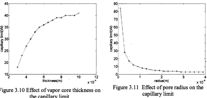
Figure 3.9 Effect o f permeability on the capillary limit... 39
Figure 3.10 Effect of vapor core thickness on the capillary limit...40
Figure 3.11 Effect o f pore radius on the capillary lim it...40
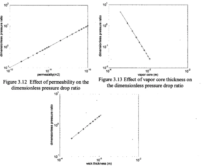
Figure 3.12 Effect o f permeability on the dimensionless pressure drop ratio...41
Figure 3.13 Effect o f vapor core thickness on the dimensionless pressure drop ratio...41
Figure 4.1. Morphology o f the 75 PPI copper metal foams: (a) optical image o f the copper foam surface (b) low magnification SEM (x70) o f the foam structure...52 Figure 4.2. Sketch o f the time-of-spreading setup... 53 Figure 4.3. Different steps o f spreading a water droplet on the surface o f a hydrophilic copper foam in 0.025 s...54 Figure 4.4. Effect o f the hydrogen reduction process on the copper metal foam sample exposed to air and before hydrogen reduction...58 Figure 4.5. Variation o f the time-of-spreading for the copper metal foams in (a) ambient air, showing hydrophobic transition; (b) nitrogen and extra dry pure air that remains hydrophilic.... 60 Figure 4.6. Typical XPS survey spectrum o f the copper metal foam surface (sample 3) after hydrogen reduction (Oh)... 61 Figure 4.7. XPS C 1 s spectra for copper metal foam showing the increase in carbon content with aging time... 62 Figure 4.8. Dependence o f (a) XPS Cu 2p and (b) Auger Cu L3M4.5M4 .5 spectra on time for
copper metal foam... 63 Figure 4.9. Time variation o f the XPS O Is spectra for copper metal foam...64 Figure 4.10. Positive ion TOF-SIMS spectra (left) and negative TOF-SIMS spectra (right) for two identical samples... 65 Figure 4.11. Percentage o f surface atomic concentration o f total carbon content (C Is) and other carbon species with the water time-of-spreading for a copper metal foam left in room ambient air over tim e... 67 Figure 5.1. Morphology o f the 75% porosity copper metal foams... 81 Figure 5.2. Different configurations o f the experimental setup to measure the rate o f rise o f a liquid based on mass... ;... 84 Figure 5.3. Measured raw data correction due to side meniscus, evaporation from container during the tests, and initial evaporation from the container before beginning the test... 86 Figure 5.4. Rate o f rise results for 68%, 75% and 82% porosity foams with acetone... 88 Figure 5.5. Non-dimensional evaporated mass measurement o f acetone for a 75% porosity foam in open and closed environments with one sintered wall (backed) and two sintered w alls 90
Figure 5.6. Rate o f rise results for the two setup configurations: stored mass setup (configuration I), total wicked mass setup (configuration II)... 92 Figure 5.7. Mass uptake values for different foam porosities in a closed container with acetone, ethanol and water... 96 Figure 6.1. Morphology o f the 75% porosity copper metal foams... 108 Figure 6.2 Schematic drawing o f a) the heater block and thermocouple locations (dimensions in mm) b) measurement setup with IR camera... 111 Figure 6.3 Comparison o f input power and individual contribution o f each heat transfer mode to the measured heat flow o f 68% porosity foam ...116 Figure 6.4 Axial temperature distribution in metal foams o f a) 68% porosity b) 75% porosity and c) 82% porosity, x = 0 is in the liquid container... 117 Figure 6.5 Effect o f (a) wall temperature and (b) heat flux on the evaporation rates o f the different foam porosities... 118 Figure 6.6 IR profile o f the 75% porosity foam (a) the whole surface is wet (wetted length, x = 35 mm) (b) liquid front decreased to x = 23 mm from liquid surface (c) liquid front in x = 13 mm from liquid surface... 119 Figure 6.7 (a)Values o f calculated effective pore radius for different heat fluxes (b) Values o f K/reff for different heat fluxes...120 Figure A.1 Steady-state thermal performance results for different foam porosities: (a) evaporation curves; (b) calculated wick thermal resistances as a function o f heat flux...133 Figure A.2 Variation o f effective pore radius and wick thermal resistance with input heat flux for different foam porosities...134
LIST OF TABLES
Table 3.1 . Dimensions o f the circular heat p ip e... 29
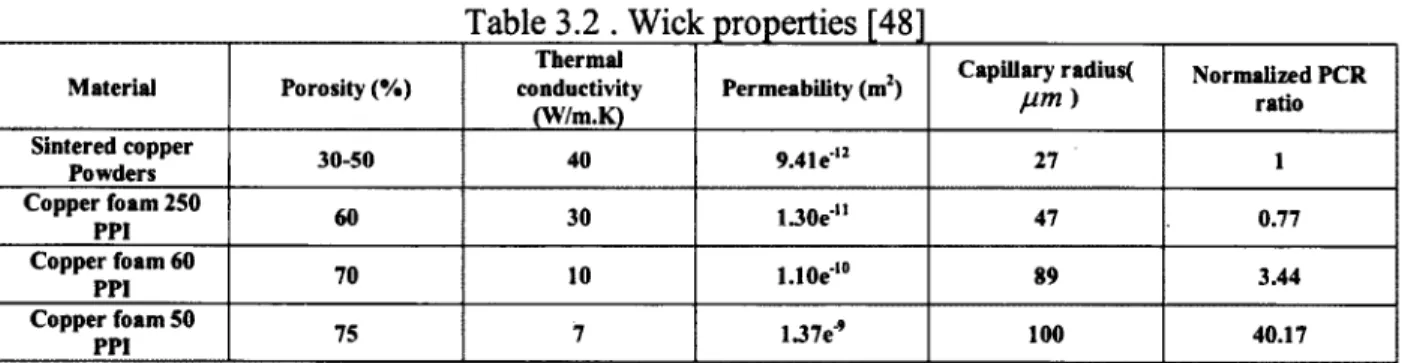
Table 3.2 . Wick properties [48]... 29
Table 3.3. Dimensions and properties o f the nominal F H P ... 38
Table 4.1. Percent (%) surface Atomic concentration... 64
Table 4.2. Positive ions with the most significant increase after 3 hours exposure to room ambient air (peak intensities normalized with respect to the copper at 100%)... 65
Table 4.3. Negative ions with the most significant increase after 3 hours exposure to room ambient air (peak intensities normalized with respect to the copper at 100%)... 66
Table 5.1. Mass uptake rate for four limiting cases... 80
Table 5.2. Properties o f the liquids used in the experiments, 20 °C [2]... 82
Table 5.3. Measured evaporation flux for bare samples, m (kg/m2 s)... 91
Table 5.4. Permeability K and effective pore radius reff for foam samples o f 68%, 75% and 82% porosities...94
Table 5.5. Values o f K/reff (pm) for different conditions and configurations... 95
Table 5.6. Internal contact angle o f water in an open ambient... 97
Table 6.1 Properties o f the ethanol, 20 °C [2 ]...109
Table 6.2 Onset o f dryout for different foam porosities... 116
Table 6.3. Permeability K and effective pore radius reff for foam samples o f 68%, 75% and 82% porosities measured by the rate o f rise method (no applied heat flux) [72]...121
1 INTRODUCTION
1.1 Need for thermal management
Since the first days o f invention o f the computing machines in the 1940s, extracting and taking out the excess heat has been an important issue [13]. The invention o f transistors, integrated circuits (IC) and complentry metal-oxide semiconductor (CMOS) circuit technology to replace high heat dissipating bipolar circuit technology have not been able to satisfy the need for thermal management. Two main factors leading to ever increasing rate o f heat dissipation are denser packaging and higher performance circuits, which are required steadily by the market. In 2005, the size o f the market o f cooling technologies for thermal management o f PC’s and telecom equipment was estimated to be $4.1 billion per year with the prospect o f $4.8 billion [3]. At present, the heat fluxes in high end server applications are around 100W/cm2 (around 10 times that o f a household clothes iron[50]) and it is predicted to increase up to 500-1000W/cm2 (near the ballistic re-entry heat flux o f 1000W/cm2) for the next generation o f chips and electronic devices [38]. Currently the next objective for cooling technologies research is 300W/cm2 [3]. Traditionally, air cooling using extended heat sinks (fins) and fans has been the main cooling method for electronics, but this technology is at its limits and cannot satisfy the increasing rate o f dissipated heat in new chips [91]. Different technologies have been proposed to address the need for an effective cooling technology. Jet impingement, Spray cooling, single and two phase flow in micro-channels, micro-pumps, miniature flat heat pipes, transient phase change energy storage systems, thermoelectric coolers and piezoelectric fans have been studies and compared in some review papers[3, 25, 38, 85]. Among them, jet impingement [38] and boiling in micro-channels [3] have demonstrated the highest performance. However, they both face important challenges before being employed in commercial systems and currently much research is being done to better understand their physics. But as a short and medium term solution, heat pipes seem very appealing.
1.2 Heat pipes
Heat pipes are passive micro-fluidic devices that are usually designed for the thermal management o f electronic components [44]. They have also been used in other applications such as the cooling o f fuel cells. A heat pipe is a cavity o f small thickness filled with a two-phase working fluid (Figure 1.1). A heat input source is located at one end and a heat sink is placed at the other end o f the cavity with the other parts being insulated. Evaporation and condensation occur at the location o f the heat source and the heat sink, respectively. The liquid returns from the condenser to the evaporator by capillary action through a porous wick structure made o f meshes, sintered powder wicks or metal foams (the focus o f this thesis). The vapor travels back to the condenser through the vapor core. Since the latent heat o f vaporization is high, heat pipes are able to transfer high heat fluxes with small temperature gradients. Therefore, the overall thermal resistance o f the device is significantly lower than a solid material o f the same dimensions.
Porous wick material
C ondensation
Evaporation
Vapor core
Heat input Heat rejection
Figure 1.1 schematic drawing o f an operating heat pipe
Heat pipe and heat spreaders (vapor chambers) have the same operating principle and the only difference is the location o f evaporator and condenser. In heat pipes, evaporator and condenser zones are located at the extremities o f the device and the objective is to transport heat with
minimum temperature drop through a relatively long distance. In heat spreaders, heat is transported from a small high density heat source to a large area heat sink. The heat transport distance in vapor chambers is smaller compared with heat pipes but occurs in two dimensions.
1.3 Copper metal foam wicks
The heat pipe design and type o f wicking material are the main factors that influence the heat transfer capability o f a heat pipe [79]. Open cell metal foams are proposed as wicks in heat pipes. Metal foams are a good candidate for two phase and single phase chip cooling because they are thermally conductive, light weight, have a high surface area and high porosity, and can provide good thermal contact between the heat pipe wall and the wick. Novel open cell metallic foams can be fabricated with a wide range o f porosities, material composition, and micro structures, through a patented process initially developed at the National Research Council, NRC-IMI (Bourcherville, Qc, Canada) and now being manufactured and commercialized by the Canadian company Metafoam Technologies (Figure 1.2). In preliminary tests, these foams exhibit higher operating limits in a heat pipe than common wicks, suggesting high cooling rates for microelectronics applications [57].
Figure 1.2 Metafoam copper foam wicks for heat pipe and vapor chambers[58]
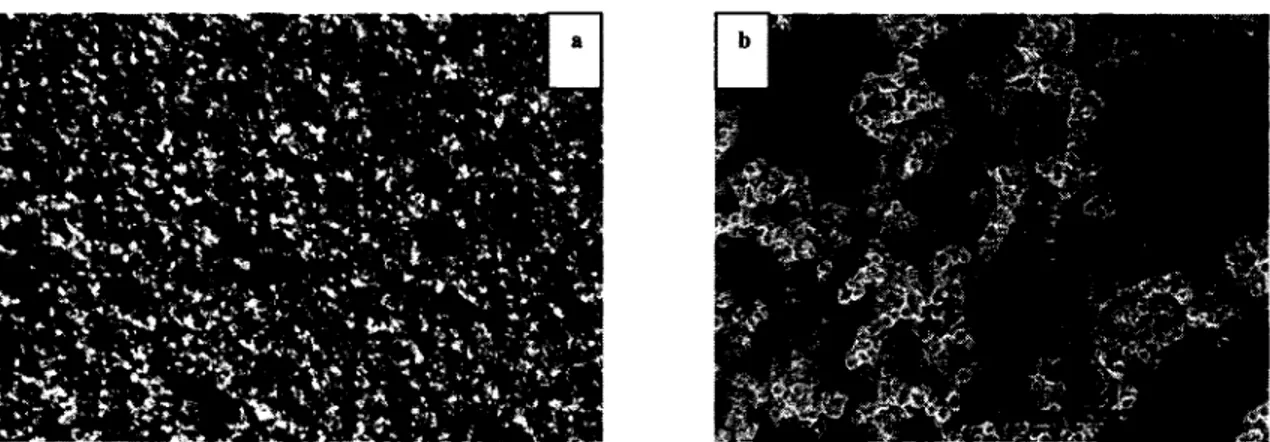
The novel aspect o f Metafoam copper foams is their particular micro structure compared with other metal foams and sintered copper powder (Figure 1.3). As it can be seen in Figure 1.3d, the foams have a spherical cluster structure (SCS) with the approximate diameter o f 10-50pm and unlike other types o f metal foams (Figure 1.3a and b), no ligaments as well as no polygon shape cells can be observed. Distinct pores are hard to find and several through holes are observed.
Instead, the small particles join each other to form clusters that are separated from each other to provide a large-scale porosity in the foam (Figure 1.3d). Within the clusters, we can observe a second smaller scale porosity formed between the particles. The micro structure formed by the small particles and their clusters is therefore characterized by two pore scales and a high surface area. This is very different than other porous wicks which are characterized by having only one level o f porosity. This biporous microstructure may lead to interesting capillary and evaporation properties that has not yet been fully characterized.
Figure 1.3 Different microstructures o f (a) steel alloy metal foam [93] (b) copper metal foam [94] (c) sintered copper powder [76] (d) Metafoam copper metal foams
This project is therefore aimed at studying the mechanism o f capillary driven heat and mass transfer for heat pipes employing these novel copper metal foams as wicks. The general objective in this research will be to understand the mechanism o f capillarity and evaporation in wicks made o f Metafoam materials and characterize the corresponding parameters. In a more general perspective, through different experiments, it will be shown that there is an interconnection between capillarity and evaporation. This interconnection is established through variations in the meniscus shape which will affect both capillarity and evaporation. This will be discussed in more detail in the future sections.
1.4 Thesis outline
This thesis includes 7 chapters. State o f art is presented in chapter 2, which also includes the overall scientific notions required to understand the subsequent chapters. The project definition and objectives are also discussed in this chapter. Chapter 3 covers the results o f a parametric study on the heat pipe transport limits, showing that capillary limit is the dominant limit in the performance o f heat pipes using metal foams. Therefore, capillarity and evaporation as well as wettability are identified as the main transport mechanisms involved in this limit and studied in more detail in the subsequent chapters. Wettability mechanism in copper metal foams is studied in chapter 4 and a wetting and surface characterization study is presented. The reason for hydrophilicity loss o f copper metal foams is explained for the first time and the double scale porosity o f the foams is shown through microscopic observations. As the next step, Capillary properties o f different porosity copper foams are investigated in chapter 5. The effect o f evaporation on capillarity is also investigated in this chapter. Evaporation rate is varied by using partially saturated ambient and attaching external walls. Effect o f natural evaporation on the rate o f capillary liquid rise is evaluated and it is shown that evaporation rate from a capillary driven rising liquid in a porous media is less than that o f a saturated sample. This shows a clear effect o f capillarity on the evaporation occurring in a porous material. The interconnection between capillarity and evaporation can best be seen in chapter 6 and appendix 1. Chapter 6 presents the experimental setup to study the evaporation properties o f foams. In this chapter, the meniscus recession effect due to forced evaporation on the capillary pumping is investigated. It will be seen
that higher evaporation rate will lead to meniscus recession which in turn will increase capillary pumping rate. The impact o f meniscus recession on the wick thermal resistance is also evaluated and studied in appendix 1. Lastly, chapter 7 provides conclusions and suggestions for future work.
2 STATE OF ART
From the practical point o f view and in order to choose a heat pipe or heat spreader for electronics thermal management, the device’s performance should be evaluated by suitable metrics. These metrics are high heat and mass transport limits and low overall thermal resistance. The former deals mostly with capillarity whereas the latter includes mainly evaporation. These two metrics and their underlying phenomena (capillarity and evaporation) will be discussed in more detail in the following sections and the link between the present research effort and these metrics will be established.
2.1 Heat pipe transport limits
Although heat pipes are very efficient cooling systems, they are subject to a number o f classical heat transfer limitations [18]: continuum flow limit, frozen start-up limit, viscous limit, sonic limit, entrainment limit, capillary limit, condenser limit and boiling limit. These phenomena limit the maximum heat input that may be transported by a heat pipe; heat rates above these limit values result in failure. The failure in this case is the sudden temperature jump in the heat pipe which will lead to overheating o f the target electronic device. Viscose limit, Sonic limit, entrainement limit, capillary limit and boiling limit will be discussed in detail chapter 3. In the small heta pipes and at very low operating temperatures , the vapor flow in the heat pipe may be in the free molecular or rarified condition which limits the heat transport and is called vapor continuum limit. Condenser limit happens if condenser section o f a heat pipe is in such way that it cannot transfer the amount o f heat that the heat pipe is designed for. In the frozne stratup limit, the vapor from the evaporator zone to the adiabatic or condenser section may freez. Among these limits, the capillary. limit is more likely to occur in heat pipes used in electronics thermal management due to the typical working fluids and temperature ranges encountered in this application.
The capillary limit occurs when the capillary pressure produced by the porous wick is not enough to overcome the combined pressure drops due to viscous effects in the wick and vapor core,
phase-change mass transfer and gravity effects. If the capillary pumping o f the wicking material is not sufficient to supply water to the evaporator, it will dry out. The heat pipe temperature at the heat source will then rise since evaporation is no longer extracting the heat. Wick properties such as permeability (K) and effective pore radius (ref/) are critical in defining the capillary limit o f heat pipes. Permeability (K) is a parameter that shows the ease o f flow movement through the porous material and is dependent only on the microstructure properties o f the porous material. Effective pore radius (rej ) on the other hand is dependent both on microstructure properties (pore dimension) and liquid-solid wetting properties (contact angle 6). In other words, ref is the radius o f a hypothetical pore, assuming a complete wetting between the pore wall and the liquid (9 = 0). This can be seen through the following equations. The capillary pressure o f a wicking material Pcap and its dependence on pore radius rp and effective pore radius reg- can be described as:
P = — and r ff = —— 9 1
r ff efj eS cos 9 2A
It can be seen that as the pore radius decreases, the capillary pressure increases. Furthermore, a strongly wetting liquid-solid system (lower cos 6 ) will also increase the capillary pressure. Therefore a lower effective pore radius {reg) will increase the capillary pressure and will provide more liquid supply to the evaporator. However, decreasing the ref will lead to decrease o f the permeability (K). Darcy’s law, which shows the liquid pressure drop for 1-D flow through a porous material, is [18]:
dP u.rh,
— = — n - J~ 2 2
dx p,AKK
This equation shows the inverse proportionality of the liquid pressure drop in a porous material to permeability K. Therefore, it can be seen that the capillary limit o f a heat pipe is a function o f a trade-off between permeability and effective pore radius. As will be shown in Chapter 3, the ratio o f K/reff can be used as a metric to evaluate the capillary pumping o f a porous wick. A higher
K/rejj will lead to a higher capillary pumping and eventually a higher dryout heat flux. Therefore, a good knowledge o f these parameters and a robust method to measure them is important.
Modeling o f the operation and performance o f heat pipes has received a lot o f attention in two main categories: 1) the numeric or analytic simulation o f steady state or transient operation o f heat pipes, and 2) the transport limits (mainly capillary and boiling) and dry-out lengths. Numerous studies exist on simulations o f flow and heat transfer inside heat pipes [78][80], transport limits, and dry-out lengths [44, 54, 80, 87]. By analyzing the literature, it can be generally seen that steady state and transient operation o f heat pipes can be predicted fairly well. These simulations should include coupled heat transfer in the wall, wick and vapor core. However, the prerequisite o f these simulations is having precise values for capillarity properties including wick properties o f permeability (K) and effective pore radius (re//). Although there are several analytic models to predict permeability but these models are developed for wicking materials other than biporous metal foams which are the focus o f the current work. Moreover, current understanding o f effective pore radius and its dependence to evaporation is very limited and there is need for models to predict this parameter in the conditions occurring in a heat pipe. Knowledge o f this parameter is also critical for predicting capillary limit and dryout which is the main operating limit in heat pipes for electronics thermal management.
There are numerous studies on the foams for thermal management o f electronics by single phase forced convection using different coolants [6, 17, 41, 42, 92]. In terms o f electronic cooling by liquid phase change, studies done on open cell foams are much less and can be divided into two categories: non-metallic (graphite) foams such as [15] and [47] and metal foams. In case o f the metal foams, Phillips [56] performed an extensive study o f the permeability, capillary pressures and evaporative performance o f different porous materials from square mesh screen to metal foams and felts in order to evaluate their performance as wicks in heat pipes. Peterson et al. [24], Carbajal et al. [8, 55] and Queheillalt et al. [61] have studied transient response o f a multifunctional structure numerically and experimentally respectively. This structure is composed o f aluminum walls, a truncated square honeycomb (cruciform) core and nickel foam as a wick which is exposed to a non uniform localized heat flux. Rather than heat pipe, this
configuration can be considered as a heat spreader consisted o f smaller cells that each can be assumed as a vapor chamber. Temperature range and distribution o f the heat flux in this research is different than what is encountered in electronics cooling (more than 100C in this study). Therefore, the results may not be directly applicable for thermal management o f electronics. Metafoam foams have been the subject o f another study in which thermal conductivity, permeability and electrochemical properties were investigated [27, 59].
From the above literature analysis, it can be seen that no significant work including wettability, capillarity and evaporation and their interconnected dependence exists on the metal foam wicks in heat pipes for two phase electronics thermal management. Moreover, the novel biporous microstructure o f Metafoam foams take the complexity involved in transport phenomena one step further and requires a thorough investigation. Therefore, as a first step, it is necessary to determine and identify the dominant transport limit for the copper metal foams in typical heat pipe geometry. Consequently, this is the focus o f chapter 3. Later in chapter 5, capillary properties such as permeability and effective pore radius are studied in more detail.
2.1.1 Capillary and wetting properties of wicks
In capillary-driven systems, the driving potential for the working fluid circulation is provided by the difference in the curvature o f the evaporating and condensing liquid-vapour interfaces. Consequently, determining the maximum pumping capacity, and the corresponding heat transfer performance, o f these systems depends strongly on the accuracy o f the prediction o f the shapes o f the evaporating and condensing interfaces. In the heat pipes, capillarity is the driving mechanism for transporting liquid form the condenser to the evaporator. As it was stated before, capillary pressure is a function o f the pore radius rp and 6 . Where, 0 the apparent contact angle, is dependent on the fluid-wick material pair used. The contact angle is a measure o f the degree o f wettability o f the liquid on the wick structure, and it will be discussed in more detail in the following sections.
2.1.1.1 Capillarity
Capillarity can be defined as the study o f the interfaces between the two immiscible liquids or a liquid and air [26]. Before attempting to define wettability, we need to define the contact angle (# ). It is the angle formed at the contact point between three phases (liquid, solid and gas) and is always measured from the solid/liquid interface towards the gas/liquid interface. It can be described as [26]:
o o s ^ g t t L l g k 2 3
ctgx
where the three coefficients a are the surface tensions at the solid/gas (crSG), solid/liquid ( a SL) and gas/liquid ( a GL) interfaces, respectively. The angle# is the liquid contact angle (CA) on the flat surface, otherwise known as the Young contact angle. A surface is called hydrophilic when the contact angle o f water is 9 < 90°, and hydrophobic w hen# > 90°. When the CA o f water is larger than 150°, it is called superhydrophobic and when the CA o f water is almost 0°, it is called superhydrophilic [20].
Liquid motion in a capillary path can be achieved if the dry tube has a surface energy crSG greater than the surface energy a SL o f the same path when wet. An impregnation parameter / can be defined by:
I = °SG ~®SL 2.4
When / is positive, the system lowers its energy if a wet surface is substituted by a dry surface and the liquid rises in the capillary path. The liquid descents if I is negative. In feet, / is the nominator o f the Young relation (Eqn 2.3) and a negative I leads to#K > 90°, i.e. a hydrophobic surface. It can be concluded that a hydrophilic liquid-solid system is the necessary condition to transport the liquid via capillarity.
2.1.1.2 Wetting
Wetting is how the liquid deposited on a surface spreads out [26]. From the engineering point o f view, capillarity explains the motion o f a liquid in a suitable pore or capillary path while wetting describes the spreading o f that liquid on a surface o f the same material. In other words, capillarity deals with fluid dynamics while wetting deals with fluid statics.
Wetting stems from the surface tension and can be dived into two groups: • Total wetting: when the liquid has a strong affinity for the solid • Partial wetting for the opposite case
To distinguish these two categories, a parameter can be defined as spreading parameter S, which measures the difference between the surface energy (per unit area) o f the substrate when dry and wet [26]:
^ substrate Idry [ ^ s u b s t r a t e -Iw e f 2.5 or
S = ®SG ~ (&SL + &GL) 2.6
• S > 0: Total wetting
If the parameter S is positive, the liquid spreads completely in order to lower its surface energy
( 0 = 0).
• S < 0: Partial wetting
The drop does not spread but, instead, forms a sphere resting on the substrate with a contact angle
0
.It is also evident that# can be defined only if the spreading parameter is negative. Young contact angle increases when the liquid is non-wetting.
As it was mentioned in section 2.1.1.1, the degree o f wetting o f a surface has a direct effect on the capillary characteristics o f the capillary structures made from the same surface. According to the Young-Laplace equation, the capillary pressure produced on the surface o f the porous wick, is directly proportional to the cosine o f the contact angle. Therefore, increasing the wettability i.e., decreasing the contact angle and producing a hydrophilic surface can have a significant impact on the overall performance o f a heat pipe. Studying the surface properties o f the copper metal foams and their micro structure is the subject o f Chapter 4.
2.2
Heat pipe thermal resistance
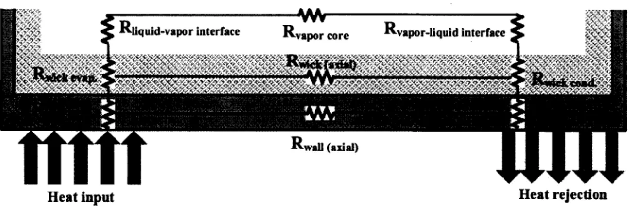
A heat pipe acts basically as a thermal resistance which will transfer a certain heat flux with a corresponding temperature difference between the evaporator and the condenser. In order to keep the electronics temperature in an acceptable range, this resistance should be minimized which will lead to a minimized temperature difference. A simplified representation o f transport in heat pipes may be described by a thermal resistance network [18]. Due to much lower values o f wick and vapor core axial resistances, they are usually ignored compared with other resistances and evaporator thermal resistance is considered to be the dominant resistance [54]. Therefore, to decrease the overall thermal resistance o f the heat pipe, evaporator thermal resistance should be reduced.
Rliquid-vapor interface vapor core vapor-liquid interface «5
mm,
/.V..V ,V ,.V ,V A ^
■aa.friifr.ii
wall (axial)
Heat i n p u t Heat rejection
is depicted here)
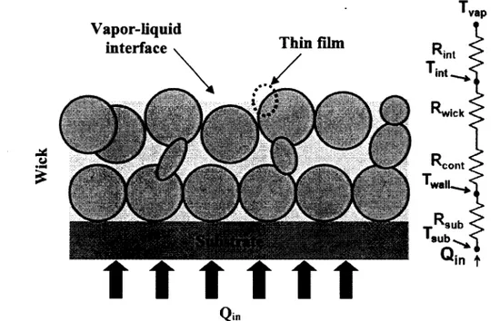
During heat pipe operation, heat is conducted from the substrate through the saturated wick (Figure 2.2). Due to lower conductivity o f the liquid, most o f the heat is conducted through the wick structure to the wick surface. At the surface, heat transfer occurs mainly in the thin liquid film region o f several microns thickness [49]. The liquid thickness in the thin film region is around 10 pm and it is responsible for up to 55% o f the total meniscus mass transfer. This is caused mainly by the very low thermal resistance due to very thin liquid layer.
Vapor-liquid interface \
Q i n
Figure 2.2 Schematic drawing o f liquid saturated wick and its associated thermal resistance
The heat transfer at the surface depends on the thin film area, its thickness and also the effective conductivity o f the saturated porous wick [30]. A wick with low evaporation resistance is characterized by a low thermal resistance o f the saturated wick R wick and the liquid-vapor interface Rint. However, it is shown that Rint is dominant only in the case o f very thin wicks (~100 pm) [62]. Consequently, investigating mechanisms affecting wick thermal resistance across the wick thickness in the evaporator section such as meniscus recession is another focus o f the current research which will be presented in chapter 6.
2.3 Project definition
The principal objective o f the current work is to understand the heat and fluid transport in copper metal foams as heat pipe wicks and thereby improve modeling and performance capabilities. The research question can be defined as: what are the mechanisms governing the heat and mass transport in the capillary driven phase change heat transfer in metal foams used as wick in heat pipes utilizing Metafoam materials? Due to the complicated nature o f transport in porous copper metal foams, an experimental approach is mainly chosen. After identifying capillarity and evaporation as the general phenomena governing heat pipe operation, experimental facilities are developed to further study these two phenomena in copper metal foams. Wetting, capillary and evaporation properties are measured which can be later used in numerical and design work.
2.4 Objectives of the thesis
Having an industrial partner in this project (Metafoam technologies), an effort was made to consider the partner’s interests as well as the scientific originality and contributions required for a PhD project. The industrial partner’s objectives are:
• Explanation on why heat pipes utilizing Metafoam’s materials have superior performance compared to competing materials
• Characterizing the performance o f metal foams for heat pipe applications • A numerical model o f heat pipe performance
To address these needs and also consider the requirements o f a PhD (novelty and originality), the following objectives are defined:
2.4.1 Capillary action
• Studying the wetting properties o f copper metal foams
• Characterizing the foam hydrophilicity loss in ambient air and its cause
• Measuring permeability and effective pore radius to investigate the effect o f porosity and a sintered external wall
2.4.2 Evaporation
• Investigating the capillary driven evaporation phenomena
• Investigating the effect o f different parameters such as porosity, and wall superheat on the rate o f evaporation.
• Measuring critical heat flux and wall superheat to investigate the mechanism o f heat pipe failure for different porosities
2.5 Original contribution
This project is the first work o f its type in the Micros research group and the first o f this type to ever investigate phase change phenomena in the porous copper metal foams as produced by Metafoam. Several original contributions o f this work can be mentioned as:
• By studying the foam microstructure, two levels o f porosities are identified which directly enhances thermal and fluid transport phenomena in these foams. This microstructure is unique in metal foams and is speculated to be the main cause o f high performance o f these foams compared with other wicking materials. Although no direct experiment is done to prove this point, it is supported by observations with other biporous (having two level o f porosity) wicks in the open literature and the similarity between the two. This point is discussed in chapter 4.
• It is found for the first time that the reason for hydrophilicity loss o f the copper metal foams when exposed to ambient air is the adsorption o f organic material and not copper oxidation. A very common misunderstanding as to the role o f the copper oxides is therefore corrected for the first time. A novel method is also developed to measure the rate o f hydrophilicity loss o f copper metal foams based on measuring the spreading time o f a droplet on the porous foam. This is the focus o f chapter 4.
• In this thesis, the first characterization o f K, reff, and internal contact angle for Metafoam copper metal foams is provided and also the conditions under which the rate o f rise measurements should be done for proper parameter extraction is clarified. It was found that the rate o f evaporation while the liquid is rising is significantly lower than the evaporation rate o f a saturated sample with stationary liquid. It was also observed that sintering copper walls has almost no effect on the capillary rise and on the evaporation rate. By combining measurements done with acetone and water, the internal contact angle o f water in hydrogen treated copper foams was measured and found to be lower than on a flat plate. Chapter 5 will focus on this topic.
• A novel experimental approach is proposed to measure the evaporation rate in chapter 6. Together with an analytical model, the effect o f meniscus recession on the capillary pumping o f copper metal pumps is characterized for the first time. The improved values o f effective pore radius found by this method can have significant impact on the prediction o f the capillary limits in two phase capillary driven devices. Moreover, occurrence o f minimum wick thermal resistance in the same heat flux where dryout happens and also where minimum meniscus radius exists shows the importance o f meniscus recession in the capillary driven transport phenomena in porous media.
• As the overall contribution o f this thesis, the interconnection between capillarity and evaporation in the porous media is shown for the first time here. This aspect is especially important because the link between the two requires the simultaneous investigation o f these two phenomena in the future researchworks.
CHAPITRE 3 AVANT-PROPOS
Auteurs et affiliation:
• Mahmood R.S. Shirazy: etudiant au doctorat, Universite de Sherbrooke, Faculte de genie, Departement de genie mecanique.
• Luc G. Frechette: professeur, Universite de Sherbrooke, Faculte de genie, Departement de genie mecanique.
Date d’acceptation: 13 mai 2010
Etat de 1’acceptation: version finale publiee
Revue: Proceedings o f ASME 2010 3rd Joint US-European Fluids Engineering Summer
Meeting and 8th International Conference on Nanochannels, Microchannels, and Minichannels, FEDSM2010-ICNMM2010.
Reference: [70]
Titre franf ais: Une etude parametrique des limites d’operation des caloducs
Contribution au document:
Cet article contribue a la these en determinant la limite d’operation dominante dans les caloducs utilisant des mousses metalliques en cuivre. Apres avoir connu la limite dominante dans cette etape, qui est la limite capillaire, on peut se concentrer sur les phenomenes qui se produisent du a cette limite. Done, la capillarite et 1’evaporation sont identifiees et sont etudiees dans les chapitres prochains.
Resume fran^ais :
Une etude parametrique a ete realisee pour etudier les limites d ’operation des caloducs utilisant un nouveau type de mousse metallique comme meche pour des applications de
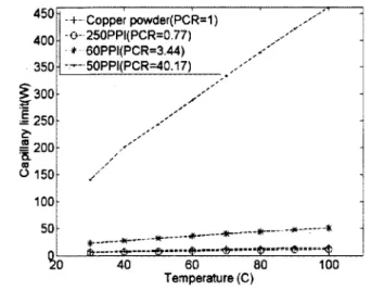
refroidissement des puces. Ces mousses ont une microstructure unique, formee de regroupements de pores spheriques avec une surface tres elevee par rapport au volume compare aux mousses metalliques traditionnelles. Elies presentent des limites d'operations plus elevees dans les tests preliminaires de caloducs, ce qui suggere des taux eleves de refroidissement pour des applications microelectroniques. Dans la premiere partie de cette etude parametrique, les correlations deja connues sont utilisees pour calculer les cinq types de limites de transfer! de chaleur (capillaire, ebullition, visqueuse, l'entrainement et sonore) en fonction de la temperature, le type de mousse, et la porosite. Les resultats montrent que la limite dominante est la plupart du temps la limite capillaire, mais pour la mousse de type de 50 pore-par-pouce (PPI), la limite d'ebullition sera dominante. En outre, les mousses de 50 et 60 PPI ont des limites superieures de transfert de chaleur que la poudre de cuivre frittee. Dans la deuxieme partie de cette etude, un modele thermodynamique en regime permanent d'un caloduc plat a ete fait pour etudier l'effet des differents parametres sur la limite dominante (capillaire). Un nombre sans dimension a ete propose pour evaluer l'equilibre entre la perte de charge dans les phases vapeur et liquide comme un guide de conception supplementaire pour ameliorer la limite capillaire des caloducs plats.
3 A PARAMETRIC INVESTIGATION OF
OPERATING LIMITS IN HEAT PIPES
3.1 Abstract
A parametric investigation has been performed to study the different operating limits o f heat pipes employing a novel type o f metal foam as wick for chip cooling applications. These foams have a unique spherical pore cluster micro structure with very high surface to volume ratio compared to traditional metal foams and exhibit higher operating limits in preliminary tests o f heat pipes, suggesting high cooling rates for microelectronics. In the first part o f this parametric study, widely used correlations are applied to calculate the five types o f heat transfer limits (capillary, boiling, viscous, entrainment and sonic) as a function o f temperature, type o f foam, and porosity. Results show that the dominant limit is mostly the capillary limit, but for 50 pore-per-inch (PPI) foam, the boiling limit will be dominant. Also, 50 and 60 PPI foams have higher heat transfer limits than sintered copper powder. In the second part o f this study, thermodynamic steady state modeling o f a flat heat pipe has been done to study the effect o f the different parameters on the dominant limit (capillary). A dimensionless number has been proposed to evaluate the balance between the pressure loss in the vapor and liquid phases as an additional design guideline to improve the capillary limit in flat heat pipes.
3.2 Introduction
Flat plate heat pipes (FHP) are capillary driven passive devices that are usually used for the thermal management o f electronic components. A flat heat pipe is a cavity o f small thickness filled with a two-phase working fluid [44]. Heat sources and heat sinks are typically located near the opposite extremities o f the heat pipe with the other parts being insulated. Evaporation occurs at the location o f the heat sources. The vapour travels along the heat pipe, transporting the extracted thermal energy to the heat sink zones where it condenses. The liquid returns from the condenser to the evaporator through a wick or capillary structure made o f micro
grooves, meshes, sintered powder wicks or metal foams. In the field o f electronic cooling, working temperatures are in the range o f 60 to 120 °C. At this temperature level, the commonly used fluids are acetone, methanol, ethanol or water.
The design and type o f capillary structure are main factors that influence the heat transfer capability o f a heat pipe [79]. Open cell metal foams are proposed as wicks in flat heat pipes. Metal foams are a good candidate for two phase and single phase chip cooling because they are thermally conductive, light weight, have a high surface area and can provide good thermal contact between the heat pipe wall and the wick. Novel open cell metallic foams can be fabricated with a wide range o f porosities, material composition, and micro structures, through a patented process initially developed at the National Research Council, NRC-IMI (Bourcherville, Qc, Canada) and now being manufactured and commercialized by the Canadian company Metafoam Technologies . These foams have a unique spherical pore cluster micro structure with very high surface to volume ratio compared to traditional metal foams and show good performance for heat transfer applications [58]. In preliminary tests, these foams exhibit higher operating limits in a heat pipe than common wicks, suggesting high cooling rates for microelectronics applications.
Although flat heat pipes are very efficient cooling systems, they are subject to a number o f classical heat transfer limitations [18]: continuum flow limit, frozen start-up limit, viscous limit, sonic limit, entrainment limit, capillary limit, condenser limit and boiling limit. These phenomena limit the maximum heat input that may be transported by a heat pipe; heat rates above these limit values result in failure. Frozen-start up limit is not usually encountered in electronics cooling applications and if the condenser is well designed and the heat pipe is free o f non-condensable gases, the condenser limit is not typically encountered either.
Modeling o f the operation and performance o f flat heat pipes has received a lot o f attention in two main categories: 1) the numeric or analytic simulation o f steady state or transient operation o f FHPs, and 2) the transport limits (mainly capillary and boiling) and dry-out lengths. Numerous studies exist on simulations o f flow and heat transfer inside FHPs [78] [80],
transport limits, and dry-out lengths [44, 54, 80, 87], but most o f these studies are performed assuming a grooved wick structure.
For instance, Lips et al. [1] studied the boiling limit o f a transparent flat grooved heat pipe. They showed that the onset o f nucleation does not prevent the operation o f the FHP and even enhances its performance. Due to experimental challenges, they cannot clearly show that the boiling limit is actually the dominant one (lower than the capillary limit). Dry-out in the evaporator is observed for heat fluxes much higher than the onset o f boiling. Hanlon et al. [6] attempted to describe the evaporation process in sintered copper wicks theoretically and by doing experiments. According to them, as the bubbles appear in the wick, the thermal performance o f the wick decreases. This result is opposed to [1] and is probably caused by the difference in nucleation mechanisms and bubble growth in grooves and sintered copper. It suggests that the mechanisms involved in failure o f a flat heat pipe are not the same for different material wicks and depend on the topology and microstructure o f the wicking material.
Only few studies have addressed the application o f metal foams as wicks in heat pipes. Phillips [56] studied the permeability, capillary pressures and evaporative performance o f different porous materials including high porosity metal foams in order to evaluate their performance as wicks in heat pipes. He concludes that from the capillary pumping point o f view, foam wicks are most desirable, felts rank second, and screens are least desirable. But for the onset o f nucleate boiling, felts are more convenient than foams. Carbajal et al. [8, 55] and Queheillalt et al. [61] have studied transient response o f a large flat heat pipe structure employing nickel foam as a wick, while exposed to a non uniform localized heat flux. Studies to date on metal foams have therefore focused on the wick properties or specific applications, but the relationship between these properties and operating limits remains to be investigated. A survey o f the literature does not indicate significant efforts, both at macroscopic and microscopic levels, to study the performance o f metal foams in flat heat pipes for electronics cooling applications. Further understanding o f phase change alongside capillary driven flow,
and also its corresponding relationship to heat pipe limits, are important for efficient flat heat pipes. The current study aims to take an initial step towards this goal.
In order to evaluate the possibility o f using the available correlations for calculating the operation limits o f a heat pipe with a metal foam wick, and to identify the important design parameters affecting the dominant operating limit, a parametric study has been done in two parts. In the first part, correlations commonly used in the field to calculate the heat pipe limits have been employed to determine different operating limits o f a typical circular heat pipe. The circular geometry has been chosen in order to use the existing correlations for ordinary heat pipes. In the second part, thermodynamic steady state modeling o f a flat heat pipe has been done to study the effect o f the different parameters on the dominant limit, determined in the first part. Here, a rectangular (flat) geometry has been chosen. The main difference between the flat plate and cylindrical geometries is the vapor core cross section. It will be seen that the thickness o f the vapor core has considerable impact on the general performance o f a FHP. Overall, this device level study will define the research topics that are most critical to further investigate for accurate predictive modeling o f FHP with metal foams.
3.3 Nomenclature
Av Vapour core cross section area (m2) Aw Wick cross section area (m2)
C Constant depending on Mach number D Flat heat pipe width (m)
hv Vapor core height (m) hi Wick thickness (m) K Permeability (m2)
k e f f Effective thermal conductivity L e f f Effective length o f the heat pipe (m)
Le Evaporator length (m) Lc Condenser length (m)
L a d i Adiabatic length (m)
M Molecular weight
Mav Vapour core mach number ” K Vapor mass flow rate (kg/s.m) P c , m Capillary pressure (Pa)
P v Vapour pressure (Pa) P i Liquid pressure (Pa)
Q t o t Heat power injected in the evaporator (W) qa Heat flux (W/m2)
q Heat transfer rate (W) R v Vapor constant (J/kg.K)
R Universal gas constant (J/ mol.K) Rev Reynolds number
l " h , v Vapor core radius (m) rc Pore capillary radius (m) rn Nucleation radius (m)
l " h , w Surface pore hydraulic radius (m) T . Vapor temperature (K)
T v Vapour temperature (K) wv
Mean velocity o f the vapor in the x direction (m/s)
w, Mean velocity o f liquid in the x direction (m/s)
M, Liquid viscosity (N.s/m2) Mv Vapour viscosity (N.s/m2)
Vv Vapour kinematic viscosity (m /s) Vl Liquid kinematic viscosity (m /s)
X Latent heat o f vaporization (J/kg) p v Vapour density (kg/m3)
p t Liquid density (kg/m ) 6 Contact angle (°) a Surface tension (N/m)
3.4 Operating limit correlations
3.4.1 Capillary limit
The most commonly studied limitation in flat or miniature heat pipes is the capillary limit [10, 40, 87]. The driving potential for the circulation o f the working fluid is the capillary pressure difference. Capillary limit occurs if the maximum capillary pressure is not enough to overcome the sum o f all pressure losses (due to liquid friction, vapor friction, and gravity) inside the heat pipe. This can be expressed as [54]:
2a cos 9 ( C (/v R e > v ] L e f f 9 +
( \
M, r c {2(rhJ \ p vX ) { KAwXp,J
The left-hand term is the maximum capillary pressure produced by the porous structure, where a is the surface tension, 9 is the contact angle (assumed to be zero here) and rc is the pore capillary radius. The first term at the right side o f Eqn 3.1 expresses the vapor core pressure drop, w here^ is the vapor viscosity, n ,v vapor core radius, A v vapor core cross section area, Ps vapor density, k latent heat o f vaporization, q is the rate o f heat transferred and Leff is the effective length o f the heat pipe (l€ =0.54+1^ +0.5Z,C). The normal hydrostatic pressure is neglected in this equation because o f the small inside diameter o f the tube. The axial hydrostatic pressure can also be neglected if the heat pipe is assumed to be horizontal. The
constant C depends on the Mach number and determines the compressibility o f the flow inside the vapor core. The Mach number can be defined as:
Mav = ---3--- t/2 ApA K Tj , ) '
3.2
where Rv is the gas constant, Tv is the vapor temperature andyv is the ratio o f the specific heats (1.33 in this case). The vapor flow regime (laminar or turbulent) can be determined by evaluating the local axial Reynolds number in the vapor. The Reynolds number appears in Eqn 3.1 as a product with the friction factor: / vRev. Reynolds number in the vapor core is defined as:
The values for these two parameters, C a n d /vRev, depend on Rev and Mav, according to:
Rev <2300 & M av < 0.2 / v Rev =16 C=1.00 Rev < 2300 & Mav > 0.2
Because the equations used to evaluate both the Reynolds number and the Mach number are functions o f the heat transport capacity, it is first necessary to assume the conditions o f the vapor flow. Using these assumptions, an iterative procedure must be used to determine the maximum heat capacity. Once this value is known, it can be substituted into the expressions
3.5
Rev > 2300 & Mav > 0.2 ( 2 ( r . ) q Y
f Re =0.38 v hy)H C=1.00
![Figure 1.2 Metafoam copper foam wicks for heat pipe and vapor chambers[58]](https://thumb-eu.123doks.com/thumbv2/123doknet/2836788.69031/18.918.326.585.641.795/figure-metafoam-copper-foam-wicks-heat-vapor-chambers.webp)