HAL Id: hal-01666713
https://hal.archives-ouvertes.fr/hal-01666713
Submitted on 13 Dec 2018
HAL is a multi-disciplinary open access
archive for the deposit and dissemination of
sci-entific research documents, whether they are
pub-lished or not. The documents may come from
teaching and research institutions in France or
abroad, or from public or private research centers.
L’archive ouverte pluridisciplinaire HAL, est
destinée au dépôt et à la diffusion de documents
scientifiques de niveau recherche, publiés ou non,
émanant des établissements d’enseignement et de
recherche français ou étrangers, des laboratoires
publics ou privés.
Analysis of the friction and wear behaviour of hot work
tool steel for forging
Olivier Barrau, Christine Boher, R Gras, Farhad Rezai-Aria
To cite this version:
Olivier Barrau, Christine Boher, R Gras, Farhad Rezai-Aria. Analysis of the friction and wear
be-haviour of hot work tool steel for forging. Wear, Elsevier, 2003, 14th International Conference on Wear
of Materials (WOM SI) 30 March-3 April 2003
• Washington, DC, USA, 255 (7-12), pp.1444-1454.
�10.1016/S0043-1648(03)00280-1�. �hal-01666713�
Analysis of the friction and wear behaviour
of hot work tool steel for forging
O. Barrau
a, C. Boher
a,∗, R. Gras
b, F. Rezai-Aria
aaEcole des Mines d’Albi-Carmaux, CROMeP, Campus Jarlard, Route de Teillet, CT 81013 Albi Cedex 09, France bISMCM-CESTI, 3 Rue Ferdinand Hainaut, 93047 Saint-Ouen Cedex, France
Abstract
A significant part of the energy in forging is used to break the interfacial junctions due to friction between the tool and the workpiece. The life of hot-forging tools is usually limited by complex interactive mechanisms under cyclic loading such as abrasive, adhesive and scaling wear, thermal and mechanical fatigue, and plastic deformation.
This contribution deals with the wear mechanisms of the tempered martensitic X38CrMoV5 steel (AISI H11) under high-temperature and dry-sliding wear. The investigations are carried out with high-temperature pin-on-disc tests. The pin is cut from bars of X38CrMoV5 steel treated at 42 and 47 HRC. The disc is made of common steel (AISI 1018, XC18). Temperature of the disc ranges from 20 to 950◦C. Before the test starts, the disc is first pre-heated for 1 h. The experiments are performed under constant load and velocity. The friction coefficient decreases quasi-linearly with the rising disc temperature up to 800◦C. Over this temperature, it decreases drastically for the 42 HRC steel but remains linear for the 47 HRC steel.
Scanning electron microscopy (SEM) and energy dispersive spectrometry (EDS) investigations have revealed that wear is essentially due to abrasion, plastic deformation and fatigue. Set of cracks due to contact rolling fatigue is observed on the pin and the disc. Those cracks are located on the transferred scale on the pin and on the oxide scale of the disc wear track. The cross-section observations of the pin have revealed a plastically deformed zone beneath the surface. In this sub-surface layer, the tempered martensitic microstructure seems to be more aligned due to friction and the plastic deformation.
Keywords: Friction; Wear; Hot forging; Plastic deformation
1. Introduction
A specific disadvantage of the hot and warm die-forging process is that the tools are exposed to high thermal and mechanical stresses. These stresses cause failure of the dies because of wear and thermo-mechanical fatigue[1–5]. The tools then have to be exchanged after a certain time of use. It leads to considerable costs not only for the tools themselves but also for the needed set-up times and thus may cause delays in delivery of the forged parts.
The hot working steels usually used for the die-forging tools are exposed to tempering effects because of high ther-mal and mechanical loads. These tempering effects on their part cause a greater susceptibility to wear.
Generally, due to the forging temperature being well above 1000◦C, the temperature of the surface of the tool temporarily exceeds 500◦C [1–3] and thus the tempering temperatures of conventional hot work tool steel. In such a
∗Corresponding author. Fax:+33-563493242.
E-mail address: boher@enstimac.fr (C. Boher).
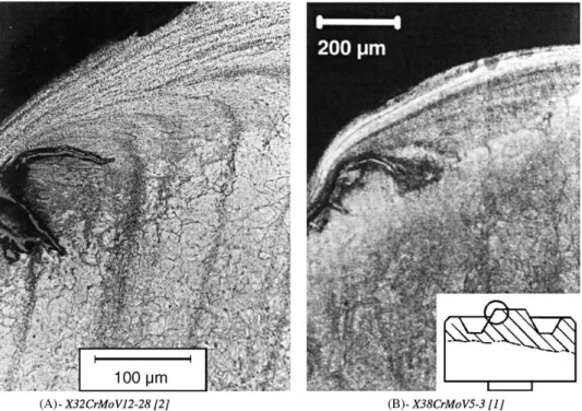
case, the hardness of the tool is reduced and the mechanical impacts during forging operations can easily cause plastic deformation as well as abrasion of tool material[1](Fig. 1). In fact, for each fabrication operation, temperature vari-ations occur more or less quickly on the working tool sur-face due to the heat exchange between the hot workpiece and the tool. After contact with the hot workpiece, the die surface is quickly cooled. Then, transient thermal gradients are developed inside the tool by thermal conduction. These thermal gradients lead to crack the surface by heat checking
[4].
Besides, tools undergo mechanical strains during forging
[3]. These strains can enhance diffusion pathways in the die oxidation that plays an important role in the tool wear. The damage caused by friction may be very different according to the nature and the physical properties of the contact surfaces (metal or formed oxide layers).
At last, under thermal and mechanical stresses, the tem-pered martensitic steels employed in hot-forging tools are inclined to loose their mechanical properties [4–6]. Also, the die surface damage is the result of a complex process
Fig. 1. Microstructure of the convex radius of different hot work tool steels after 1000 forging cycles. Tool temperature, 200◦C; forging material, C45; forging temperature, 1100–1150◦C; lubricated contact; cycle time, 13 s; hardness of tools, 47 HRC.
connected to fatigue (cracking origin), friction (wear origin) and test ambience (oxidation origin)[3].
The aim of this contribution is to assess some wear mechanisms of a tempered martensitic tool steel at various test temperature and initial hardness. The friction tests were performed on a high-temperature pin-on-disc tribometer developed in our laboratory, in order to control load, speed, temperature, surface conditions and chemical state of the materials.
2. Experimental equipment, procedure and materials
2.1. High-temperature pin-on-disc tribometer
The high-temperature pin-on-disc tribometer developed in our laboratory is reported in [7,8]. The pin presents a hemispherical contact surface with a radius of curvature of 20 mm. The disc is a cylinder of 30 mm diameter.
After each test, wear surfaces are observed by optical mi-croscopy and/or scanning electron mimi-croscopy (SEM) with dispersive energy analysis capability. To complete these in-vestigations, a cross-section observation on each pin is also performed on an environmental SEM (ESEM).
2.2. Test procedure
The disc is first heated up to a given temperature and kept it constant for 1 h. During the disc pre-heating, the pin is kept out of the contact at room temperature. After 1 h of
heating of the disc, the pin is put on the disc surface and the friction test is started immediately.
To assess the effect of the disc temperature on wear dam-age, the normal load (20 N) and the linear sliding speed (0.167 m s−1) are kept constant. Test conditions are sum-marised inTable 1.
It is considered that the temperature of the forging tools do not reach the high temperatures applied in the test (800 and 950◦C). The temperature of the forged piece is often over 1000◦C, so temperature of the tool surface may reach these temperatures. Therefore, tests are conducted at these temperatures to assess their influence on the wear behaviour of X38CrMoV5.
2.3. Materials
The pin is made of a 5% chromium tempered martensitic steel grade (X38CrMoV5, AISI H11). On the other hand, the disc is a ferritic-pearlitic mild steel (XC18, AISI 1018). The X38CrMoV5 steel is widely used for forging dies [9,10], whereas AISI 1018 mild steel is used as a forged material in automotive industry. The chemical composition of the two steels is reported inTable 2.
Table 1
Friction test conditions
Pin initial hardness (HRC) 42 or 47
Normal load (N) 20
Sliding speed 100 rpm (rotate); 0.167 m s−1 (linear)
Test duration (s) 3600
Table 2
Chemical composition of test materials
Elements (wt.%) C Cr Mn V Ni Mo Si P S Fe
Pin: X38CrMoV5/AISI H11 0.40 5.05 0.49 0.47 0.20 1.25 0.92 – – Balance
Disc: XC18/AISI 1018 0.16–0.22 <0.40 0.40–0.70 – <0.40 <0.10 0.15–0.35 <0.035 <0.035 Balance
Table 3
Heat treatment procedure to achieve tempered martensite microstructure for X38CrMoV5 steel
Hardness (HRC) Austenisation First tempering Second tempering
42 990◦C/1 h/air 550◦C/2 h/air 625◦C/2 h/air
47 990◦C/1 h/air 550◦C/2 h/air 603◦C/2 h/air
The 5% chromium steel was studied in quenched and tempered conditions. The heat treatments are performed to achieve two initial hardnesses, 42 and 47 HRC, with a tem-pered martensitic microstructure (Table 3). The tempered martensitic structure is in fact ferrite and cementite with a lath shape. The microstructure has a high density of dis-locations, which gives a good strength to the material at room temperature[11]. At high temperature, the interpre-cipitates distance increases, so the mobility of dislocation is enhanced.
The initial hardness of AISI 1018 steel is about 168 HV at room temperature. The initial arithmetic roughness of the disc and the pin are 0.04 and 0.32 !m, respectively.
3. Friction and pin damage
3.1. Friction evolution
First, the average value of the coefficient of friction de-creases with an increase of the test temperature (Table 4) regardless the initial hardnesses of the pin. The friction coefficient versus time curves for a given test tempera-ture are quite similar for both initial hardnesses of the pin substrate.
At room temperature and 200◦C, the mean value of the friction coefficient of the couple X38CrMoV5/XC18 is about 0.6 of whatever the initial hardness of the pin is. This friction coefficient is generally found for steels in dry friction. From 500 to 800◦C, the average value of the coef-ficient of friction decreases slightly to 0.5 and there is still
Table 4
Evolution of friction coefficient vs. the disc temperature Hardness (HRC) Average friction coefficient (µ)
20a 200 500 700 800 950
42 0.60± 0.045 0.63± 0.050 0.53± 0.020 0.46± 0.045 0.45± 0.044 0.19± 0.040
47 0.59± 0.060 0.60± 0.041 0.49± 0.020 0.52± 0.020 0.44± 0.050 0.36± 0.049
aDisc temperature (◦C).
not a significant difference between pins with two levels of hardness.
Over 800◦C, the value of the friction coefficient decreases but its evolution remains quite linear for the 47 HRC initial hardness pin while it decreases drastically for the 42 HRC pin. So, 950◦C seems to be a critical point from which the friction behaviour of the couple X38CrMoV5/XC18 is modified depending on the disc temperature and the pin hardness.
The overall decreases of the friction coefficient may be connected to the loss of the mechanical properties with the increase of the test temperature[4–6]and to the presence of an oxide layer for the high-temperature test. It seems that the 42 HRC initial hardness pin looses its mechanical properties quicker than the one of 47 HRC.
3.2. Surface observations
The damaged surfaces of the pin are observed by SEM for each test temperature. The surface damages of the pins up to 800◦C, were already presented in previous works[12]. No difference was observed between the 42 and 47 HRC pin at the same test temperature but the pin wear track changes with the temperature.
Under 500◦C, we claim that tribo-oxidation is prevail-ing. The metallic debris enter into the contact region and are oxidised during the sliding. At 500◦C, a two zones layer constitutes the wear track. The light zone is the matrix of the pin and the dark area is oxides from the disc and oxi-dised debris. These zones form a metal-oxide mixed zone. Beyond 500◦C, hot tribology prevails: the sliding contact surfaces generate debris already oxidised mainly from the disc surface. At 700◦C, this mixed zone is gradually trans-formed in a compacted layer of oxide debris which tends to become glazed at higher temperature. At 800◦C, the mixed zone becomes totally glazed surface. These glazed surfaces present cracks.
At 950◦C, the contact surfaces are oxide on oxide. Even though there is an important difference between the value of
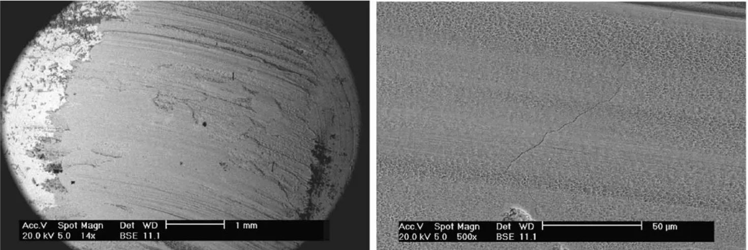
Fig. 2. Wear track of the pin after the test at 950◦C.
the coefficient of friction of the 42 and 47 HRC pin for this test temperature, the morphology of the contact surfaces is quite similar for the both hardnesses (Fig. 2A). We observe a compacted oxide layer on the surface of the pin. The mor-phology of this layer looks like an iron oxide (Fe2O3). This
oxide on the pin surface may come from the oxide formed on the disc during the pre-heating treatment. As can be seen inFig. 2B, the surface oxide morphology is modified on the contact area between the pin and the disc. This deformation looks like an indentation which tends to transform oxide into glazed zone.
In addition, another damage mechanism contributing to the wear in the couple X38CrMoV5 steel on XC18 steel is the surface oxide layers cracking for the temperature ranging 500–950◦C. We do not observe cracks for the lowest tem-peratures[12]. The form of the cracks suggests their phys-ical origin. The fatigue cracks have a horseshoe form. We could attribute the superficial fatigue cracks to friction stress but the thermal stress generated during the cooling can as well cause such cracking.
3.3. Cross-section observations
The cross-sections of the pin are observed by ESEM for each test temperature. The cross-sections are cut parallel to the direction of friction. Some energy dispersive spectrom-etry (EDS) analyses were added to complete the investiga-tions. Results from EDS are mainly qualitative.
3.3.1. Plastic deformation
We observe plastic deformation parallel to the direction of friction for each test except at 950◦C. The maximum thick-ness of sub-surface layer affected by the plastic deformation versus temperature is summed up inTable 5.
From 20 to 200◦C, the flow stress of the 47 HRC is high and do not allow a large plastic deformation. So, the values
measured for these temperatures are a bit lower than for the 42 HRC alloy. Up to 500◦C, the measured deformed thickness is quite similar for the two pin hardnesses. At 700◦C, the behaviour changes between the both hardnesses. The resultant thickness deformed on the 42 HRC is more than five times larger than the deformation observed on the 47 HRC pin.
The maximum thickness affected is often measured near the back of the wear track due to the flow of matter, as we will see later on. When it is observed, the plastic de-formation is influenced by the initial orientation of the lathes of the microstructure as we can see inFig. 3. If the lathes have an angle with the surface beyond π/2, it lim-its the thickness affected. If this angle is below π/2, the lathes are easier to deform and the deformed zone becomes thicker.
At 20◦C, for the both hardnesses, we observe a plasti-cally deformed zone. But the elongation of the lathes is less important compared to those measured at higher tempera-tures even if the values of the resultant thickness deformed are very close (Fig. 4A and B).
In localised zones, for the low-temperature test (20 and 200◦C), the shape of the plastic deformation rather looks like of an indentation by a normal force than a plastic de-formation under shear force (Fig. 5). This indentation may occur when two metallic asperities enter in contact (Fig. 5A)
Table 5
Evolution of the maximum thickness affected by the plastic deformation vs. the disc temperature
Hardness (HRC) Plastic deformation maximum (!m)
20a 200 500 700 800 950
42 5 14 5 11 5 –
47 3 10 5 2 2 –
Fig. 3. Plastic deformation on the surface of the pin. Influence of the initial orientation of the lathes.
Fig. 4. Plastic deformation on the surface of the pin.
Fig. 6. Surface of the pin after the test at 500◦C.
or it may form due to the hardness of the debris in the con-tact for these test temperatures (Fig. 5B).
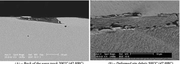
In the back of the wear track, we observe an edge of de-formed material created by the movement of matter under shear force (Fig. 6A). It is at the back of the wear track where we measure the maximum thickness affected by plastic de-formation. Even if the maximum strain due to the normal load and velocity is localised in front of the wear track. As we can observe inFig. 6B, some big debris are abraded and plastically deformed. The formation of such debris could explain the low resultant thickness observed at and over 500◦C peculiar for the 47 HRC pin. These big debris could easily be abraded from the edge at the back of the wear track.
The formation of dimples, in the plastically deformed zone, near the external surface of the matrix plays a role in the decohesion of the lathes (Fig. 7B). The lathes reach their maximum deformation and microductile cavities ap-pear when the material can not be more deformed.
Fig. 7. Surface of the pin after the test at 200◦C (47 HRC).
Cavities have been formed at the interface deformed zone–matrix (Figs. 7A and 8A), but they also have been formed by the flow of matter under shear force (Fig. 8B). The formation of these cavities may occur at the prior austenite grain boundary. These cavities also play a role in the debris emission.
From 700 to 800◦C, the difference between the two initial pin hardness becomes greater: there is only little resultant thickness affected by the plastic deformation on the 47 HRC. However, we find some big debris of the pin plastically deformed on the wear track. These big debris contribute to the low deformed thickness that was measured. At 950◦C, the matrix has completely lost its mechanical properties and the plastic deformation consists of movement of matter like a viscous flow (Fig. 9).
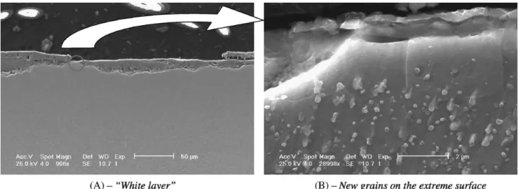
3.3.2. Microstructure evolution
It remains the same as initial tempered martensite mi-crostructure for the whole tests except at 950◦C. For this
Fig. 8. Surface of the pin after the test at 700◦C (42 HRC).
test temperature, we observe a loss of the lath structure go-ing with the carbide coalescence and the formation of new grains on the extreme surface (Fig. 10B). The global aspect is close to the “white layer” observed by Walter et al.[2]
(Fig. 10A). These grains have the same composition of the initial X38CrMoV5 (5.33 wt.% Cr; 1.7 wt.% Mo; 0.69 wt.% V; 1 wt.% Si; 0.43 wt.% Mn).
For the 42 HRC pin at 950◦C, these grains are only ob-served outside of the wear track (2–3 !m height). For the 47 HRC pin, these new grains are observed on the whole sur-face but they are smaller in the wear track (2–3 !m height in the wear track; 4–5 !m height out of the wear track) (Fig. 10B).
We observe that the carbides are missing on the top of grain. Beneath the surface, carbides have the tendency to take a preferential orientation along the friction direction at the interface new grain–pin matrix.
3.3.3. Influence of oxide and oxidation on friction
From 20 to 200◦C, the oxide debris present in the contact region result from the abrasion of the surface asperities of
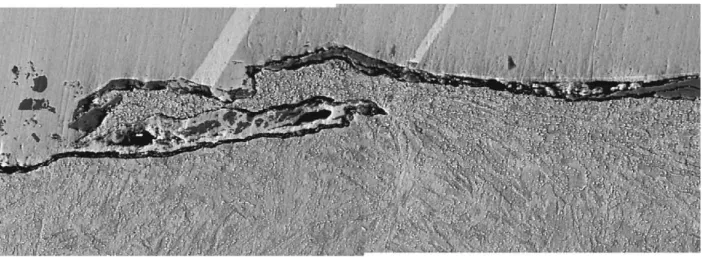
Fig. 9. Back of the wear track of the pin after the test at 950◦C (42 HRC).
pin and disc. The debris enter into the contact as metallic debris and are oxidised in the contact under shear force.
At 500◦C, there is a transition: we find metallic debris oxidised but also oxide debris mainly from the disc. The al-ternation of the metallic and the oxidised zone is character-istic of the mixed zone observed on the surface of the wear track for this test temperature.
At 700◦C, we observe localised oxidation of the X38CrMoV5. These oxides are very rich in chromium and molybdenum (18 wt.% Cr; 9.5 wt.% Mo; 1.17 wt.% Si). However, we do not observe depletion of these elements in the matrix around the oxide. We also remark an internal ox-idation at the lath boundary where carbides rich in alloyed elements are located (Fig. 11A).
This inter-lath oxide is rich in chromium peculiar to the oxidation of the X38CrMoV5 [13] and in molybdenum proper to inter-lath carbides (14 wt.% Cr; 5.8 wt.% Mo; 1.2 wt.% Si). This oxidation may lead to the decohesion of tempered lathes.
We also observe internal oxidation out of the wear track (Fig. 11B). These oxides are always very rich in alloyed
Fig. 10. Microstructure over-etched on the surface of the pin after the test at 950◦C (47 HRC).
elements (16.7 wt.% Cr; 5 wt.% Mo; 4 wt.% Si; 1.62 wt.% V). This oxidation seems to follow a preferential way of diffusion that can be a prior austenitic grain boundary.
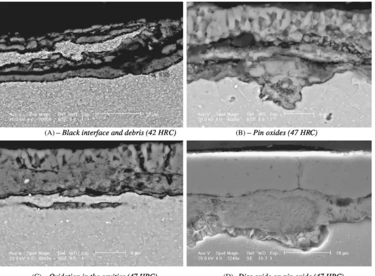
At and over 800◦C, we note the presence of a continuous oxide on the whole surface of the pin. This oxide scale (the black interface on theFig. 12A) locates between the matrix and the disc oxide (1.76 wt.% Cr). This interface may be a pin oxide (6.67 wt.% Cr; 3.1 wt.% Mo; 1.2 wt.% Si; 0.92 wt.% V): the presence of vanadium is proper to the pin. Below 800◦C, there are oxides but they are not continuous on the whole pin surface. Like at 700◦C, we observe an inter-lath oxidation leading to the emission of big debris. The oxides coming from the disc are thicker and very adherent to the pin surface (Fig. 12B).
At 950◦C, we find oxides from both the disc and pin on the surface of the pin. We also find debris of the matrix whose microstructure looks like the one of the pin at the surface (Fig. 13A). As at 800◦C, we remark a thin interface
Fig. 11. Oxidation on the surface of the pin after the test at 700◦C (47 HRC).
(1–1.5 !m) very rich in chromium (13.3 wt.% Cr). This in-terface is present and constant on the whole surface.
We also find on the surface of the pin multi-layer oxide. All these oxides contain chromium (1.5–12 wt.% Cr) and vanadium proper to the pin (Fig. 13B). The concentration of alloyed elements decrease moving closer the external sur-face. We observe oxidation in the cavities in the under-layer (Fig. 13C). These oxides are rich in chromium and silicon (9.7 wt.% Cr; 2.3 wt.% Si).
InFig. 13D, we note the presence of oxides from the disc. These oxides are compacted under normal force. So, these layers of oxides tend to crack due to their fragility, more particularly during the cooling stage after the test, but also under the shear force. We note the smooth and rectilinear shape of the surface in contact with the disc (Figs. 10A and 13D).
With the increase of the test temperature, the oxides be-come thicker on the disc surface and their contribution on
Fig. 12. Oxide and oxidation on the surface of the pin after the test at 800◦C.
friction is not negligible especially the abrasive effect of the hematite which can reduce the affected zone by plastic de-formation.
4. Discussion and conclusion
Whatever the test temperature, we note the presence of a plastic deformation of the lathes of the tempered marten-sitic steel. With an increase of the pin temperature, the lathes are easier elongated, i.e. the allowed plastic defor-mation increases. In addition, the initial orientation of the lathes influences the plastically deformed thickness of the sub-surface of the pin.
At 20◦C, the abrasive effect of the metallic debris gen-erated in the contact, justifies the low resultant thickness deformed plastically (mostly by indentation). From 200 to 500◦C, the X38CrMoV5 steel mechanical properties de-crease and the deformed zone becomes thicker due to the increase of the ductility. The high density of dislocations in our material allows strong deformation before rupture. The movement of the dislocation is thermally activated. We suppose there is a competition between abrasion and deformation leading to a damage cycle. The duration of this cycle may vary according to the initial hardness of the pin or the test temperature. The existence of a such cycle may justify the differences in the damage observations: at 200◦C, the ductility is predominant. At 500◦C, the abra-sion phenomenon gets over the ductility and limits the resultant thickness deformed. The appearance of the oxides contributes to the abrasion, especially hematite.
Between 20 and 500◦C, with the increase of the test tem-perature, the oxides become thicker on the disc surface and their contribution on friction is not negligible especially the abrasive effect of the hematite which can reduce the resul-tant affected zone by plastic deformation.
Over 500 and until 800◦C, for the 42 HRC pin, the resul-tant plastic deformation induces the formation of cavities at the triple point of the prior austenitic grain boundary. For these temperatures, the macroscopic shearing at the inter-face generated friction coefficient superior to 0.4 that leads to significant macroscopic shear stress.
At the prior austenitic grain scale (about 15 !m of grain radius), the 42 HRC allows an elongation of 160% before breaking (measured on the lath elongation in the deformed zone of the micrography). The emission of debris is governed by this elongation capacity of the lathes.
For the 47 HRC material, at the prior austenitic grain scale, the stress accommodation is not took in charge by the plastic deformation: so we observe abrasion and debris emission.
The difference of abrasion resistance between the two hardnesses seems to be due to the difference of microstruc-ture: size and density of carbides and also the dislocations density.
For the higher test temperature, we observe internal oxi-dation which contributes to the decohesion of pin debris. At
950◦C, the 42 HRC material has a viscous behaviour due to the loss of mechanical properties.
In brief, at the lath scale, the 47 HRC pin has a brittle behaviour which leads to the emission of big debris, even when the 42 HRC allows a “superplastic” deformation (up to 160% of deformation at the lath scale). So, at 700 and 800◦C, the 42 HRC pin is more ductile than the 47 HRC.
The thickness of the plastic deformation is maximum in the back of the contact but the maximum shear stress is in the front of the wear track. It is the flow of matter from the front to the back of the wear track which creates this edge of plastically deformed zone.
The presence of cavities and dimples are a consequence of the plastic deformation. Their size is about a few microm-eters but they can influence the emission of big pin debris.
The oxides present at high temperature play the role of solid lubricant by forming glazed surfaces. They also con-tribute to the enlargement of the wear track that increases the contact surface and therefore decreases the strain and the friction coefficient. The loss of mechanical properties also tends to reduce the friction coefficient especially for the test at 950◦C where the material has a viscous behaviour. The emission of big debris due to the bad ductility of the 47 HRC pin may explain the higher value of the friction coefficient for the higher test temperatures.
For the high temperature, we could think that the decrease of the friction coefficient could reduce the thickness plasti-cally deformed (via the decrease of the shear force), but the loss of the mechanical properties leads to a strong plastic deformation of the tempered martensitic lathes.
The continuation of this study will assess the relation be-tween the macroscopic test parameters and the microscopic damages observed at the extreme surface of the pin.
Acknowledgements
The authors gratefully acknowledge PSA Peugeot-Citroën for supporting these investigations, especially, Mr. Marc Plateau. Dr. Sylvain Jean, from EMAC, is also thanked for his technical assistance in ESEM observations.
References
[1] G. Andreis, K.-D. Fuchs, I. Schruff, The wear behaviour of hot-work tool steels used in forging processes, in: Proceedings of the Fifth International Conference on Tooling, Loeben, 1999, pp. 593–600. [2] S. Walter, H. Haferkamp, M. Niemeyer, Fr.-W. Bach, A. Henze,
Material failure mechanisms of forging dies, in: Proceedings of the Fifth International Conference on Tooling, Loeben, 1999, pp. 215–224.
[3] D. Kircher, H. Michaud, V. Bogard, Analyse des dégradations d’outillages de forge à chaud à l’aide de la simulation numérique, Mater. Technol. 1–2 (1999) 31–38 (in French).
[4] S. Jean, B. Miquel, S. LeRoux, P. Lamesle, F. Rezai-Aria, Heat-checking of hot work tool steels, in: Proceedings of SF2M of Temperature–Fatigue Interaction, May 2001.
[5] E. Doege, H. Nägele, U. Schliephake, Aspect of wear prediction in precision forging, Proc. Inst. Mech. Eng. B: J. Eng. Manuf. 208 (1994) 111–119.
[6] D. Delagnes, F. Rezai-Aria, C. Levaillant, A. Grellier, Influence of temperature and initial hardness on fatigue behaviour and life of a 5% Cr hot work tool steel, in: Proceedings of the Fifth International Conference on Tooling, Loeben, 1999, pp. 195–204.
[7] C. Vergne, C. Boher, R. Gras, Analysis of the friction and wear behavior of hot work tool scale: application to the hot rolling process, Wear 250 (2001) 322–333.
[8] C. Vergne, Ph.D. thesis, Ecole des Mines de Paris, France, 2001. [9] ASM Handbook, ninth ed., Forming and Forging, ASM 14, 1988.
[10] R. Leveque, Techniques de l’Ingénieur, Métallurgie M330 (1998) 1–42.
[11] N. Mebarki, D. Delagnes, P. Lamesle, F. Delmas, C. Levaillant, Relationship between microstructure and mechanical properties of a 5% Cr hot work tool steel, in: Proceedings of the Sixth International Conference on Tooling, Karlstad, 2002.
[12] O. Barrau, C. Vergne, C. Boher, F. Rezai-Aria, R. Gras, Investigations of friction and wear mechanisms of hot forging tool steels, in: Proceedings of the Sixth International Conference on Tooling, Karlstad, 2002.
[13] S. Jean, Ph.D. thesis, Institut National Polytechnique de Toulouse, France, 1999.