HAL Id: hal-01494471
https://hal.archives-ouvertes.fr/hal-01494471
Submitted on 23 Mar 2017
HAL is a multi-disciplinary open access
archive for the deposit and dissemination of
sci-entific research documents, whether they are
pub-lished or not. The documents may come from
teaching and research institutions in France or
abroad, or from public or private research centers.
L’archive ouverte pluridisciplinaire HAL, est
destinée au dépôt et à la diffusion de documents
scientifiques de niveau recherche, publiés ou non,
émanant des établissements d’enseignement et de
recherche français ou étrangers, des laboratoires
publics ou privés.
Indoor MIMO Channel Sounding at 3.5 GHz
Hanna Farhat, Yves Lostanlen, Thierry Tenoux, Guy Grunfelder, Ghaïs El
Zein
To cite this version:
Hanna Farhat, Yves Lostanlen, Thierry Tenoux, Guy Grunfelder, Ghaïs El Zein. Indoor MIMO
Channel Sounding at 3.5 GHz.
IEEE Middle East Conference on Antennas and Propagation,
(MECAP ‘16), Associations in Antennas & Propagation, Sep 2016, Beyrouth, Lebanon. pp.1-4,
�10.1109/MECAP.2016.7790107�. �hal-01494471�
Indoor MIMO Channel Sounding at 3.5 GHz
H. Farhat
Lebanese University University Institute of Technology,
BP 813, Saida, Lebanon [email protected]
Y. Lostanlen, T. Tenoux
SIRADEL – Radio Department 2 Parc de Brocéliande 35760 Saint-Grégoire, France
G. Grunfelder, G. El Zein
IETR – INSA de Rennes 20 Av. des Buttes de Coesmes
35708 Rennes, France [email protected]
Abstract—This paper presents a measurement campaign carried out at 3.5 GHz. The objective is to characterize the electromagnetic waves propagation in indoor environment. A double directional channel sounder was used to perform these measurements. The collected data were then processed with a high resolution algorithm to extract the multipath parameters. A comparison between measurement results and a ray tracing tool is done to interpret the propagation mechanisms in this environment. The aim of these measurement campaigns is to obtain realistic MIMO channel models.
Keywords—radiowave propagation; MIMO channel sounding; indoor environment
I. INTRODUCTION
The MIMO (Multiple-Input Multiple-Output) technique, using multiple antennas at emission and reception, is a good solution for wireless communication systems to improve data rates and the quality of service. This technique was adopted in the latest wireless systems standards (4G, WLAN, WiMAX). It exploit the spatial degree of freedom of wireless communications and thus see multipath as an opportunity [1]. However, the performance of MIMO systems is very dependent on the propagation channel. In fact, MIMO systems perform better when deployed in rich scattering environments like indoor. Thus, the study of the transmission channel is required in this context.
In this paper, wideband double directional channel [1] measurements were performed at 3.5 GHz in indoor environment. This frequency band is licensed for the WiMAX system in Europe but could be used also for the 5G mobile systems. A large number of MIMO measurement are found in the literature, but there is always a need for more measurement data to obtain realistic MIMO channel models [2]. These channel models will help wireless system designers to evaluate precisely the performances of MIMO systems for future wireless communication standards [3].
This paper is organized as follows. In Section II, we present the measurement setup. Then, in Section III, the measurement campaign, the ray tracing tool and the measurement results are described. Finally, Section IV concludes this paper and draws some perspectives of this work.
II. MEASUREMENT SYSTEM DESCRIPTION
Our channel sounder [4] uses a periodic PN coded transmit signal based on the spread spectrum technique. It offers an 11.9 ns temporal resolution for 100 MHz sounding bandwidth. Different impulse response lengths can be recorded from 1.27 to 81.84 μs, depending on the sounding bandwidth and code length. As an example, for 100 MHz sounding bandwidth and 1023 code length, the recorded impulse response duration is 10.23 μs. The measurement dynamics is 50 dB for the 1023 code length. The synchronization between the transmitter and the receiver is achieved with highly stable 10 MHz rubidium oscillators. Such systems capture the wideband MIMO channel features of real propagation environments.
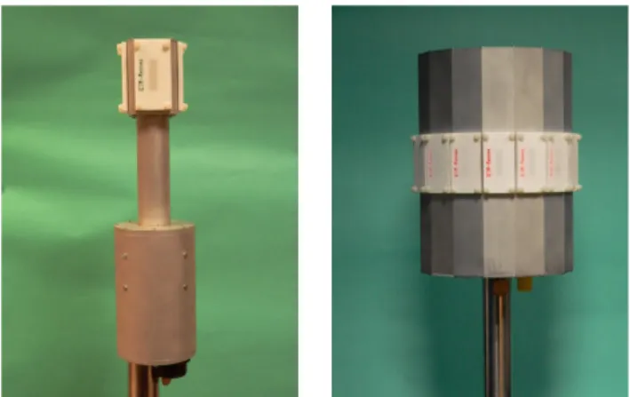
Two UCAs (Uniform Circular Array) were developed at 3.5 GHz (Fig. 1) to characterize 360° azimuthal double directional channel at both link sides. The arrays used contain 4 active elements at the transmitter (Tx) and 16 at the receiver (Rx). At the transmitter we integrated power amplifiers to increase transmitted power, and at the receiver we added LNAs (Low Noise Amplifier) behind the antennas to improve the dynamic of our measurement system. Fig. 2 shows a horizontal cut of the measured beam patterns for the two UCAs.
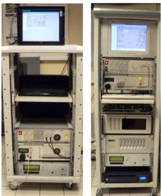
The collected channel data are stored on a laptop for post-processing. Fig. 3 presents the MIMO channel sounder transmitter and receiver.
-2005 -150 -100 -50 0 50 100 150 200 10 15 20 25 30 35 40 Array Orientation [°] M e asur ed M a gni tu de [d B ] -200-180-160-140-120-100 -80 -60 -40 -20 0 20 40 60 80 100 120 140 160 180 200 -40 -30 -20 -10 0 10 20 30 Array Orientation [°] M a gni tude [d B ] ant1 ant2 ant3 ant4 ant5 ant6 ant7 ant8 ant9 ant10 ant11 ant12 ant13 ant14 ant15 ant16
Fig. 2. Antenna measured beam patterns: 4-elements Tx (top) and 16 elements Rx (bottom) .
Fig. 3. MIMO channel sounder: Transmitter (left) and receiver (right).
III. CHANNEL MEASUREMENTS SETUP AND RESULTS
This indoor measurement campaign was conducted in the CLE (Centre de Loisirs Educatifs) building at the INSA of Rennes campus. The transmitter was placed in two positions Tx1 and Tx2 for one fixed position of the receiver Rx. The two measurement configurations were in NLOS (Non Line-Of-Sight) conditions. Fig. 4 presents the layout of the CLE building with the positions of the transmitter and receiver in the building. Fig. 5 shows the transmitter in the position Tx1 where the transmitter antenna height is 2 m. Fig. 6 presents the receiver position in the CLE where the receiving antenna height is 1.3 m.
We assume a quasi-stationary channel during the measurements. Attention was paid that no people were moving in the building during the measurements. For each position, several measurements were taken in order to check stationarity and to average the measurements to reduce the noise floor.
The multipath parameters are obtained by using the high resolution SAGE algorithm [5]. To interpret the measurement results, a ray tracing tool developed by SIRADEL is used [6], [7]. The ray tracing method calculates the possible propagation paths between a transmitter and a receiver. It requires an accurate geometrical description of the considered measurement configuration scene containing the building structure and the position of the partition walls, the floors, the ceilings, the windows and the doors.
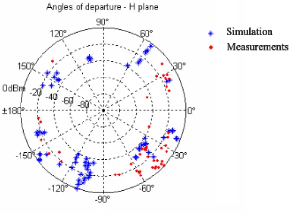
We gave a special attention to the AoD (Angles of Departure) and AoA (Angles of Arrival) which are the most important parameters to evaluate the MIMO systems performance. Fig. 7 shows the angular response (AoD) in the horizontal plane at the transmitter for the position Tx1. The measurement results are presented with red points and simulation results in blue. In this configuration, we observe a large number of multipath in all the directions with an important angular dispersion. We notice also some main propagation directions highlighted with the green arrows. Fig. 8 shows the angular response (AoA) in the horizontal plane at the receiver Rx for the position Tx1. The measurement results are presented with red points and simulation results in blue. We also observe a large number of multipath in all the directions, and also some main propagation directions are highlighted with the green arrows. Fig. 9 presents a comparison between simulation and measurement results where the main directions of departure and arrival are highlighted with green arrows.
Fig. 10 shows the angular response (AoD) in the horizontal plane at the transmitter for the position Tx2. The measurement results are presented with red points and simulation results in blue. Fig. 11 shows the angular response (AoA) in the horizontal plane at the receiver Rx for the position Tx2. The measurement results are presented with red points and simulation results in blue. Fig. 12 presents a comparison between simulation and measurement results. In this configuration, we also observe a large number of multipath in all the directions with a larger angular dispersion then the position Tx1.
The ray tracing permits the interpretation of the measurement results and shows the possible origins of the
multipath in this harsh indoor environment. Some discrepancy between the measured and simulated results is observed. As an example, in Fig. 8, the main propagation direction at -120° is not obtained in the simulation. This can be explained by the reflection and diffraction on the near surrounding buildings, and the furniture in the CLE building that is not considered in the ray tracing simulations.
Tx_2
Tx_1 Rx
Fig. 4. Layout of the CLE building.
Fig. 5. Tx1 location in the CLE building.
Fig. 6. Rx location in the CLE building.
Measurements Simulation
Fig. 7. SAGE estimated AoDs and simulation results for Tx1 position.
Measurements Simulation
Fig. 8. SAGE estimated AoAs and simulation results for Tx1 position.
Measurements Simulation Measurements Simulation Measurements Simulation Measurements Simulation
Fig. 10. SAGE estimated AoDs and simulation results for Tx2 position.
Measurements Simulation Measurements Simulation Measurements Simulation Measurements Simulation
Fig. 11. SAGE estimated AoAs and simulation results for Tx2 position.
Fig. 12. Ray tracing and measurement results for Tx2 and Rx.
IV. CONCLUSION
This paper reports double directional channel measurement campaign conducted in an indoor environment. Multipath parameters are obtained using a high resolution algorithm. A comparison between measurement and simulation results from a ray tracing tool is achieved. The results show a rich scattering environment with a large number of multipath and an important angular dispersion. The future work is to obtain a realistic channel model from these measurement results. Different steps are needed to obtain this channel model. First, since we have a rich indoor scattering environment, we will use a clustering algorithm to model the multiple paths in clusters. Then, statistical values for the multipath parameters like delays, AoDs and AoAs can be deduced from the measurements.
REFERENCES
[1] M. Steinbauer, A. F. Molisch and E. Bonek, “The double-directional radio channel,” IEEE Ant. and Propag. Mag., August 2001, pp. 51–63. [2] E. Bonek, “MIMO propagation channel modeling,” Proc. The EuCAP
Conf., Gothenburg, Sweden, April 2013, pp. 2488-2492.
[3] C. L. Patane, A. Skarbratt, and C. Ornelius, “Basic and advanced MIMO OTA testing of wireless devices using reverberation chamber,” Proc. The EuCAP Conf., The Hague, The Netherlands, April 2014, pp. 3488-3492.
[4] H. Farhat, R. Cosquer, G. Grunfelder, L. Le Coq and G. El Zein, “A dual band MIMO channel sounder at 2.2 and 3.5 GHz,” Proc. of the IEEE I2MTC Conf., Victoria, Vancouver Island, May 2008, pp. 1980–1985. [5] B. H. Fleury, M. Tschudin, R. Heddergott, D. Dahlhaus and K. I.
Pedersen, “Channel parameter estimation in mobile radio environments using the SAGE algorithm,” IEEE J. S. A. C., 1999, 17, pp. 434–450. [6] Y. Lostanlen, G. Gougeon, Y. Corre, "A deterministic indoor UWB
space-variant multipath radio channel modelling", in UWB-SP, vol. 7 ed. F. Sabath & E. Mokole, 2007.
[7] Y. Lostanlen, Y. Corre, "A solution to predict the 3d indoor propagation for future wireless mobile communication systems.", in Proc. PIERS