HAL Id: hal-01121850
https://hal.archives-ouvertes.fr/hal-01121850
Submitted on 3 Mar 2015
HAL is a multi-disciplinary open access
archive for the deposit and dissemination of
sci-entific research documents, whether they are
pub-lished or not. The documents may come from
teaching and research institutions in France or
abroad, or from public or private research centers.
L’archive ouverte pluridisciplinaire HAL, est
destinée au dépôt et à la diffusion de documents
scientifiques de niveau recherche, publiés ou non,
émanant des établissements d’enseignement et de
recherche français ou étrangers, des laboratoires
publics ou privés.
Unit-cell for dual-circular polarisation reflectarrays
S Mener, R Gillard, R Sauleau, A Bellion, P Potier
To cite this version:
S Mener, R Gillard, R Sauleau, A Bellion, P Potier. Unit-cell for dual-circular polarisation
reflectar-rays. 8th European Conference on Antennas and Propagation (EuCAP 2014), Apr 2014, The Hague,
France. pp.1615-1618, �10.1109/EuCAP.2014.6902095�. �hal-01121850�
Unit-cell for dual-circular polarisation reflectarrays
S. Mener
1, R. Gillard
1, R. Sauleau
2, A. Bellion
3, P. Potier
41
: European University of Brittany, INSA, IETR, UMR CNRS 6164, 35708 Rennes, [email protected], [email protected]
2
: University of Rennes 1, IETR, UMR CNRS 6164, 35042 Rennes, [email protected]
3
: CNES, 31401, Toulouse CEDEX 9, France, [email protected]
4
: DGA Maîtrise de l’information, BP 57419, 35174, Bruz CEDEX, France, [email protected]
Abstract—A new unit-cell composed of two layers for dual-CP reflectarrays is proposed for the first time with the unique capability to reflect independently and simultaneously the two incident circular polarisations at the same frequency. The experimental results demonstrate that this unit-cell exhibits a 3.8% bandwidth around 8.4 GHz for a phase resolution better than 1.92 bits in LHCP and in RHCP. As a first step towards a reflectarray in dual-CP, this innovative unit-cell is studied in an array configuration. To increase the value of the maximum incidence angle up to 30°, a matching dielectric layer is placed over the cell.
Index Terms—reflectarray, dual-circular polarisation, circular polarisation selective surface, unit-cell
I. INTRODUCTION
Reconfigurable reflectarrays are very attractive for beam scanning or beam-shaping in space applications such as Earth observations and satellite communications. In order to achieve higher data rate transmissions and prevent from losses due to polarisation misalignment, circular polarisation (CP) is usually preferred. Several circularly-polarised reflectarray unit-cells in frozen states have been proposed in the literature [1], [2], but they only operate with one single CP wave. To our best knowledge, dual-CP unit-cells with independent control of the reflected phases in both polarisations at the same frequency have never been reported so far.
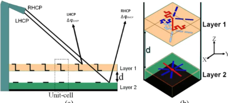
A unit-cell based on a circular polarisation selective surface (CPSS) has been described in [3]-[5] as an attractive building block for dual-CP reconfigurable reflectarrays (Fig. 1a). The proposed unit-cell is made of two layers. The first layer (layer 1 in Fig. 1) is described in detail in [3] and is a Left-Hand CPSS (LH-CPSS) reflecting the incident LHCP with a controllable reflection phase; the incident RHCP is transmitted to the second layer (layer 2 in Fig. 1) that reflects it with an independent controllable reflection phase shift. As layer 2 operates in single polarisation, it only requires standard CP unit-cells (e.g. [6]).
The LH-CPSS has been validated experimentally in [3] and is derived from the Pierrot’s cell [7]. This unit-cell provides a high isolation (20dB at 8.5 GHz) between the two incident circular polarisations and almost a 2-bit phase resolution [3]-[5].
Here, we firstly focus our attention on the whole unit-cell. A convenient co-design of both layers and an optimisation of
the distance d (Fig. 1b) separating them has thus been carried out to obtain simultaneously i) a good isolation between both polarisations, and ii) a 2-bit phase resolution in LHCP and RHCP. Secondly, in Section III, this whole unit-cell is studied in an array configuration to estimate the maximum acceptable incidence angle.
(a) (b)
Fig. 1. (a) Schematic representation of a future reflectarray with independent control of both incident circular polarisations. (b) Unit-cell with dual circular polarisation control.
II. DUAL-CIRCULARLY POLARISED UNIT-CELL
A. Experimental validation of the second layer
As illustrated in Fig. 1, the second layer reflects the incident RHCP wave transmitted through the first layer (LH-CPSS). It is well known that, for an incident CP wave, the reflected phase can be tuned by varying the angular rotation of the reflecting element [8].
This principle has been implemented here around 8.5 GHz: 4 dipoles (Fig. 2) with an appropriate angle of rotation have been defined to reflect the RHCP incident wave with a nearly 2-bit phase resolution. As shown in Fig. 2, each configuration consists of one continuous dipole (in red in Fig. 2) and three non-connected dipoles (in blue in Fig. 2). Each continuous dipole is optimised to reflect totally the parallel component of the incident field while the orthogonal component is reflected by the ground plane. Fig. 2 represents the optimal geometry for the four states of the optimised cell. The main parameters to achieve the optimal geometry are h,
W and L. The four corresponding values of the rotation angles
are the following: -45° for State 2 (90° phase shift), -90° for State 3 (180° phase shift), and -135° for State 4 (270° phase shift). Four breadboards, one per phase state, have been manufactured. The experimental results (not shown)
The authors thank CNES (Centre National d’Etudes Spatiales) and DGA (Direction Générale de l’Armement) for their financial support
demonstrate that the RHCP incident wave is correctly reflected with insertion loss lower than 1 dB over the [8.2-8.8 GHz] range. Moreover, four 90°-spaced phase states are obtained with the same frequency dispersion.
(a) State 1 (b) State 2
(c) State 3 (d) State 4
Fig. 2. Optimised states of the second layer of the unit-cell. L=16.6mm,
w=1mm, h=6.5mm.
B. Experimental results of the dual circularly polarised unit-cell
Layers 1 and 2 have been studied separately in [1] and in Section II.A respectively. They are now combined to form a complete unit-cell for dual-CP reflectarray applications. The sixteen possible configurations and the expected LHCP and RHCP reflected phases are summarized in Table I.
TABLEI
CHARACTERISTICS OF THE 16 CONFIGURATIONS OF THE WHOLE UNIT-CELL
Configuration Layer 1 (LH-CPSS) in state i (1<i<4) Layer 2 (dipole) in state j (1<j<4) Expected LHCP reflected phase at resonance Expected RHCP reflected phase at resonance 1 State 1 State 1 0° 0° 2 State 1 State 2 0° 90° 3 State 1 State 3 0° 180° 4 State 1 State 4 0° 270° 5 State 2 State 1 90° 0° 6 State 2 State 2 90° 90° 7 State 2 State 3 90° 180° 8 State 2 State 4 90° 270° 9 State 3 State 1 180° 0° 10 State 3 State 2 180° 90° 11 State 3 State 3 180° 180° 12 State 3 State 4 180° 270° 13 State 4 State 1 270° 0° 14 State 4 State 2 270° 90° 15 State 4 State 3 270° 180° 16 State 4 State 4 270° 270°
From [3], it can be seen that polarisation isolation of the LH-CPSS cell, although very good, is not perfect: approximately 3% of the power is not properly handled (the isolation coefficients ΓR-L, ΓL-R, TR-L are around 15 dB at 8.5
GHz). As a result, parasitic uncontrolled waves with inappropriate polarisation may arise, thus disturbing the ideal operation described in Fig. 1. Fig. 3 represents the bandwidth of the whole unit-cell for several values of d which is the more prominent degree of freedom to minimize undesirable wave recombination. The optimal distance d is 20mm. Fig. 4
shows a 3D view of the fabricated prototype in configuration 5 (Table I).
Fig. 3. Bandwidth of the whole unit-cell versus d.
Fig. 4. One of the sixteen configurations of the complete unit-cell (here configuration 5).
The amplitudes of the measured reflection coefficients for the sixteen configurations are represented in LHCP and RHCP in Figs. 5a and 5b, respectively.
(a)
(b)
Fig. 5. Measured magnitude of the reflection coefficients for the 16 configurations of the complete unit-cell. (a) LHCP. (b) RHCP.
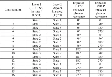
The complete unit-cell exhibits very attractive performances, with a 3.8% fractional bandwidth for insertion loss lower than 1dB in both polarisations. Fig. 6 represents the measured reflected phase for the 16 configurations of the
complete unit-cell, in LHCP (Fig. 6a) and in RHCP (Fig. 6b). Four 90°-spaced phase responses are obtained in reflection with almost the same frequency dispersion in LHCP and in RHCP, respectively for the four states of the first and second layers. Moreover, the phase states in one polarisation do not depend on the phase states of the other polarisation. The simulated and measured equivalent bit numbers are better than 1.92 bits over the [8.2-8.55 GHz] range for both incident polarisations.
(a)
(b)
Fig. 6. Measured phase of the reflection coefficients for the 16 configurations of the complete unit-cell. (a) LHCP. (b) RHCP.
III. STUDY OF THE UNIT-CELL IN A ARRAY CONFIGURATION
In the previous section, the unit-cell was studied in a waveguide simulator. Here the effect of incidence is studied using a more realistic configuration. As represented in Fig. 7, the unit-cell is embedded in a metallic cavity, and a metallic grid extends the cavity above the cell (height hw).
Fig. 7. Schematic representation of the square metallic cavity. The four edges of the cell are PEC walls forming a metallic cavity: ww=0.1mm, hw=20mm.
It is well know that Pierrot’s cell [7] is very sensitive to incidence angle. For our configuration, the dependency to incidence angle is mainly governed by the reflection at the
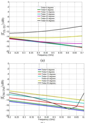
waveguide mouth. To clarify this, the reflection coefficients for incident TE and TM modes on the mouth of a matched waveguide (same section as the metallic cavity containing our cell) have been computed for various incidence angles θ (with
φ=0°). They are represented in Fig. 8. This study demonstrates
that the incidence angle should be limited to θ=20° (for |Γ TE-TE| and |ΓTM-TM| <-10 dB). Note that total reflection at the
waveguide mouth (e.g; for θ=30° and TM mode at 8.4 GHz, Fig. 8b) is caused by scan blindness, as for infinite phased arrays [9], [10].
(a)
(b) Fig. 8. Simulated reflection coefficient at the waveguide mouth for various
incidence angle θ (for φ=0°). (a): TE mode. (b) : TM mode.
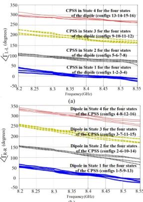
To shift the blind angle and thus increase the value of the maximum incidence angle, a matching dielectric layer has been placed over the cell so as to modify the surface impedance. Its dielectric permittivity is 1.65 and its thickness is 12mm (6mm above the waveguide interface, and 6mm inside, see Fig. 9). Fig. 10 represents the reflection coefficients for the incident TE and TM modes on the waveguide mouth for various incidence angles θ (for φ=0°).
Fig. 9. Schematic representation of the square metallic waveguide with the matching dielectric layer. hw=20mm, hd=12mm.
This study demonstrates that the incidence angle should be now limited to θ=30° (for |ΓTE-TE| and |ΓTM-TM| <-10 dB). Thus,
the maximum acceptable angle of incidence has been increased by 10 degrees.
(a)
(b)
Fig. 10. Simulated reflection coefficients at the waveguide mouth for various incidence angles θ (for φ=0°). (a): TE mode. (b) : TM mode.
The performance of the whole unit-cell (including the cavity and its matching layer) has then been simulated for various incidence angles. The LHCP and RHCP incident waves are correctly reflected with loss lower than 1 dB over the full bandwidth, and the reflected phase for all configurations in LHCP and in RHCP are represented in Fig. 11 for the most critical case (θ=30° and φ=0°). This figure shows that, even in a quite critical configuration (θ=30° and
φ=0°), the phase difference between two consecutive states is
preserved over a large frequency bandwidth. Indeed, four 90°-spaced phase responses are obtained in reflection with almost the same frequency dispersion in LHCP and in RHCP, respectively for the four states of the first and second layers.
(a)
(b)
Fig. 11. Simulated phase of the reflection coefficients for all configurations of the complete unit-cell for θ=30° and φ=0°. (a) LHCP. (b) RHCP.
IV. CONCLUSION
A unit-cell for dual-CP reflectarrays has been proposed for the first time with the unique capability to reflect independently and simultaneously the two incident circular polarisations at the same frequency. The experimental results demonstrate that this unit-cell exhibits a 3.8% bandwidth for a phase resolution better than 1.92 bits in LHCP and in RHCP. Then, as a first step towards a reflectarray in dual-CP, this innovative unit-cell has been studied in an array configuration. To increase the value of the maximum incidence angle up to 30°, a matching dielectric layer has been placed over the cell.
REFERENCES
[1] J. H. Wang, “Characteristics of a new class of diode-switched integrated antenna phase shifter,” IEEE Trans. Antennas Propag, vol. 31, no. 1, pp. 156-159, Jan. 1983.
[2] E. Martynyuk, J. I. Martinez Lopez, and N. A. Martynyuk, “Reflectarray based on three bit spatial phase shifters: mathematical model and technology of fabrication,” Proceedings of the 3rd European
Conference Antennas and Propag., Berlin, Germany, 23-27 Mar. 2009.
[3] S. Mener, R. Gillard, R. Sauleau, C. Cheymol, and P. Potier, “Design and characterization of a CPSS-based unit-cell for circularly-polarized reflectarray applications,” IEEE Trans. Antennas Propag, vol. 61, no. 4, pp. 2313-2318, Apr. 2013.
[4] S. Mener, R. Gillard, R. Sauleau, C. Cheymol, and P. Potier, “A CPSS-based reflectarray cell with reconfigurable capabilities,” Proceedings of
the 6th European Conference Antennas and Propag., Prague, Czech
Republic, 26-30 Mar. 2012.
[5] S. Mener, R. Gillard, R. Sauleau, C. Cheymol, and P. Potier, “Design of a CPSS-based reflectarray cell with controllable reflected phase for dual circularly polarized reflectarrays,” Proceedings of the Intern. Symp. on
Antenna Technology and Applied Electromagnetics, ANTEM 2012,
Toulouse, France, 25-28 Jun. 2012.
[6] E. Girard, R. Moulinet, R. Gillard and H. Legay, “An FDTD optimization of a circularly polarized reflectarray unit cell,” IEEE
Antennas Propag. Soc. Int. Symposium, San Antonio (TX), vol. 3, pp.
136-139, Jun. 2002.
[7] R. Pierrot, “Éléments résonnants en polarisation circulaire et réflecteur semi-transparent composé de ces éléments,” French patent 89.609, no. 1.512.598, 1966.
[8] J. Huang and R. J. Pogorzelski, “A Ka-band microstrip reflectarray with elements having variable rotation angles,” IEEE Trans. Antennas
Propag, vol. 46, no. 5, pp. 650-656, May 1998.
[9] D. M. Pozar and D. H. Schaubert, “Scan Blindness in Infinite Phased Arrays of printed Dipoles,” IEEE Trans. Antennas Propag., vol. 32, no. 6, pp. 602-610, Jun. 1984.
[10] B. Sanadgol, O. Litschke and K. Solbach, “Method to predict scan blindness in printed planar phased arrays,” Proceedings of the 3rd
European Conference Antennas and Propag., Berlin, Germany, 23-27