HAL Id: tel-02003520
https://tel.archives-ouvertes.fr/tel-02003520
Submitted on 1 Feb 2019HAL is a multi-disciplinary open access archive for the deposit and dissemination of sci-entific research documents, whether they are pub-lished or not. The documents may come from teaching and research institutions in France or
L’archive ouverte pluridisciplinaire HAL, est destinée au dépôt et à la diffusion de documents scientifiques de niveau recherche, publiés ou non, émanant des établissements d’enseignement et de recherche français ou étrangers, des laboratoires
cutaneous devices based on organic materials for human
electrophysiological recordings
Thomas Lonjaret
To cite this version:
Thomas Lonjaret. Micro-fabrication of wearable and high-performing cutaneous devices based on organic materials for human electrophysiological recordings. Other. Université de Lyon, 2016. English. �NNT : 2016LYSEM021�. �tel-02003520�
N°d’ordre NNT : 2016LYSEM021
THESE de DOCTORAT DE L’UNIVERSITE DE LYON
opérée au sein de
l’Ecole des Mines de Saint-Etienne
Ecole Doctorale
N° 488
Sciences, Ingénierie, Santé
Spécialité de doctorat
: MicroélectroniqueDiscipline
: BioélectroniqueSoutenue à huis clos le 25/10/2016, par :
Thomas Edouard Lonjaret
Micro-fabrication of wearable and
high-performing cutaneous devices based on
organic materials for human
electrophysiological recordings
Devant le jury composé de :
- - - Président du Jury
Salleo Alberto Professeur associé Stanford University Rapporteur Lacour Stéphanie Professeur Ecole Polytechnique Fédérale de Lausanne Rapporteure Yvert Blaise Directeur de Recherche INSERM Examinateur Badier Jean-Michel Ingénieur de Recherche Aix-Marseille Université Examinateur Malliaras George Professeur Ecole des Mines de Saint-Etienne Directeur de thèse Ismailova Esma Ingénieure de recherche Ecole des Mines de Saint-Etienne Co-encadrante de thèse Fiocchi Michel Directeur de l'entrepreunariat Ecole des Mines de Saint-Etienne Co-encadrant de thèse Hervé Thierry C.E.O Microvitae Technologie Invité
ABSI Nabil CR Génie industriel CMP AUGUSTO Vincent CR Image, Vision, Signal CIS AVRIL Stéphane PR2 Mécanique et ingénierie CIS BADEL Pierre MA(MDC) Mécanique et ingénierie CIS BALBO Flavien PR2 Informatique FAYOL BASSEREAU Jean-François PR Sciences et génie des matériaux SMS BATTON-HUBERT Mireille PR2 Sciences et génie de l'environnement FAYOL
BEIGBEDER Michel MA(MDC) Informatique FAYOL BLAYAC Sylvain MA(MDC) Microélectronique CMP BOISSIER Olivier PR1 Informatique FAYOL BONNEFOY Olivier MA(MDC) Génie des Procédés SPIN
BORBELY Andras MR(DR2) Sciences et génie des matériaux SMS BOUCHER Xavier PR2 Génie Industriel FAYOL BRODHAG Christian DR Sciences et génie de l'environnement FAYOL BRUCHON Julien MA(MDC) Mécanique et ingénierie SMS
BURLAT Patrick PR1 Génie Industriel FAYOL CHRISTIEN Frédéric PR Science et génie des matériaux SMS DAUZERE-PERES Stéphane PR1 Génie Industriel CMP DEBAYLE Johan CR Image Vision Signal CIS DELAFOSSE David PR0 Sciences et génie des matériaux SMS DELORME Xavier MA(MDC) Génie industriel FAYOL DESRAYAUD Christophe PR1 Mécanique et ingénierie SMS
DJENIZIAN Thierry PR Science et génie des matériaux CMP DOUCE Sandrine PR2 Sciences de gestion FAYOL DRAPIER Sylvain PR1 Mécanique et ingénierie SMS FAVERGEON Loïc CR Génie des Procédés SPIN FEILLET Dominique PR1 Génie Industriel CMP FOREST Valérie MA(MDC) Génie des Procédés CIS FOURNIER Jacques Ingénieur chercheur CEA Microélectronique CMP FRACZKIEWICZ Anna DR Sciences et génie des matériaux SMS GARCIA Daniel MR(DR2) Génie des Procédés SPIN GAVET Yann MA(MDC) Image Vision Signal CIS GERINGER Jean MA(MDC) Sciences et génie des matériaux CIS GOEURIOT Dominique DR Sciences et génie des matériaux SMS GONDRAN Natacha MA(MDC) Sciences et génie de l'environnement FAYOL GRAILLOT Didier DR Sciences et génie de l'environnement SPIN GROSSEAU Philippe DR Génie des Procédés SPIN GRUY Frédéric PR1 Génie des Procédés SPIN GUY Bernard DR Sciences de la Terre SPIN HAN Woo-Suck MR Mécanique et ingénierie SMS HERRI Jean Michel PR1 Génie des Procédés SPIN KERMOUCHE Guillaume PR2 Mécanique et Ingénierie SMS KLOCKER Helmut DR Sciences et génie des matériaux SMS LAFOREST Valérie MR(DR2) Sciences et génie de l'environnement FAYOL
LERICHE Rodolphe CR Mécanique et ingénierie FAYOL MALLIARAS Georges PR1 Microélectronique CMP MOLIMARD Jérôme PR2 Mécanique et ingénierie CIS MOUTTE Jacques CR Génie des Procédés SPIN NIKOLOVSKI Jean-Pierre Ingénieur de recherche Mécanique et ingénierie CMP NORTIER Patrice PR1 SPIN OWENS Rosin MA(MDC) Microélectronique CMP PERES Véronique MR Génie des Procédés SPIN PICARD Gauthier MA(MDC) Informatique FAYOL PIJOLAT Christophe PR0 Génie des Procédés SPIN PIJOLAT Michèle PR1 Génie des Procédés SPIN PINOLI Jean Charles PR0 Image Vision Signal CIS POURCHEZ Jérémy MR Génie des Procédés CIS ROBISSON Bruno Ingénieur de recherche Microélectronique CMP ROUSSY Agnès MA(MDC) Génie industriel CMP ROUSTANT Olivier MA(MDC) Mathématiques appliquées FAYOL
STOLARZ Jacques CR Sciences et génie des matériaux SMS TRIA Assia Ingénieur de recherche Microélectronique CMP VALDIVIESO François PR2 Sciences et génie des matériaux SMS VIRICELLE Jean Paul DR Génie des Procédés SPIN WOLSKI Krzystof DR Sciences et génie des matériaux SMS XIE Xiaolan PR1 Génie industriel CIS YUGMA Gallian CR Génie industriel CMP
EMSE : Enseignants-chercheurs et chercheurs autorisés à diriger des thèses de doctorat (titulaires d’un doctorat d’État ou d’une HDR)
GENIE DES PROCEDES F. Gruy, Maître de recherche SCIENCES DE LA TERRE B. Guy, Directeur de recherche SCIENCES ET GENIE DE L’ENVIRONNEMENT D. Graillot, Directeur de recherche
IMAGE, VISION, SIGNAL JC. Pinoli, Professeur GENIE INDUSTRIEL X. Delorme, Maître assistant MICROELECTRONIQUE Ph. Lalevée, Professeur
M ise à jo ur : 01/02/ 2016
Acknowledgements
Most of this work was carried out South of France, in the city of Gardanne, at the Department of Bioelectronics (BEL), part of the Microelectronics Center of Provence (CMP), research institute of the engineering school École Nationale Supérieure des Mines de Saint-Etienne. A lot of names to define a place where I spent most of the three years of my PhD, a place a modern research center tries to emerge from, between last century industry and wonderful surrounding forests and mountains. . . From my office I could see the Sainte-Victoire mountain, next to which the company I was part of, Microvitae Technologie, is located. Integrated as a research engineer, I discovered there the exciting world of startups and everything about medical devices.
But all of the following work would have been nothing without my colleagues, who became my friends. I will always remember the long and fruitful discussions we had (yes, about science and work, but not only), our volleyball games on Marseille’s beach, hikes in the Calanques, beers in Tibbar, trips for often unsuccessful experiments in La Timone, collaborations in clean room, gossips about everything, holidays after conferences. . .
First, I would like to thank my advisors and scientists from BEL. George, you are a giant, and I hope that, one day, I will be able to walk in your footsteps while staying as confident and optimist as you always are. Esma, you are a wonderful person, I am sure the textile team you built up from scratch has a promising future. It was a pleasure to work with you and we had a lot of fun in Arizona. I hope I was not too terrible as your first PhD student! Michel, you are the network guy who did everything in his life, thank you for your wise advices and help. Roisin, it will always be a pleasure to discuss with you and to discover how efficent you are. I will not forget that you are the only one able to put the lab in order with a smile! Adel, tireless bike rider, we still have to talk about a lot of stuff, including the dinosaurs (I did not forget!). I really enjoyed the time I spent and giggles I had with people from the CMP, such as Thierry, Michele, Gracien, Florent, Stéphane, Bernard, Béné, Catherine, François, Hervé... I am certainly forgetting too many other people... And what to say about PhD students and postdocs from Bel, these amazing guys coming from all around the world? Many people passed by the lab and were more or less associated with my work: Xenofon, Marc, Adam, Wonryung, Bartek, Jake, Bastien, Aimie. . . But some names will be forever associated with my work at BEL. The crazy, manic, so-German, but efficient and funny Marcel, who will be strong and muscular, one day. The lazy but tireless and tenacious Ilke, who will be an expert in electronics and soldering, soon. The loquacious, gossipy and ink-jet printing-lover Eloïse,
who was my officemate and my companion of adventure and misfortune. The smiling Jolien, always over-excited for everything, who is snowboarding as good as she speaks French (until the bump!). The pretty and LabVIEW-expert Anna-Maria, who will never forget how to turn on a computer. The clean-room-lover, stubborn but friendly Dimitrios/is/i, who will think that, of course, this thesis is about Greek history. The member of high-society, athletic only for tennis, and Goethe-lover Shahab, who may dare start to learn le français vulgaire de la rue, one day. The discrete Mahmoudhy, who may coat his skis with GOPS, to avoid falling on the snow. The cell-lover, industrious and early bird Magali, who finally replaced me as youngest PhD student to cut Galette des Rois. The briton, Loig, who may bet with Roisin another office and a bigger desk by playing jeux de palets. The enthusiastic Carol, the perpetual student who should start to kiss her probes every morning to say hello, the may become less jealous and start to work! The proud and so-Sicilian Vincenzo, who may open a micro-fluidic soap fabrication plant after postdoc. The mysterious Paschalis, who is the only one able to know what the neuromorphic devices are for. The hiker, flirty, sometimes scientific Chris, who will be able to correctly say the French rrr, one day. The sporty and rasta Mary, who is trying to walk barefoot in the lab as soon as Adel is not around. The naive but never mean Yi, who is actually a secret fan of Dalaï-Lama. The ingenious Ussein, knonw as the Brother, who come to work just to have the pleasure to taste his pilaf rice. Ilke’s mamma, Sahika, who chose petrol instead of never-ending post-doc positions. The kind and muscular Babis, whose actual name is unpronounceable and who is just happy of having every day his lunched cooked by Anna-Maria. I need to finish this list with Pierre, who was kind of my mentor when I started, to finish as my driver for bakery in the last months. I will not forget people from Microvitae, Valéry, Timothée. We stayed together through difficulties but I also enjoyed our chats to change the world!
Special thanks to Lucie, my girlfriend who became my wife during this PhD, for her kind advices and support, even if she still does not know what is PEDOT after hearing this word hundreds of times! To my parents who gave me the chance to become a doctor! To my brother and sister just because I love them!
Résumé
L’ensemble du corps humain est surveillé par différents capteurs médicaux connectés, que ce soit depuis une montre connecté ou par un pacemaker. Ces capteurs permettent une nette amélioration du suivi de notre santé, à l’hôpital, mais surtout dans notre vie de tous les jours, notamment en enregistrant les signaux électrophysiologiques. L’électrophysiologie consiste à étudier les signaux électriques et électrochimiques générés aussi bien par certaines cellules spécifiques que par des organes entiers. Elle donne donc aux médecins l’opportunité de suivre le fonctionnement du corps à plusieurs échelles. L’enregistrement de ces activités par des électrodes est essentiel pour le diagnostic et la compréhension de pathologies aussi diverses que les arythmies cardiaques, l’épilepsie ou la dégénération musculaire. Dans cette thèse, nous étudions différents types d’électrodes cutanées à base de matériaux organiques, de leur conception à leur évaluation préclinique. Le principal but de ce travail est de dévelop-per une interface souple et compatible avec la peau humaine, afin de réaliser des mesures électrophysiologiques performantes.
Notre approche est basée sur l’utilisation du polymère conducteur PEDOT :PSS et de gels ioniques, qui réduisent l’impédance de l’interface électrode-peau. Différents substrats fins et souples, plastiques ou textiles, composent nos électrodes. Cela leur confère une impor-tante flexibilité et permet même de les intégrer à des vêtements. De nouvelles techniques de fabrications, adaptées à ces substrats et aux matériaux organiques, sont présentées. Afin de démontrer les excellentes performances de nos capteurs innovants par rapport aux électrodes médicales usuelles, ceux-ci sont intégralement caractérisés, puis testés sur des volontaires. L’enregistrement de signaux cutanés issus des tissus musculaires, cardiaques et cérébraux permet d’évaluer la stabilité sur plusieurs jours et la qualité de nos électrodes. Nous introdui-sons également le transistor organique électrochimique, utilisé pour la première fois comme une électrode cutanée microscopique dite « active ». Celui-ci permet d’amplifier et de filtrer in situ le signal afin d’augmenter sa qualité. Du fait de leurs forts potentiels industriels et cliniques, nous étudions maintenant l’intégration de nos électrodes organiques cutanées dans des produits médicaux de pointe.
Mots clefs: Dispositif Médical, électrode, électrophysiologie, électronique organique, transis-tor organique électrochimique, capteurs flexibles intégrés
Abstract
In our medicalized world, human-monitoring sensors can be found everywhere, from a smart-watch to a life-saving pacemaker. They facilitate direct recordings of our electrophysiological activity, in the hospital as well as in our everyday life. Electrophysiology is the study of electrical and electrochemical signals generated by specific cells or whole organs. It gives doctors the opportunity to track the physiological behavior of a single neuron, a muscle tissue or the integral brain. The recording of these activities is essential to diagnose and better understand diseases like cardiac arrhythmias, epilepsy, muscular degeneration and many more. In this thesis, we study different types of cutaneous electrodes based on organic materials, from conception to pre-clinical evaluation. The main focus of this work is to enable high-quality electrophysiological recordings through soft and flexible devices compatible with human skin. Our approach is based on the usage of PEDOT:PSS conducting polymer and ionic gels in order to reduce impedance at the skin-electrode interface. Moreover, the substrate of our electrodes is made with different materials such as thin and conformable plastics and textiles. Our devices are then flexible, motion resistant and can be integrating into clothes. We developed new fabrication processes, considering the different substrates and organic materials specifics. The electrodes were characterized and then tested on human volunteers to show their excellent performance in comparison to standard medical electrodes. The evaluation of noise reduction capabilities and possibilities to perform long-term recordings were established on signals coming from muscles, heart and brain. In order to further reduce noise and to increase wearability, we present a hundred micrometer-small “active” electrode, based on the organic electrochemical transistor. It enables in situ amplification and filtering of recorded signals. The wearable organic electrodes developed in this work are of great industrial and clinic interest. Future work will aim to integrate these technologies into state-of-the-art medical devices.
Key words: Medical Device, electrode, electophysiology, organic electronics, organic
Contents
Acknowledgements i
Abstract (Français/English) iii
List of figures xi
Nomenclature xiii
1 Introduction on electrophysiology and medical devices 1
1.1 Overview on electrophysiology . . . 1
1.1.1 Genesis of electric biosignals . . . 1
1.1.2 Different modalities for electrophysiology . . . 4
1.1.3 Overview on the acquisition chain for electrophysiological recordings . 10 1.2 Analysis of medical needs for electrophysiology . . . 12
1.2.1 Electrophysiology to diagnosis pathologies . . . 12
1.2.2 Electrophysiology to assist pathologies . . . 14
1.2.3 Current problematics for ambulatory electrophysiology . . . 15
1.3 Industrial vision for medical devices conception . . . 17
1.3.1 From the idea to the mass production of medical devices . . . 18
1.3.2 How can research and development add value to medical device concep-tion? . . . 19
1.3.3 CE marking . . . 21
1.4 Bibliography . . . 24
2 Electrodes 31 2.1 A model of the electrode and the reactions at its interface . . . 31
2.1.1 Electrochemical model of the electrode . . . 31
2.1.2 Noise generation . . . 33
2.1.3 The electrolyte in electrophysiology . . . 35
2.1.4 Skin specificities for cutaneous electrophysiology . . . 36
2.1.5 Equivalent model of skin-electrode interface . . . 36
2.2 Electrode characterization . . . 37
2.2.1 Three-electrode cell and potentiostat . . . 37
2.2.2 Impedance . . . 38
2.2.3 DC voltage offset measurement . . . 41
2.2.5 Biocompatibility . . . 42
2.3 Medical Electrodes for electrophysiology . . . 43
2.3.1 Options around the conception of an electrode . . . 43
2.3.2 Presentation of different medical electrodes . . . 45
2.4 Bibliography . . . 47
3 Improving skin-electrode interface with conducting organic materials 49 3.1 Introduction on organic electronics . . . 50
3.1.1 Organic materials . . . 50
3.1.2 Conducting polymers . . . 50
3.1.3 Organic bioelectronics . . . 51
3.2 The use of conducting polymers for electrophysiology . . . 53
3.2.1 State-of-the-art on the use of conducting polymers to improve electrode interface . . . 53
3.2.2 Fabrication processes and characterization of dry PEDOT:PSS electrodes 54 3.3 The use of ionic liquids for electrophysiology . . . 56
3.3.1 Introduction on ionic liquids . . . 56
3.3.2 Ion gels as solid electrolytes . . . 57
3.3.3 Synthesis and integration of ion gels on electrodes . . . 58
3.4 Introduction of a novel biocompatible ion gel for electrodes . . . 58
3.4.1 Biocompatibility of cholinium-based ionic liquids . . . 58
3.4.2 Chemical materials . . . 59
3.4.3 Preparation of the ion gel . . . 59
3.4.4 Characterization . . . 60
3.4.5 Discussion . . . 64
3.5 Bibliography . . . 64
4 Organic conductors in wearable sensors 73 4.1 Electrodes on flexible substrates . . . 74
4.1.1 Review of flexible electrodes to monitor internal organs . . . 74
4.1.2 Review of flexible electrodes for cutaneous applications . . . 74
4.1.3 Fabrication of plastic cutaneous electrodes . . . 75
4.1.4 Discussion . . . 77
4.2 Introduction of innovative electrodes based on textile substrate . . . 77
4.2.1 Introduction on textile electronics . . . 77
4.2.2 Coating of PEDOT:PSS and ion gel on knitted textile . . . 79
4.2.3 Characterization of textile electrodes . . . 82
4.2.4 Discussion . . . 85
Contents
5 Cutaneous electrophysiology with organics 93
5.1 Dry electrodes . . . 94
5.1.1 State-of-the-art on dry electrodes . . . 94
5.1.2 Discussion . . . 95
5.2 Ionic gel-assisted electrodes . . . 95
5.2.1 Experimental . . . 95
5.2.2 Electrode characterization . . . 96
5.2.3 ECG recordings . . . 97
5.2.4 Discussion . . . 98
5.3 Wearable textile electrodes . . . 99
5.3.1 Experimental . . . 99
5.3.2 Electrode characterization on skin . . . 100
5.3.3 ECG recording . . . 101
5.3.4 Discussion . . . 103
5.4 Recording and stimulation performances of textile electrodes . . . 104
5.4.1 Experimental . . . 104
5.4.2 Electrode characterization for stimulation . . . 105
5.4.3 EMG recording and stimulation . . . 105
5.4.4 Discussion . . . 107
5.5 Bibliography . . . 108
6 Potential of OECT for next generation electrophysiology 111 6.1 Introduction on Organic ElectroChemical Transistors . . . 112
6.1.1 Organic transistors . . . 112
6.1.2 The Organic ElectroChemical Transistors . . . 112
6.1.3 Fabrication process . . . 113
6.1.4 Applications of the OECT . . . 116
6.2 OECT as a pre-amplifier for electrophysiological recordings . . . 117
6.2.1 Connection set-up and Characterization . . . 117
6.2.2 Results on ECG . . . 118
6.2.3 Results on EOG . . . 120
6.2.4 Results on EEG . . . 122
6.2.5 Discussion . . . 122
6.3 Enabling the compatibility of OECT technology with medical systems . . . 123
6.3.1 Experimental part . . . 123
6.3.2 Addition of a load resistor . . . 123
6.3.3 Voltage gain in linear and saturation regimes . . . 125
6.3.4 Voltage amplification of ECG signals . . . 127
6.3.5 Discussion . . . 128
6.4 Outlook: Improved OECT in direct contact with skin as active electrodes . . . . 128
6.4.1 OECT and active electrodes . . . 129
6.4.3 Work on going . . . 130 6.5 Bibliography . . . 131
List of Figures
1.1 Anatomy of a neuron and zoom into the cell membrane . . . 2
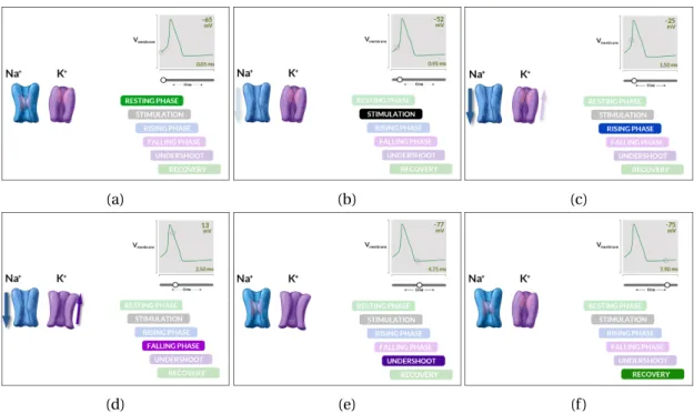
1.2 Generation steps of an action potential . . . 3
1.3 10-20 system for EEG . . . 5
1.4 Technologies to record brain activity . . . 6
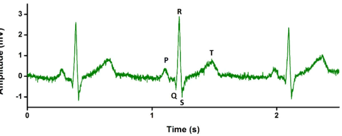
1.5 Standard ECG signal . . . 8
1.6 EMG signal during plantar-flexion contraction . . . 10
1.7 Acquisition chain for clinical electrophysiology . . . 12
1.8 Medical Devices Conception Chain . . . 20
2.1 The Galvanic electrochemical cell . . . 32
2.2 Motion artifacts in ECG signals . . . 35
2.3 Skin layers . . . 36
2.4 Equivalent circuit for the electrode-skin interface . . . 37
2.5 Schematic of a potentiostat system . . . 38
2.6 Example of Electrochemical Impedance Spectroscopy . . . 40
2.7 Example of Cyclic voltammetry measurement . . . 42
2.8 List of options for electrode development . . . 44
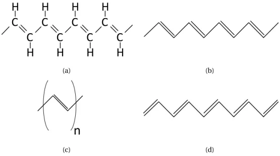
3.1 An example of conducting polymer: trans-poylacetylene . . . . 51
3.2 Chemical structure of PEDOT:PSS . . . 54
3.3 Impedance and CV characterization of PEDOT:PSS elecrodes . . . 56
3.4 1-ethyl-3-methylimidazolium ethyl sulfate ion gel preparation . . . 58
3.5 Cholinium lactate ion gel preparation . . . 60
3.6 Rheological properties of cholinium lactate ion gels . . . 61
3.7 Thermal properties of cholinium lactate ion gels . . . 62
3.8 Electrical properties of cholinium lactate ion gels . . . 63
3.9 Long-term stability of cholinium lactate ion gels and water absoprtion . . . 64
4.1 Laser-cutting of Kapton substrates . . . 76
4.2 Examples of Kapton-based electrodes . . . 77
4.3 Process flow for the patterning of PEDOT:PSS on textile . . . 81
4.4 Examples of PEDOT:PSS-patterned knitted textiles . . . 82
4.5 Integration of ion gel on textile for cutaneous electrodes . . . 83
4.6 Mechanical properties of the textile electrode . . . 84
5.2 Comparison of ECG signals between medical electrode and cholinium ion gel
electrodes . . . 98
5.3 Cholinium-based ion gel electrode evaluation for long-term ECG evaluation . . 98
5.4 Impedance spectra of textile and medical electrodes . . . 100
5.5 Textile electrode evaluation for amublatory ECG monitoring . . . 102
5.6 Textile electrode evaluation for long-term ECG evaluation . . . 103
5.7 Cyclic voltammetric measurement on textile electrode . . . 106
5.8 EMG recording with textile electrode . . . 107
5.9 Performance of conducting polymer textile electrode in muscular stimlulation 108 6.1 Schematic of the OECT . . . 113
6.2 OECT fabrication process with photolithography . . . 115
6.3 Characteristics of low temperature annealed OECTs . . . 116
6.4 Set-up of the OECT as pre-amplifier and caracterization . . . 119
6.5 ECG with OECT as pre-amplifier . . . 120
6.6 EOG with OECT as pre-amplifier . . . 121
6.7 Eye blinking and closing recorded with OECT as pre-amplifier . . . 121
6.8 EEG with OECT as pre-amplifier . . . 122
6.9 Characterization of an OECT with drain load resistor . . . 125
6.10 Experimental data versus model for amplification gain . . . 127
6.11 Amplification of ECG signals in saturation and linear regimes . . . 128
Nomenclature
AC Alternative current
BCI Brain-computerr interface CE Counter electrode
CV Cyclic voltammetry
DBSA Dodecyl benzene sulfonic acid DC Direct current
ECG Electrocardiography or Electrocardiograph or Electrocardiogram ECoG Electrocorticography or Electrocorticograph or Electrocorticogram
EEG Electroencephalography or Electroencephalograph or Electroencephalogram EMG Electromyography or Electromyograph or Electromyogram
EOG Electrooculography or Electrooculograph or Electrooculogram FET Field-effect transistor
GOPs (3-glycidyloxypropyl) trimethoxysilane IL Ionic liquid
LFP Local field potential
MD Medical Device (as defined by the European Medical Devices Directive (93/42/EEC)) MOSFET Metal-oxide-semiconductor field-effect transistor
MU Motor Unit
OECT Organic electrochemical transistor OFET Organic field-effect transistor OLED Organic Light-emitting diode
RE Reference electrode
RTIL Room temperature ionic liquid SEEG Stereoencephalography SNR Signal to noise ratio WE Working electrode
1
Introduction on electrophysiology
and medical devices
To assess a technological challenge, an engineering approach is impossible without taking into account all constraints for the future product. Choices are then somehow limited but the solution will be directly conformable to an industrial production or utilization. A fundamental or academic approach opens more possibilities and give often rise to innovative ideas. All along this PhD, I tried to use both of these approaches (which are somehow complementary) to develop innovative cutaneous recording devices for electrophysiology.
First of all, we need to define the context and the users and technological needs of this challenge, and this is the goal of this first chapter. An overview of the field of electrophysiology, which is the main application of all the work presented in this thesis, will be given in order to show and explain which kind of signals are involved and what are the clinical ways of recording them. Then, a closer look to the daily problems occurring in clinic will be necessary to explore and understand medical needs. Finally, since this work was made with an industrial partner, the last part of this chapter will detail the industrial vision to develop a medical device. In my sense, this industrial point of view has to be taken into account, even for scientists. When developing an idea in the specific field of medical devices, it is important to know from the beginning what could be constraints for a future industrialization.
1.1 Overview on electrophysiology
1.1.1 Genesis of electric biosignals
Presentation of a neuron
The main generator of bioelectric signal is the neuron, presented on Fig 1.1a. A quick descrip-tion of the neuron and its working principle will be presented here. A neuron is made of a cell body, also called soma, which contains the nucleus. The soma presents 2 extensions, the dendrites and the axon. It is possible to find thousands of dendrites branching profusely from one neuron whereas the axon is always single. The axon length varies from a millimeter to more than a meter and it is covered by myelin sheaths. At its end, it gives rise to hundred of branches, ended by synapses (contact area between the axon of a neuron and a dendrite or
soma of another one). Axons are often bundled into fascicles which can make up nerves in the peripheral nervous system.
Neurons are the support for the transmission of information, which is an electric signal called action potential (described more in depth in next Section 1.1.1). Neurons communicate each other mostly by synapses. If a neuron receives a specific amount of post-synaptic potentials from a previous neuron, a new action potential can be generated. It propagates through the axon where its speed can be increased by myelin sheaths. Then this potential is transmitted to the next neurons and so on. Neurons are used both as signal processing units and connection wires to transform and transmit electric signals between central nervous system and peripheral organs.
SOMA AXON
NUCLEUS MYELIN SHEAT SYNAPTIC TERMINAL
(a) (b)
Figure 1.1 – Anatomy of a neuron and zoom on the cell membrane. (a) Drawing of a neuron with highlighted subdivisions. (b) Sectional view of the lipid bilayer neuron membrane separating intra- and extra-cellular medium, a closed potassium and opened sodium ion channels.
Action potential generation
In this section, we focus on the generation of this action potential. At rest, there is a negative potential difference (around −70 mV) across the neuron membrane, between the extracellular and the intracellular medium. This difference results from difference of ions concentrations across the membrane. This membrane is made of a lipid bilayer and contains ion channels, as described in the cartoon Fig 1.1b. Nerve impulses are characterized by an instantaneous mod-ification of membrane permeability through the opening and closing of these ion channels. Fig 1.2 shows the difference steps for the changes of membrane potential at a single point of the membrane. During the resting phase, single-directional potassium (K+) and sodium (N a+) ion channels are closed and a constant potential is kept. The stimulation induced by the upstream propagation of the action potential opens the N a+ion channel which leads to a flow of sodium ions through the cell membrane, increasing the potential difference up to 35 mV. Then K+ion channels open and potassium ions escape the cell to the external media, leading to the depolarization state. N a+ion channels and then K+ion channels close
1.1. Overview on electrophysiology
successively and the potential difference is back to the resting state [1]. Next ion channels were stimulated during the rising phase and the same phenomenon happen. This allows the propagation of the action potential along the membrane. When the action potential reaches the axon terminal, the signal propagates from the neuron to the next one through the synapse. For mammalians, the majority of synapses are chemical. The action potential causes synaptic vesicles to fuse with the membrane and to release their neurotransmitter molecules. These neurotransmitters diffuse and activate receptors on the postsynaptic neuron.
Neurons are not the only cell that can propagate action potentials. Muscle cells, also known as myocytes, can propagate action potentials as well, in the same way as neurons. They are stimulated by nerves and the propagation of an action potential involves their contraction and so the movement of the corresponding muscle (more details on the Section 1.1.2).
(a) (b) (c)
(d) (e) (f )
Figure 1.2 – Generation steps of an action potential. (a) At rest, both ion channels are closed. The potential difference between in and out of the cell is stable, around −65 mV. (b) Sodium channel are stimulated by an upstream current and start to open. (c) Sodium ions penetrate inside the cell layer and increase the membrane potential. (d) A potential peak around 35 mV triggers the opening of the potassium channels. Potassium ions are moving out of the cell, the membrane potential falls back. (e) The membrane potential reaches a low threshold which leads to the closing of sodium channels and then of potassium channels. (f ) During recovery state, both ion channels are closed, membrane potential comes back to its value from resting state and ions channel cannot react to a stimulation.
Propagation in the body
The current generated by a single neuron (a small elementary current dipole) is not measurable from the skin and barely from surrounding electrodes. Signals with high-enough amplitude to be recorded from the skin are generated by a large number of synchronized active neurons and this can be modeled by an equivalent dipole. A spatial organization, that involves current addition, is also needed. This is the case for pyramidal neurons from the cortex which are aligned in a parallel way [2].
An electrophysiological recording is the measurement of the potential difference between 2 points of the body. This potential difference is generated by currents which propagate inside the volume of the body. Main factors of current propagation are the bones (especially the skull), which are less conductive than the brain or the skin. Bones are places where current are attenuated and diffused, which induces a spatial smoothing of electric potentials. In general terms, any modification of the homogeneity of the propagation medium will lightly modify the signal, and this needs to be taken into account for signal processing, especially for EEG.
1.1.2 Different modalities for electrophysiology
Electroencephalography (EEG)
Hans Berger was the first one to use EEG to record electric activity from a human brain, at the end of the 1920s [3]. However, the cerebral origin of these signals had not taken hold right away, and the neurologists started to be interested by EEG after the work of Lord Adrian in the 1930s [4]. Medical and scientific applications of EEG are now remarkably important.
As we explained previously, the opening of ion channels allows ions to move back and forth in the intra- and the extra-cellular medium. When this is happening to a large amount of neurons, an electrical field (local field potential, LFP) is created; and since the extra-cellular medium is conductive, the latter induces a secondary current which circulate in the whole volume of the head. It is important to note that glial cells, surrounding the neurons in the brain, also electroactive, could slightly influence EEG signal by generating small potential variations [5] but this is still under discussion between specialists. Potential variations at the surface of the scalp, produced by the secondary current, are recorded by electrodes placed on the scalp and the resulting signal is called an EEG. Synchrony of LFPs induces typical oscillations within specific frequency domains. The amplitude of this signal is very low (typically 25-100 µV because the scalp, the skull, the cerebrospinal fluid and the meninges are inhomogeneous media which attenuated the signal. An estimation of skull conductivity gives a result 20 to 80 lower than the conductivity of the cerebral fluid and so the skull acts ad low-pass spatial filter [6]. Although strong signal amplification is needed and spatial resolution is low, EEG is a cheap and non-invasive way to record brain activity with a good temporal resolution. The most common set-up to record EEG is monopolar. The potential recorded by each
1.1. Overview on electrophysiology
electrode on the scalp is compared to a common reference electrode. Usually, this reference electrode is located at the most neutral area, depending on the study, usually on mastoids, earlobes or the neck. It is also possible to use a mean reference, defined by the mean of the potential of all electrodes, especially for high-density recordings[4, 7]. Recording electrodes are placed on the scalp on standard positions: Fig 1.3 shows the 10-20 system but other high-density systems, including more than 128 electrodes, can be used.
Figure 1.3 – 10-20 system for EEG (a) Presentation of the 10-20 system which is the interna-tional standard for EEG electrodes placement. From nasion to inion, the scalp is frontally and laterally divided in 6 parts. Letters F, C, T, P and O stand for frontal, central, temporal, parietal and occipital lobes, respectively. Odd numbers are for electrodes on the left hemisphere whereas even numbers refer to those on the right hemisphere. Letters Fp, Pg and A identify frontal polar, nosaopharyngeal and earlobes sites, respectively.
Other way to record brain activity (ECoG, SEEG, MEG)
For specific clinical applications which need a better spatial resolution, it is necessary to record inside the skull. If electrodes are located at the cortex surface, the modality is called Electrocorticography (ECoG). In the case of implanted electrodes, which penetrate the brain, the term Stereoencephalography (SEEG, or also stereotactic EEG) is used. Of course, these 2 methods are highly invasive. A last possible technique is the Magnetoencephalography (MEG). Although the spatial resolution performance of invasive technique is not achieved with MEG, this method is not bound with some of the limitation associated with EEG. A cartoon of the different recording modalities for brain activity and their invasiveness is shown on Fig 1.4. Initially, the method of ECoG (also called intracranial EEG, iEEG) was developed by Wilder Penfield and Herbert Jasper from the 1940s for epileptic patient exploration. A craniotomy is performed (scalp and skull are surgically opened) to expose the brain and an array of
Figure 1.4 – Technologies to record brain activity. (a) Implantable device made of several recording electrodes used for stereoencephalography (SEEG). (b) Electrode array for appli-cations in electrocorticography (ECoG). (c) Cup electrode used for electroencephalography (EEG). (d) System to record brain activity by magnetoencephalography (MEG).
electrodes is deposited. The device can be placed either outside of the dura mater (epidural ECoG), either under it (subdural ECoG). Thanks of the absence of skull, the spatial resolution of ECoG si much higher than EEG (around 1 cm [8]). However, ECoG recordings are still surface recordings and do not allow access to deep cerebral structures. Moreover, the precise and correct brain area to cover with the electrodes is hard to define. ECOG technique is used to localize epileptogenic zones during surgery but offers great promises as Brain-Machine Interface recording device.
SEEG was developed by Jean Talairach and Jean Bancaud for presurgical exploration of epilep-tic patients [9]. The idea is to precisely define the brain area responsible for strokes before a surgery which will remove it. EEG is first used to roughly delimit the area. Then stereotactic surgery (the brain is precisely located in a defined three-dimensional coordinate system) is performed to insert few electrode sticks which penetrate the brain. The patient keeps these implanted electrodes for few weeks in order to triangulate the location of the epileptogenic
1.1. Overview on electrophysiology
zone.
MEG is the magnetic counterpart of EEG. Any electric current induces an associated magnetic field. It is also the case for intra-cellular currents, more dense than extracellular currents (such as the secondary current generated by neurons and recorded by EEG). This magnetic field benefits of not being affected by the homogeneity of medium. It means that MEG signals are not disturbed by the skull and source localization and identification are easier. However, MEG recordings need to be done in a specific environment, protected from external magnetic fields. Very sensitive SQUIDS (Superconducting QUantum Interference Device) are used to record up to femto Tesla magnetic field but they need to be cooled down to -269° to keep their supraconductivity state. The system is not mobile and very expensive but does not need any preparation time and does not touch the patient. If the materials are compatible, it is possible to record MEG signal in parallel to EEG or SEEG and then to study more precisely brain activity.
Electrocardiography (ECG)
The heart is a muscle (also called myocardium) which rhythmically contracts and induces blood circulation in the body, as pomp would do. Heartbeats, or systoles, are triggered by specifically patterned electrical currents that spread over the heart. These currents are mea-surable on the body surface of a patient. The amplified and filtered resultant signal is called an electrocardiogram (ECG or EKG). If Auguste D. Waller was the first one to record on human a surface electrocardiogram in 1887, Willem Einthoven is recognized as the main contributor to the evolution of ECG, with works on the ECG signal and on the acquisition systems in the 1900s.
In the heart, they are some specific cardiac cells, called pacemakers, which possess the property of automaticity. They have the ability to spontaneously depolarize, following a specific rhythm, which lead to a self-generation of an action potential that will propagate to other cardiac cells. Unlike neurons, myocardial cells do not transmit action potentials throughout electrochemical synapses but by direct current spread from one cell to the other over a gap junction. Cells depolarize and repolarize in a precise order which gives rise to a patterned contraction of the different part of the heart. A simple modelling of the heart is a single equivalent dipole and the net dipole moment is known as the heart vector M (t ). This vector changes in direction and magnitude as a function of time depending on the spreading of each depolarization wave. A reasonable approximation is to consider the torso as a homogeneous isotropic conducting sphere and the heart as a single point. The ECG signal recorded by 2 electrodes placed on the torso with the heart in between is then a projection of this cardiac vector [10]. The specific placement of these electrode is called a lead. 12 leads were decided as standard by an international convention [11] and allow heart activity to be looked at with various points of view. Einthoven was the first to describe what is now called Einthoven’s triangle, the 3 bipolar limb leads I, II, and III between right arm and left arm, right arm and left leg, left arm and left leg respectively. 3 other leads are unipolar (aVR, aVL and
aVF) and located on the right arm, the left arm and the left leg respectively. Einthoven’s theory claims that the heart is located in middle of an equilateral triangle between arms and left leg. Thus, only 2 leads can be recorded and the 4 others calculated from:
• I I I = I I − I • aV F = I I − I /2 • aV R = −I /2 − I I /2 • aV F = I − I I /2
6 other leads (from V1 to V6) are located on the torso and report activity in the horizontal plane. 12 leads involve some redundancies to image a 3D activity but this spatial over-sampling helps human interpretation and compensates for minor inaccuracies in electrodes placement and in body modelling (the torso is not a homogeneous sphere. . . ). Further and detailed explanations can be found in [10]. Fig 1.5 describes a standard ECG signal obtained from limb lead I with typical patterns (PQRST complexes) whose amplitudes, axes and duration can give information about abnormal heart activity:
• P wave is linked with left and right atrium depolarization
• QRS complex is linked with left and right ventricles depolarization. An atrial T wave, corresponding with atrium repolarization is hidden by QRS complex.
• T wave is linked with the repolarization of ventricles.
• U wave can be observed after T wave but its amplitude is very low and its origin still discussed.
1.1. Overview on electrophysiology
Electromyography (EMG)
Luigi Galvani was one of the first to highlight the fact that muscle contractions can be initiated by electricity in 1792 and he gave rise to the field of bioelectronics. Conversely, it was shown 60 years after that muscle activity induces electrical currents that can be recorded by Emil Du Bois Reymond [12]. EMG recordings and muscular stimulation are nowadays very common in clinic and sport study centers. It permits the understanding of human kinetics by studying the degree and sequence of contractions from various muscles participating in a movement while, coupled with stimulation techniques, provides insight into the mechanisms responsible for muscle force production during contraction. This technique is used in the clinical context as a diagnostic tool for nerve and muscle injury.
To understand the genesis of EMG signal, it is important to highlight the motor unit (MU) which is composed of a motor neuron in the spinal cord and the skeletal muscle fibers inner-vated by this motor neuron [13]. When a movement order is given from the cortex, action potentials circulate along the spinal cord to reach one or different specific motor neurons associated with the muscle to move. This induces the muscle fiber contraction. Each human muscle (composed of many muscle fibers) is associated with a various number of different MUs: from about 100 for a small hand muscle to more than 100 for large limb muscle [14]. The force and the accuracy of the muscle movement are linked with the number of associated MUs and by the number of muscle fiber in each MU. The depolarizations of muscles mem-brane, associated with muscle fiber contractions, can be recorded from different places. An example of EMG signal on Fig 1.5, recorded from surface electrodes, shows the rising potential associated to slowly rising force of plantar-flexion contraction on a human volunteer. Invasive techniques with penetrating electrodes allow the detection of potentials very close to the source with minimal low-pass filtering due to biological tissues between the muscle and the electrodes. Penetrating electrodes can give a precise decomposition of the MU associated with the activity and define abnormal behaviors. The muscle contraction can be voluntary or induced by an external upstream electrical stimulation. Surface EMG is performed with cuta-neous electrodes. Since in this case, electrodes are further away from muscle and the signal is disturbed by biological tissue in between, MU decomposition is more difficult. However, the non-invasiveness of the technique authorized the use of large matrix of electrodes for full spatial mapping of muscle activity.
Others
If ECG is the most common electrophysiological recording in clinic examinations, EEG and EMG are also frequent. Other modalities exist but are less common and rarely used by clini-cians for some very specific cases. They are still very interesting for more fundamental research on body behavior. These techniques include (non-exhaustive list):
• Electroocculography (EOG): A potential difference exists between the back (negative) and the front (positive) of the eyeball. By placing electrodes around the eye, eye
move-Figure 1.6 – EMG signal during plantar-flexion contractionl. Example of an EMG signal recorded from electrodes placed on the lower limb and associated with a rising force of plantar-flexion contraction.
ments can be recorded with few degrees accuracy [15].
• Electroretinography (ERG): It is the analysis of electrical answer of the retina to light stimuli. With different light intensity and frequencies, cones and rods activities are detected by electrodes placed on the cornea and the skin near the eye [16].
• Electrocochleography (ECochG): It is a technique of recording potentials generated in the inner ear after sound stimuli. Electrodes are placed inside the cochlea as a cochlear implant would do [17].
• Electrogastrography (EGG) and electrogastroenterography (EGEG): They are recording of stomach and intestines muscles activities, respectively [18].
1.1.3 Overview on the acquisition chain for electrophysiological recordings In previous sections, we defined what the electrophysiology was and explained the different modalities. It is now time to focus on the technological means to record the signals.
A general acquisition chain for electrophysiology on humans is described on Fig 1.7. The different steps, from the skin contact to data display and analysis, are described:
• Electrode: The electrode is the device made of conductive materials that records the potential close to the target organ or from the skin. We showed on previous sections that the placement is depending on the modality (EEG, ECG. . . ). A minimum of 2 electrodes is required to record a potential difference but their number can be up to few hundreds. If needed, 2 specific additional electrodes (ground and reference electrodes) are placed
1.1. Overview on electrophysiology
on the patient, if possible on an electrically neutral place. More details about electrodes will be given all along this manuscript and particularly on Chapter 2.
• Amplification: The recorded biological signal is very low and need to be amplified before processing. This needs to be done during the first step of the acquisition chain in order to amplify the signal of interest and not extra noise coming from the different components of the following stages. It is usually done by differential amplifiers with common ground. In case of unipolar leads, the amplifier gives the potential of each electrode compared to a common reference whereas in case of a bipolar lead, the amplifier provides the potential difference between a pair of electrodes. The gain value of the amplifier needs to be adjusted depending on the amplitude and the frequencies of the recorded signals as well as on the specifications of the following analog-to-digital converter. Efficiency of this amplifier is defined by both its own input impedance Zi n and electrodes impedances Z1and Z2. If VEis the potential difference recorded between the two electrodes, the potential Viapplied at the differential inputs of the amplifier is close to:
Vi= Ve·
Zi n
Z1+ Z2+ Zi n
(1.1) In order to lose minimal signal of interest, it induces that Zi n>> Z1+ Z2and so that
input impedance of the amplifier should be higher than electrode impedance [19, 20]. In an ideal differential amplifier, the following relation is respected:
Vout= Gamp· (V+− V−) +GMC·
V+− V−
2 (1.2)
with GMC being the common mode gain. The common mode rejection ratio is defined byGGamp
MC and needs to be as high as possible [21].
• Analog Filtering: Even with utilization of a high-quality large bandwidth amplifier, only a specific frequency band is of interest for the analysis of the recorded signal. The frequency band of interest is defined by the targeted analysis on a specific modality (8-12 Hz for alpha waves in EEG, 1 Hz for heart beats at rest. . . ) but modern components allows to keep large band of signal (0.5 to 100 Hz for ECG). High-pass and low-pass filters remove other frequencies, which are noise coming from electrodes, wires, organism of the patient and environment. A cut-band notch filter can be found in most of the acquisition systems, to remove unwanted 50 or 60 Hz frequencies coming from power lines.
• Analog-to-Digital conversion: After analog amplification and filtering, electrophysio-logical analog signals are converted to digital signals for future processing and saving. The resolution of the converter, defined by a number of bits n, is the amount of values which can be processed. An EEG acquisition system with a resolution of 12 bits can pro-cess 2ndifferent values of amplitude. A high sampling rate permits the converted signal to be closer from the recorded one. In the last decades, miniaturization of memories
authorized the conception of recording devices with high resolution and sampling rates, even if data recorded from many leads for a long-time can be still long to process. • Digital processing: Digitalization of the signal permits many manipulations such as
additional signal processing, data analysis with different algorithms and correlation with external markers (finger claps or music with EEG for instance). Some algorithms are now competing with doctors for data analysis performance.
• Signal Transmission: Since the rise of wireless systems, it has been possible to imagine wireless recording devices that could fit with ambulatory monitoring thanks to a reduced size. Nowadays, different wireless technologies (for instance Bluetooth Low Energy [22, 23] or Wifi [24]) exist for such recording devices to transmit signal at any step of the acquisition chain after A/D conversion.
• Display/Storage: Finally, recorded signal can be saved for future uses or displayed to the patient or doctors for real-time monitoring.
E1 EREF En + -+ -v G F G F Skin- Electrode Interfaces Amplification Analog Filtering Analog-to- Digital Conversion Digital Processing Display / Storage Signal Transmission
Figure 1.7 – Acquisition chain for clinical electrophysiology. Schematic of a usual acquistion chain for electrophysiological recording device with the different steps
1.2 Analysis of medical needs for electrophysiology
1.2.1 Electrophysiology to diagnosis pathologies
EEG, EMG or ECG recordings are very common and well known procedures in clinics. Their specific and repetitive patterns involve relatively easy observation of abnormalities. Associated with context and other medical imaging system, electrophysiological tools are essentials to clinicians.
1.2. Analysis of medical needs for electrophysiology
Imaging brain activity, an EEG would be able to give information about most of the activities of a person. But because of its poor spatial resolution and a partial comprehension of neural phenomena, EEG gives only general information of brain condition. The absence of EEG activity is strongly associated with brain death. In France, a 30-minute long flat EEG following by a second one after 4h is a one of the criteria for the declaration of patient’s death. Conversely, active EEG is an important clue to define the level of consciousness of patients in coma or with total paralysis (plegia). Strong abnormalities in the EEG pattern can reveal brain injuries such as intracerebral hemorrhage or infraction [25]. Since brain shows very specific and well defined activity during the different steps of sleep, EEG is a common tool for sleep disorders monitoring. Brain pathologies induce modification of the EEG trace too. If EEG may be used for Creutzfeldt–Jakob disease or encephalitis (sudden inset inflammation) diagnosis [26, 27], epilepsy is certainly the most and best studied pathology with EEG. An epileptic patient presents more or less frequently sudden and strong modifications of brain activity, called seizures. A seizure is characterized by a transient functional impairment of a population of neurons: neurons localized in a specific area generate a sudden, high amplitude and synchronous electrical discharge which can propagate in one part of the brain or in its entirety. Since the brain is “short-circuited”, a seizure induces local uncontrolled muscle movements, convulsions or temporary absence which can severely disturb life of epileptic patients and even brain capacities. The duration of each seizure, their pattern and the frequency of the crisis as well as the temporal evolution of the seizure at the surface of the scalp are of great help for accurate diagnosis. EEG can be used for short-term diagnosis, or for long-term (up to 3 weeks) brain monitoring, mostly at the hospital.
Doctors can easily read ECG signals and diagnosis pathologies from the form, the amplitude and the timing of the different waves. However, some heart disorders are invisible on ECG. Heart rate is calculated from the number of QRS complexes per unit of time. At rest, it is around 70 beats per minute but it can increase up to more than 180 during sport activity (to accelerate blood circulation during exercise). An abnormal speed, called tachycardia if heart rate exceeds the normal resting rate or called bradycardia if the rate is too slow, can reveal cardiovascular diseases which involve unexpected resource consumption from the heart. In case of bradycardia, the heart pump is not efficient enough and the blood pressure is too low, inducing a lack of oxygen for the irrigated organs. If a tachycardia is detected, it may mean that the cardiac output of blood is also too low because in this case, the heart is pumping too fast and does not have to time to correctly fill. An activity faster than usual also induces strong mechanical stress and damages the tissues. The measure of the delays between remarkable ECG patterns called PR interval, ST segment or QT interval is used to check potential troubles. If short-term ECG tests are achieved at hospitals to diagnose some diseases, some other problems can only be detected from long-term (hours or even days-long) recordings, such as irregular tachycardia. A study of the general pattern of the PQRST complex and comparison from different leads is essential to the diagnosis of a cardiologist.
1.2.2 Electrophysiology to assist pathologies
If electrophysiology is mainly a passive recording procedure, it can be used to assist some specific pathologies, either by recording and recognizing specific pattern and then by warning the patient or inducing an external response, either by directly interacting with the body (stimulating probes for instance).
20 years ago, neuroscientists discovered that epileptic seizure were not as sudden and abrupt as they thought. Epileptic patients were talking about optical effects or non-usual feelings which could occur before the seizure and warn them of its imminence. EEG pattern analysis ended to convince researchers that seizures develop minutes before clinical onset. A lot of results on positive seizure predictions were claimed from intracranial EGG (SEEG) data [28]. Martinerie et al. were one of the first to show that, thanks to non-linear analysis of monitored patients, it was possible to predict seizure with high-efficiency rate up to 6minutes prior to it [29]. Other methods using linear approaches, spectral power analysis or EEG pattern classification were developed [30, 31]. Only few teams are claiming results from surface EEG [32]. However, none of the long-term post-studies were successful enough to predict seizure in any case and research is still going on. Potential applications are high: a warned epileptic patient would be able to stop his car if he is driving or to avoid falling if he is using stairs. Since repetitive seizures are crippling and can induce severe damages to the brain, a second step would be to predict a seizure and then to stop it. It was shown that it is possible to do so by electrical stimulation [33, 34, 35, 36] as well as by optical stimulation [37] even if the success rate does not yet compare with resective surgery.
Changes induced by deep brain stimulation were highlighted in 1987 by French Dr Benabid and Pollak [38] and applied to Parkinsons’s disease in 2003 [39]. It is now a well-established procedure to treat the debilitating symptoms such as tremor, rigidity, walking problems. . . Basically, penetrating electrodes are implanted in the brain by a stereotaxic method as close as possible of a previously-defined brain area. High-frequency (>100 Hz) potential stimulations are applied and inhibit affected neuron when the patient feels the need. Despite rare cases of infection or hemorrhage, it greatly helps patients to stop the crisis. The process is not well understood but the electrical stimulation would affect electrical and neurochemical commu-nication between single neurons and astrocytes as well as oscillations of global structures such as thalamus [40]. Studies are now on going to find other application to deep brain stimulation. Brain connectivity is increased and patients with Alzheimer disease show some recovery [41]. It allows significant reductions in depressive symptomatology as well as encouraging rates of remission for individuals suffering from treatment-resistant depression [42]. Long-term deep brain stimulation applied to the thalamus involves a global reduction of tic without reducing intellectual performances of subjects with Tourette syndrome [43].
Brain-Computer Interfaces (BCI) are using most of time electrophysiological signals. By recording the electrical activity of neurons or muscles, they allow a disable person to act with a computer, to induce movement for instance. If titles for general audiences such as “writing
1.2. Analysis of medical needs for electrophysiology
by thought” are catchy, BCI is now a broad research field and starts to have real applications for patients. 2 modalities are mainly employed for BCIs: EEG, ECoG. Signals obtained by ECoG allow commanding an effector, for instance a robotic arm [44] or an exoskeleton [45]. Despite the EEG signal inconvenient, non-invasive EEG BCIs are also promising [46] and allow a distant motor control of external devices [47]. Even if they are not literally BCIs, myoelectric prostheses grant a precise control of the artificial members. In many case, contraction of a specific existing muscle involves a specific motion of the prosthesis (for instance, biceps contraction induces the artificial hand to close), but this order is not natural for patients and implicates long training. State-of-the-art prosthesis use EMG residual activity of the amputee, mapped by high-density cutaneous matrices, to finely control the prosthesis with natural thought [48, 49, 50].
1.2.3 Current problematics for ambulatory electrophysiology
If electrophysiological recordings are now well established in clinic, some constraints, mostly coming from equipment, disable a larger use of these signals for ambulatory monitoring. Better understanding these problematics can help to conceive new ambulatory and high-performing medical devices.
Size of the acquisition systems
The presence of many wires and the weight of the acquisition system has always been a problem. In case of recordings made in the hospital on a patient at rest, there is no need for small devices. But in other cases, such as emergency or long-term monitoring recordings, a light and small device is necessary. One of the first ambulatory ECG systems was developed in 1949 by Holter [51]. It was a 34 kg-device working with radio signal. Later, lighter ECG systems authorized cardiac monitoring inside ambulances [52]. Results were sent to the hospital by cellular telephone for early diagnosis. In the last decades, the extreme miniaturization of electronics and batteries involved the development of personal ambulatory recording systems, for instance making possible epilepsy monitoring at home [53, 54, 55, 56]. Miniaturization of recording systems is also important for aesthetic appearance reasons. Reduction o size of electrodes and wires is a demand coming from patients, who do not feel comfortable with very visible equipment. However, performances (related to the quality of signal, the number of possible lead or the amount a saved data) of ambulatory systems are still limited compared to clinical devices.
Skin interface
Toxicity of materials with biological tissues is one of the main issues for sensors in contact with human body. It is obvious for penetrating electrodes but even cutaneous electrodes can induce allergic reactions of the skin. This is the main limitation for long-term studies. In
the particular case of high-density EEG recordings, other limitations for long-term studies appear. The deposition of the conductive gel on the electrodes is time-consuming. This gel dries after few hours and needs to be replaced to allow long-term recordings. Furthermore, some gel leakages can induce bridges (interconnections) between electrodes and decrease spatial resolution. More details on these problematics of electrodes are presented on Chapter 2.
Unwanted noise in the signal
The biological signal of interest is never recorded alone, but with a bench of unwanted pertur-bations which can affect its analysis. This noise is coming from different sources which are either biological or external:
• biological sources: The body is a complex and dynamic organism and the activity of a part of it has often cascaded from many other activities. Moreover, most of body components are conductive and then conduct electrical perturbations. This means that an electrophysiological recording will be always perturbed by other electrophysiological activities. A strong signal such as ECG is barely disturbed because of its high amplitude, but on the contrary, EOG and ECG highly interfere with EEG or fetal ECG recording respectively. Breathing also disturbe electrophysiological recordings by adding a low-frequency component.
• external sources: The interaction of the environment with the measurement is also important to take into account. First, the acquisition system itself is creating noise. For many reasons, recording electrodes are slightly moving on the skin, creating motion ar-tifacts (see Section 2.1.2). Movement of wires and electrical components activity (power supply, thermal noise [57]. . . ) are creating noise during propagation and processing of the signal. Power-line frequency electromagnetic field (at 50Hz in Europe and 60Hz in the USA) is a strong source of noise but other machines running close the recording system can also affect it by electromagnetic noise.
Different techniques are used in parallel to reduce this noise. The environment around the acquisition system can be adapted to reduce electromagnetic noise (for instance, patients under long-term SEEG recordings live for few weeks in a Faraday cage-bedroom at the hospital) but is it far from easy in other cases. Elements of the recording system can also be improved to reduce their noise reception. Conformable or non-contact electrodes facilitates the reduction of motion artifact, wireless systems remove disadvantages of wires and shielded electronics is less sensitive to the environment. Hardware filters are used to reduce the amplitudes of specific frequencies. Finally, digital processing highly facilitates noise removing.
1.3. Industrial vision for medical devices conception
Analysis of the signal
For long-time, recorded electrophysiological signals has been printed on graph paper and then manually analyzed by the doctor. The demonstration of the efficiency of analysis on computer screens [58] enable full digital processing and analysis of electrophysiological signals. It also means that a signal can be analyzed by a doctor days after the recording. This gave rise to an intense development of ambulatory systems for long-term monitoring of patients outside the hospital. Many devices facilitate electrophysiological recordings at home, with data stored for further analysis or directly sent to a specialist in case of a problem. Advanced digital processes using, among other techniques, wavelet and probabilistic approaches [59, 10], neural network [60], or chaos theory [61] assist the progress of high-speed and high-performing digital diagnosis. Thanks to an extremely large amount of data available online and the development of machine learning, it easy to imagine that soon, algorithms will be able to diagnose diseases from electrophysiological data with better performances than doctors. However, humans are still the only one able to fully understand the context of the disease and most of the digital processing methods need to be manually adjusted for each set of data.
Storage of the signal
The development of memory capacities of electronical system makes possible the storage of large amount of electrophysiological data. To guarantee interoperability between systems from different brands, to enable data exchange between research teams and to be sure that all information about an examination (signal but also specifications of the recording and the patient) is saved, standards are necessary. DICOM, a standard for handling, storing and transmitting information of most medical images can be used to encode ECG but other standard exist for ECG[62] or EEG [63]. Finally, the evolution of ambulatory recording systems raises the question of personal data safety. If information can be sent to doctors, it can also be intercepted by a third part. The necessity of data encryption has then to be integrated to standards.
1.3 Industrial vision for medical devices conception
The term Medical Device (MD) can be applied to any tool, equipment, software or material which aims to be used for diagnostic or therapeutic purposes related to any human healthcare issue, with the notable exception of medications. Conception of state-of-the-art MDs usually involves expertise from many different scientific fields such as mechanical and electrical engineering, programming, physiology, signal processing, biology. . . . Academic and industrial research laboratories are at the first place to develop innovative ideas for MDs. In this section, we will discuss on how laboratories can have their place in the conception of such devices. We will also focus on the certification of MDs. Industrial and regulation constraints should be always in mind during the first steps of a MD development.
1.3.1 From the idea to the mass production of medical devices
In the case of applied research for MDs, one of the goals is to develop proof-of-concept devices by including state-of-the-art technologies highlighted by previous fundamental research. Since the industrial process of MD conception is very long (almost a decade is necessary before the commercialization of a hearth prosthesis), it is important to know from upstream the constraints which will be applied to the future product[64,65]. Fig 1.8 presents the general stream of MD conception, associated with the main actors of the value chain. The stream of MD development can be divided in different steps, each of them involving close relation between the MD manufacturer and other actors:
• Idea: Everything usually starts from a need, expressed by medical staff. The innovative work is then finding how to answer to this need, by using new technologies and materials (for example a new polymer can be developed to improve the interface of an electrode), or by recycling and adapting ideas coming from other fields (for instance, an algorithm for deblurring images of license plates on cars can be used in MRI images analysis). When an existing device or tool is improved without important change in its use, we talk about incremental innovation, which represents 70% of new products[64]. But sometimes, disruptive technologies facilitate the introduction of innovative tools and initiate the emergence of new therapeutic strategies. In this step, close collaboration between academic research centers and internal Research and Development offices are essential to have access to state-of-the-art technologies and scientific expertise on literature and techniques. A lot of “start-up” companies are actually initiated by researchers, associated with structures providing innovation support. MD company are generally investing back a high ratio of their turnover in their Research and Development centers.
• CE marking process: Specific to MDs, the redaction of the technical file for the marking is an essential step, developed in parallel and in relation with all the following steps. If an international commercialization is envisaged, a lot of energy need to be spend on the different regulatory specifications. Needs for CE marking are explained in details in Section 1.3.3.
• Feasability: During this step, specifications (including performances and followed norms) of the future product are defined, as well as the different tests which will char-acterize its performances. For this, a judicious collaboration with medical teams is necessary, in order to be aware of precise constraints and needs of patients and medical staff. A proof-of-concept, demonstrating the main performances of the future product and validating the idea can be realized during this step, still in cooperation with the different partners. If needed, and it is often the case, redaction of patents is done at this step in order to protect the idea as soon as possible, before any advertisement. Finally, risk management studies as well as first documents for the marking are initiated. • Conception: All documents needed for industrialization of the product (nomenclatures,