HAL Id: hal-01006978
https://hal.archives-ouvertes.fr/hal-01006978
Submitted on 6 Mar 2019
HAL is a multi-disciplinary open access
archive for the deposit and dissemination of
sci-entific research documents, whether they are
pub-lished or not. The documents may come from
teaching and research institutions in France or
abroad, or from public or private research centers.
L’archive ouverte pluridisciplinaire HAL, est
destinée au dépôt et à la diffusion de documents
scientifiques de niveau recherche, publiés ou non,
émanant des établissements d’enseignement et de
recherche français ou étrangers, des laboratoires
publics ou privés.
Influence of soil conditioning on ground deformation
during longitudinal tunneling
Ming Jing Jiang, Zhenyu Yin
To cite this version:
Ming Jing Jiang, Zhenyu Yin. Influence of soil conditioning on ground deformation during longitudinal
tunneling. Comptes Rendus Mécanique, Elsevier Masson, 2014, �10.1016/j.crme.2014.02.002�.
�hal-01006978�
Influence
of soil conditioning on ground deformation during
longitudinal
tunneling
Mingjing
Jiang
a,1,
Zhen-Yu Yin
b,c,∗
,2
Soil conditioning is often adopted to facilitate EPB shield tunneling. However, the resulting improvement of soil fluidity and the reduction of friction forces will also raise the ground deformation problem. This paper aims to investigate the influence of soil conditioning on the ground deformation during longitudinal tunneling. DEM is employed for this study due to its advantages in analyzing large deformations and discontinuous processes. Soil conditioning is modeled by reducing the interparticle friction of soils in a specific zone around the cutterhead of the tunnel. The tunnel advance with different soil-conditioning treatments is thus modeled. Comparisons are carried out on the ground deformation, i.e. ground surface settlement, vertical and horizontal displacements. The influence of soil conditioning on the ground deformation is clarified, and is associated with the fluidity from poor to favorite, and the mechanical properties from dilative to contractive are associated with the increase of soil conditioning. The results are helpful to determine the conditioned soils and control ground deformation for real constructions.
1. Introduction
The earth pressure balance (EPB) shield tunneling is an efficient and commonly adopted way for the construction of the metro under clayey and sandy layers. During tunneling, soils at the cutting face are removed by using the rotating cutter. The amount of soil imported into the soil chamber is adjusted equal to that exported by the screw conveyor to keep the earth pressure balance state at the cutting face, i.e. chamber pressure equal to cutting face pressure. Under sandy ground, the sandy soil is difficult to excavate due to its poor fluidity and to the strong friction forces. Therefore, the lubricating mud or foam is often injected into the soil chamber, the screw conveyor and the cutter to improve the fluidity of sandy soil and reduce the soil friction forces[1]. Tunneling is thus facilitated by soil conditioning. However, at the same time, soil conditioning will also influence ground deformation during tunneling, since the fluidity and mechanical properties of conditioned soils have been greatly changed compared to virgin soils. Thus, the influence of soil conditioning on ground deformation is one of the most important issues for EPB shield tunneling.
*
Corresponding author. Tel.: +33 (0)2 40 37 15 88; fax: +33 (0)2 40 37 25 35.E-mail addresses:mingjing.jiang@tongji.edu.cn(M.J. Jiang),zhenyu.yin@gmail.com(Z.-Y. Yin). 1 Professor of Exceptional Rank of Tongji University.
2 Guest Professor. Tel./fax: +86 21 3420 7964.
aDepartment of Geotechnical Engineering, and Key Laboratory of Geotechnical and Underground Engineering of Ministry of Education, Tongji University, 1239 Siping Road, Shanghai 200092, China
bResearch Institute in Civil and Mechanical Engineering, UMR CNRS 6183, Ecole Centrale de Nantes, BP 92101, 44321 Nantes, France cDepartment of Civil Engineering, Shanghai Jiao Tong University, Shanghai 200240, China
Fig. 1. (Color online.) Properties of granular material used in the DEM analyses: (a) distribution of grain size, (b) simulated shear stress ratio versus shear
displacement, (c) simulated vertical displacement versus shear displacement.
Table 1
Material parameters used in DEM analysis.
Parameters Soil
Particle size (d) 6–9 mm
Density of particles (ρ) 2600 kg/m3 Normal spring stiffness of particles (kn) 1.5×10⁸N/m Tangential spring stiffness of particles (ks) 1.0×10⁸N/m Coefficient of interparticle friction (μ) 0.5
Normal spring stiffness of wall (kn) 1.5×10⁸N/m Tangential spring stiffness of wall (ks) 1.0×10⁸N/m Coefficient of friction between wall and particle (μ) 0
Ground deformation associated with real tunnel constructions is complicated due to tail void, uncertainties of natural soil variation, grouting, soil conditioning, etc. To simplify the problem, experimental investigations have been carried out focusing on some of factors, i.e. tail void, buried depth, screw conveyors, dynamic loading, etc., through physical modeling
[2–7]. However, limited investigations have been made to address the influence of soil conditioning on the ground defor-mation during longitudinal tunneling. Furthermore, it is practically difficult to eliminate the variation of the testing models when conducting a series of tunnel tests with various soil conditions.
More recently, the discrete element method (2D/3D DEM) has been employed to model the longitudinal tunneling pro-cess and mostly to investigate the tunnel face failure [8–10]. The advantage of DEM lies in that it can physically capture the behavior of particulate materials, and as a discontinuous analysis method it can simulate the large deformation and discontinuous process of discrete particles assembly under quasi-static and dynamic conditions [11–19]. Therefore, it can potentially overcome the shortcomings of the finite element method (FEM) and is a powerful numerical tool for computing the motion of a large number of particles in the large deformation and discontinuous analyses during tunneling. However, few investigations by DEM on the influence of soil conditioning related to ground deformation during longitudinal tunneling have been conducted up to now.
Therefore, in this paper we focus on investigating the influence of soil conditioning on ground deformation during longitudinal tunneling. Due to the advantages of DEM in simulating the large deformation and discontinuous processes, and because it provides identical sample and construction conditions compared to physical modeling or field testing, DEM has been adopted for this study. Soil conditioning is modeled by reducing the interparticle friction of soils in a specific zone. The advance process of EPB shield tunnel is thus modeled using various conditioned soils. All results on ground deformation are compared to each other.
2. Discrete element modeling
2.1. Material properties and mechanical behavior
A dried granular material with a distribution of particle size shown inFig. 1(a) has been used in our DEM studies. The numerical simulation has been performed with a particle flow code in two dimensions (PFC2D[20]), which is a commercial
DEM code originally proposed by Cundall and Strack[11]. The material is composed of discs with a maximum diameter of 9 mm; a minimum diameter of 6 mm; an average grain diameter d50
=
7.
6 mm and a uniformity coefficient Cu=
d60/
d10=
1
.
3. Material parameters are shown inTable 1with reference to[12].Figs. 1(b) and 1(c)marked withμ
=
0.
5 present results of a simple shear test with an initial planar void ratio of 0.196, with a global stress ratioτ
/
σ
=
0.
31 representing a global critical state friction angle of 17.2◦, whereτ
= (
σ
1−
σ
3)/
2 andσ
= (
σ
1+
σ
3)/
2 are defined withσ
1 andσ
3 representingFig. 2. (Color online.) Slump tests: (a) initial sample, (b)μ=0.5, (c)μ=0.3, (d)μ=0.1.
Fig. 3. (Color online.) Discrete element model for the EPB shield tunnel with details.
major and minor principal stresses, respectively. It can be seen that there are strong relationships between the microscopic properties (ks, kn, m, e, etc.) and the macroscopic ones (initial modulus, stress dilatancy, strength, etc.), as obtained by
many researchers[11,12,19,21–24]. Therefore, based on this mechanical behavior, the material with the properties can be considered as a real soil for this study.
For conditioned soils, the friction forces are usually reduced and the fluidity is usually improved[1]. To capture these two features, the conditioned soils were modeled in our DEM modeling by only reducing the interparticle friction coefficient
μ
.Figs. 1(b) and 1(c)marked with
μ
=
0.
3, 0.1 and 0 present the results of a simple shear test of the mechanical behavior of different conditioned soils. The comparison with the situation whereμ
=
0.
5 shows that the diminution of the interparticle friction reduces significantly the global shear strength and increases the contraction of materials. The reduction of the friction forces and of interlocking is thus reproduced.Furthermore, to investigate the fluidity influenced by
μ
, slump tests were performed on particle assemblies with different values ofμ
. Four slump tests were generated using the above interparticle properties and grading withμ
=
0.
5, 0.3, 0.1 and 0 (seeFig. 2(a)). The wall elements were lifted at a speed of 0.1 m/s and the particle assemblies flowed under the earth’s gravity. When all calculations become stable, the slumped height was measured in all cases (seeFigs. 2(b)–2(d)). Note that for the case withμ
=
0, the particle assemblies slumped to a thickness of two particle sizes. Above all, the improvement of the fluidity of conditioned soils can be reproduced by reducing theμ
value.2.2. DEM model for EPB shield tunneling
The multi-layer under-compaction method (UCM) by Jiang et al.[12] was adopted to generate the ground base under a gravitational acceleration of 10 g. Under-compaction criteria based on the average planar void ratio were proposed to achieve uniformity of specimens. A total number of 150 000 particles were generated with fifteen layers in a container with the ground size of 4
×
2 m (width×
height) and the planar void ratio of 0.196 after consolidation (seeFig. 3).As shown inFig. 3, a value equal to three times the tunnel diameter was selected as the burial depth of the tunnel. The cover lining, the cutterhead and the soil chamber of the EPB shield tunneling system were simulated by walls. The cutter opening was set up with a common value, which is 53% of the cutterhead area allowing soils to be imported into the soil chamber [6]. After ground generation, the tunnel system was initially generated with a distance of 0.3 m. The advance of the tunnel was simulated by giving a longitudinal advance rate of 0.1 m/s to walls, which results in a rate of 0.03 m2/s of
imported soils. The excavation of the soil was simulated by deleting particles in the soil chamber. In order to keep the earth pressure balance state at the cutting face, the deletion rate of the soils in the chamber was given the same value as the rate of imported soils. The EPB shield tunneling process was then modeled with excavating and supporting simultaneously. For the ground deformation behavior, three observation points A, B and C were selected, as shown inFig. 3.
In order to investigate the influence of soil conditioning, a soil conditioning zone was specified, including the soil cham-ber and the cap-shaped area in front of the cutterhead according to the real construction of EPB shield tunnel (seeFig. 3). Then different cases of soil conditioning can be modeled by giving different values of the interparticle friction coefficient (
μ
=
0.
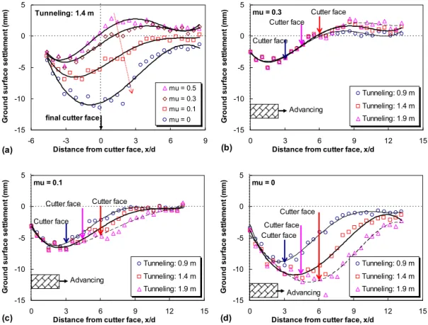
5, 0.3, 0.1 and 0) and keeping other properties identical for soils in this specified zone.Fig. 4. (Color online.) Ground surface settlements: (a) for different soil-conditioning treatments during tunnel advances up to 1.4 m; (b) forμ=0.3 during different tunnel advances up to 0.9, 1.4 and 1.9 m; (c) forμ=0.1 during different tunnel advances up to 0.9, 1.4, and 1.9 m; (d) forμ=0 during different tunnel advances up to 0.9, 1.4, and 1.9 m.
Note that the tail gap and the friction between the tunneling and soil particles depend not only on the soil itself, but also on the lining, which is controlled by its quality and construction technology, etc. [25]. For the sake of simplicity and the focus on the soil conditioning effect, the tail gap was not considered and the interparticle friction between soil particles and walls was handled in the same manner as the soil.
Furthermore, it is known in the Geotechnical Engineering community that the amplified gravity will lead a small-size ground to simulate a large-size one without scale effect. In addition, the tunnel lining and machine are generally made from concrete and steel with their stiffness/modulus significantly larger than that of the surrounding soil. Hence, it can be considered that the DEM modeling represents a real ground size of 40
×
20 m with a tunnel of 3 m diameter, and there is little scale effect in this study. Since the particle assembly can be considered as a real soil based on its mechanical behavior, the simulation follows the real construction procedure, the influence and of soil conditioning can be qualitatively investigated with microstructural insight.3. Influence of soil conditioning on ground deformation
The influence of soil conditioning on the ground deformation during longitudinal tunneling was investigated on different aspects, i.e. ground surface settlement, vertical and horizontal displacements, averaged pure rotation rate of particles, etc. Such complete observation has never been reported in practice due to technological problems in monitoring displacements in situ.
3.1. Ground surface settlement
Four DEM models of the advance of the cutterhead up to 1.4 m were carried out with different inter-particle friction properties (
μ
=
0.
5, 0.3, 0.1 and 0) in the soil conditioning zone. The ground surface settlement for each case was plotted versus the relative distance from the cutter face x/
d (d representing the diameter of tunnel) in Fig. 4(a). All results show that: (1) the more fluid the soils in the conditioning zone, the more surface settlement occurs; (2) conditioned soils improve the upheaval of the ground surface; (3) the distance between the biggest surface settlement and the final cutter face is decreasing with the increase of soil conditioning.It is worth pointing out that in the case without soil conditioning (
μ
=
0.
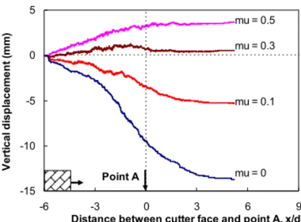
5) the surface settlement above the cutter-head is slight, similar to that obtained from centrifuge modeling without soil conditioning[3]. Surface settlement above theFig. 5. (Color online.) Vertical displacements at observation point A for different soil-conditioning treatments during tunnel advance up to 3.4 m.
Fig. 6. (Color online.) Vertical displacements for different soil-conditioning treatments: (a) at observation point B during tunnel advance up to 3.4 m; (b) at
observation point C during tunnel advance up to 1.8 m.
cutterhead increases with soil conditioning from
μ
=
0.
5 to 0, which is similar to the behavior observed in real construc-tions with soil conditioning[26,27]. Moreover, Attewell and Woodman[26] concluded that the average amplitude of the surface settlement above the cutterhead is about half of maximum settlement based on many field investigations, which corresponds to DEM modeling in this study with theμ
value between 0.1 and 0.3 (seeFig. 4(a)). Such observation and com-parison demonstrate that the research presented in this paper is reasonable, although few data can be found only focused on the soil conditioning effect in a real tunnel.Furthermore, for each specified soil conditioning, DEM simulations were also carried out for different advance distances of the cutterhead up to 0.9 and 1.9 m. The ground surface settlement curves together with that of the advance of 1.4 m were compared to each other for
μ
=
0.
3 inFig. 4(b), forμ
=
0.
1 inFig. 4(c) and forμ
=
0 inFig. 4(d). The comparisons show that, even under the same earth pressure balance tunneling, different conditioned soils have different ground deformation behaviors: (1) for soils a little conditioned (μ
=
0.
3), the tunnel advance changes the subsidence slightly, but increases the upheaval significantly; (2) more conditioned soils (μ
=
0.
1) can erase the upheaval during tunnel advancing and change the maximum subsidence slightly; (3) for soils very conditioned (μ
=
0), the surface settlement deepens and moves forwards with the cutterhead advance. This trend is associated with the improvement of fluidity and the reduction of friction forces for conditioned soils fromμ
=
0.
5 to 0 (seeFigs. 1 and 2). These results are helpful to determine the conditioned soils and explain the ground surface behavior for real constructions.3.2. Vertical displacements
Vertical displacements at observation points A, B and C (seeFig. 3) were obtained from DEM models with the advance of the tunnel up to 3.4 m for different soil-conditioning treatments (
μ
=
0.
5, 0.3, 0.1 and 0). The sign of the vertical displacement is defined positive for upheaval.Fig. 5shows a significant influence of the soil conditioning on the evolution of vertical displacement at point A during the longitudinal advance of the tunnel, i.e. from upheaval with
μ
=
0.
5 to subsidence withμ
=
0. Moreover, the vertical displacement develops rapidly before the cutterhead arrives at A, and then changes slowly to converge with the tunnel advance.The evolution of vertical displacement at point B inFig. 6(a) is similar to that at point A, but with more upheaval. For point C located on the centerline of the tunnel and ahead of the cutterhead (seeFig. 3), during the cutterhead advance up
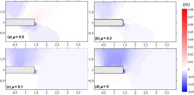
Fig. 7. (Color online.) Field of vertical displacement at the tunnel advance of 1.4 m for different soil-conditioning treatments.
Fig. 8. (Color online.) Horizontal displacements for different soil conditioning: (a) at observation point B during tunnel advance up to 3.4 m; (b) at
observation point C during tunnel advance up to 1.8 m.
to a distance equal to one tunnel diameter before point C , the evolution of the vertical displacement inFig. 6(b) is similar to that at point B, but with a smaller amplitude. For the following advance towards point C , a large subsidence occurs rapidly in all cases. Finally, point C can no longer be used, since the tunnel passed through.
Fig. 7shows the field of vertical displacement for the advance of the tunnel up to 1.4 m with different soil-conditioning treatments. From
μ
=
0.
5 to 0, it can be concluded that: (1) the settlement of soils over the tunneling increases, in con-cordance with Figs. 4–6; (2) the deformation of soils above the cutterhead is from upheaval to subsidence, in concordance withFigs. 4–6; (3) the biggest subsidence occurs in the area close to the cutter face, in concordance withFig. 6b; (4) the settlement of the soils under the cutterhead decreases.Above all, a suitable soil conditioning between
μ
=
0.
3 and 0.1 can reduce the vertical ground displacement during longitudinal tunneling.3.3. Horizontal displacements
Horizontal displacements at observation points B and C were obtained from DEM models with the advance of tunnel up to 3.4 m and different soil-conditioning treatments. The sign of horizontal displacement is defined positive following the direction of the tunnel advance.
Fig. 8(a) shows a significant influence of the soil conditioning on the evolution of horizontal displacement at point B during the longitudinal tunneling, i.e. from positive with
μ
=
0.
5 to negative withμ
=
0. The horizontal displacement develops rapidly before the cutterhead approaches B, and then becomes almost stable with the advance of the tunnel. For point C , during the cutterhead advance up to one tunnel diameter distance before point C , the evolution of horizontal displacement in Fig. 8(b) is similar to that at point B. For the following advancing towards point C , a large horizontal displacement occurs rapidly in all cases. Finally, point C can no longer be used since the tunnel passed through.Fig. 9. (Color online.) Field of horizontal displacement at the tunnel advance of 1.4 m for different soil-conditioning treatments.
Fig. 10. Force chains in the soil around the cutter face of the tunnel for different soil-conditioning treatments.
Fig. 9shows the field of horizontal displacement for the advance of tunnel up to 1.4 m with different soil-conditioning treatments. The biggest horizontal displacement occurs at the center point of the cutter face, and the displacement becomes slightly with the increasing distance from this point. From
μ
=
0.
5 to 0, the influence area due to the tunneling on the horizontal displacement of soils becomes smaller. Note that the blue color in all figures is due to a small negative value which is close to zero, similar to white area due to a small positive value and close to zero.Above all, soil conditioning can generally reduce the horizontal displacement of ground during longitudinal tunneling.
3.4. Interparticle force chain
Since the geometry is the same for all tunnel models, the interparticle forces are comparable for different cases to demonstrate the soil conditioning effect from the point of view of the microstructure. Fig. 10presents the contact forces between particles for the selected zone around the cutterhead of tunnel with different soil-conditioning treatments. The width of the lines in the figure represents the magnitude of the contact force between particles, and the direction of the lines represents the direction of the contact force. From Fig. 10(a) to 10(d), the contact forces above and in front of the cutter face of the tunnel generally decrease with increasing soil conditioning. This evolution can be revealed to the resulting soil conditioning effect on the ground deformation during longitudinal tunneling.
4. Conclusions
The EPB shield tunneling with a buried depth of three times the tunnel diameter was modeled with excavating and supporting simultaneously. A soil conditioning zone was specified including the soil chamber and a cap-shaped area in front of the cutterhead. Different cases of soil conditioning were modeled by reducing the interparticle friction of soils in this specified zone.
The influence of soil conditioning on the ground deformation during longitudinal tunneling was investigated on different aspects, i.e. ground surface settlement, vertical and horizontal displacements, averaged pure rotation rate of particles:
•
for ground surface settlement, (1) more conditioned the soils in the conditioning zone are, more surface settlement occurs; (2) well controlled conditioned soils can erase the upheaval of the ground surface, but highly conditioned soils will cause the surface settlement deepening and moving forwards with the cutterhead advancing; (3) the distance between the biggest surface settlement and the final cutter face is decreasing with the increase of soil conditioning.•
For a vertical displacement, (1) more conditioned soils increase the settlement of soils over the tunneling; (2) the deformation of soils above the cutterhead goes from upheaval to subsidence with the increase of soil conditioning; (3) the biggest subsidence occurs in the area close to the cutter face; (4) the settlement of soils under the cutterhead decreases with the increase of soil conditioning.•
For a horizontal displacement, (1) the biggest horizontal displacement occurs at the center point of cutter face, and the displacement becomes smaller with the increasing distance from this point; (2) the influence area due to the tunneling on the horizontal displacement of soils becomes smaller with the increase of soil conditioning.The trend of ground deformation is associated with the fluidity from poor to favorite and the mechanical properties from dilative to contractive for conditioned soils from
μ
=
0.
5 to 0. Such phenomena are also related to the inter-particle forces from the point of view of the microstructure. These results are helpful to determine the conditioned soils and control the ground deformation for real constructions.Future works on underground engineering construction will be carried out numerically on soils with different internal friction angles by using the rolling resistance model[14], the bonded granular material[16], and unsaturated soils[13]with more realistic dimensions with the rapid development of computer technology. Furthermore, other methods (e.g., coupled FEM/DEM and 3D DEM) can be used as alternative approaches to solve this class of problems.
Acknowledgements
This research was financially supported by the China National Funds for Distinguished Young Scientists (Grant No. 51025932), the National Natural Science Foundation of China (Grant Nos. 10972158, 41240024, 41372285). These sup-ports are greatly appreciated. In addition, the authors thank the first author’s former MSc student, Mr. Fuzhou Wang, for his carrying out DEM simulations.
References
[1]D. Peila, C. Oggeri, L. Borio, Using the slump test to assess the behavior of conditioned soil for EPB tunneling, Environ. Eng. Geosci. 15 (3) (2009) 167–174.
[2]M.D. Bolton, Y.C. Lu, J.S. Sharma, Centrifuge models of tunnel construction and compensation grouting, in: R.J. Mair, R.N. Taylor (Eds.), Proc. Int. Symp. on Geotechnical Aspects of Underground Construction in Soft Ground, Balkema, Rotterdam, The Netherlands, 1996, pp. 471–476.
[3]T. Nomoto, S. Imamura, T. Hagiwara, O. Kusakabe, N. Fujii, Shield tunnel construction in centrifuge, J. Geotech. Geoenviron. Eng. 125 (4) (1999) 289–300. [4]M.A. Meguid, O. Saada, M.A. Nunes, J. Mattar, Physical modeling of tunnels in soft ground: A review, Tunn. Undergr. Space Technol. 23 (2) (2008)
185–198.
[5]S. Shibayama, J. Izawa, A. Takahashi, J. Takemura, Q. Kusakabe, Observed behaviour of a tunnel in sand subjected to shear deformation in a centrifuge, Soil Found. 50 (2) (2010) 281–294.
[6]Q. Xu, H. Zhu, W. Ding, X. Ge, Laboratory model tests and field investigations of EPB shield machine tunnelling in soft ground in Shanghai, Tunn. Undergr. Space Technol. 26 (1) (2011) 1–14.
[7]K.S. Wong, C.W.W. Ng, Y.M. Chen, X.C. Bian, Centrifuge and numerical investigation of passive failure of tunnel face in sand, Tunn. Undergr. Space Technol. 28 (2012) 297–303.
[8]M.J. Melis Maynar, L.E. Medina Rodriguez, Discrete numerical model for analysis of earth pressure balance tunnel excavation, J. Geotech. Geoenviron. Eng. 131 (10) (2005) 1234–1242.
[9]S.S. Vardakos, M.S. Gutierrez, N.R. Barton, Back-analysis of Shimizu Tunnel No. 3 by distinct element modeling, Tunn. Undergr. Space Technol. 22 (4) (2007) 401–413.
[10]R.P. Chen, L.J. Tang, D.S. Ling, Y.M. Chen, Face stability analysis of shallow shield tunnels in dry sandy ground using the discrete element method, Comput. Geotech. 38 (2) (2011) 187–195.
[11]P.A. Cundall, O.D.L. Strack, The distinct numerical model for granular assemblies, Geotechnique 29 (1) (1979) 47–65.
[12]M.J. Jiang, J.M. Konrad, S. Leroueil, An efficient technique for generating homogeneous specimens for DEM studies, Comput. Geotech. 30 (7) (2003) 579–597.
[13]M.J. Jiang, S. Leroueil, J.M. Konrad, Insight into strength functions in unsaturated granulate by DEM analysis, Comput. Geotech. 31 (6) (2004) 473–489. [14]M.J. Jiang, H.-S. Yu, D. Harris, A novel discrete model for granular material incorporating rolling resistance, Comput. Geotech. 32 (5) (2005) 340–357. [15]M.J. Jiang, H.-S. Yu, D. Harris, Discrete element modelling of deep penetration in granular soils, Int. J. Numer. Anal. Methods Geomech. 30 (4) (2006)
335–361.
[16]M.J. Jiang, H.-S. Yu, S. Leroueil, A simple and efficient approach to capturing bonding effect in naturally micro-structured sands by discrete element method, Int. J. Numer. Anal. Methods Geomech. 69 (2007) 1158–1193.
[17]M.J. Jiang, H.H. Zhu, D. Harris, Classical and non-classical kinematic fields of two-dimensional penetration tests on granular ground by discrete element method analyses, Granul. Matter 10 (2008) 439–455.
[18]M.J. Jiang, S. Leroueil, H.H. Zhu, H.-S. Yu, J.M. Konrad, Two-dimensional discrete element theory for rough particles, Int. J. Geomech. 9 (1) (2009) 20–33. [19]M.J. Jiang, H.B. Yan, H.H. Zhu, D. Utili, Modeling shear behavior and strain localization in cemented sands by two-dimensional distinct element method
analyses, Comput. Geotech. 38 (2011) 14–29.
[21]Z.-Y. Yin, C.S. Chang, P.-Y. Hicher, M. Karstunen, Micromechanical analysis of kinematic hardening in natural clay, Int. J. Plast. 25 (8) (2009) 1413–1435. [22]Z.-Y. Yin, C.S. Chang, P.-Y. Hicher, Micromechanical modelling for effect of inherent anisotropy on cyclic behaviour of sand, Int. J. Solids Struct.
47 (14–15) (2010) 1933–1951.
[23]Z.-Y. Yin, M. Hattab, P.-Y. Hicherm, Multiscale modeling of a sensitive marine clay, Int. J. Numer. Anal. Methods Geomech. 35 (15) (2011) 1682–1702. [24]Z.-Y. Yin, C.S. Chang, Stress-dilatancy for sand under loading and unloading conditions, Int. J. Numer. Anal. Methods Geomech. 37 (8) (2013) 855–870. [25]M.J. Jiang, Z.-Y. Yin, Analysis of stress redistribution in soil and earth pressure on tunnel lining by discrete element method, Tunn. Undergr. Space
Technol. 32 (2012) 251–259.
[26]P.B. Attewell, J.P. Woodman, Predicting the dynamics of ground settlement and its derivatives caused by tunnelling in soil, Ground Eng. Lond. 15 (8) (1982) 13–22.
[27]D.I. Harris, R.J. Mair, J.P. Love, R.N. Taylor, T.O. Henderson, Observations of ground and structure movements for compensation grouting during tunnel construction at Waterloo station, Geotechnique 44 (4) (1994) 691–713.